What happened?
The printer displays the message "Failed to home the X-axis. Make sure there is no obstacle on the X-axis".
Error name: Homing error X
Error code: #31304 (CORE One) #35304 (CORE One L) #36304 (CORE One INDX) #17304 (XL)
The error is most likely caused by a bad movement of the print head along the X-axis.
How to fix it?
Make sure the X-axis can move correctly
Make sure there are no obstructions in the path of the X-axis. For example, there might be a piece of filament stuck around the belt or on a linear rail from a previous print.
Check the belt tension
A loose or overtightened belt can cause inconsistent movement that can trigger the error. Check the belt tension, following the dedicated guide for your printer model.
Check your X/Y axis motors and pulleys
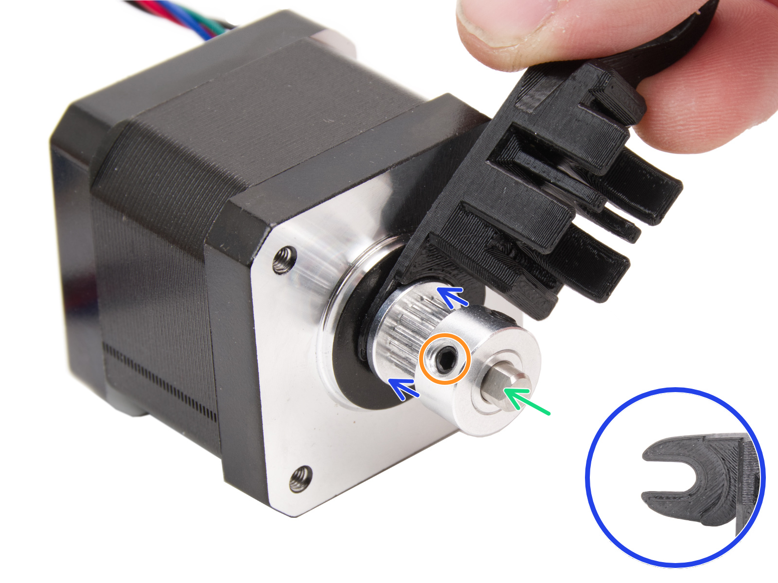
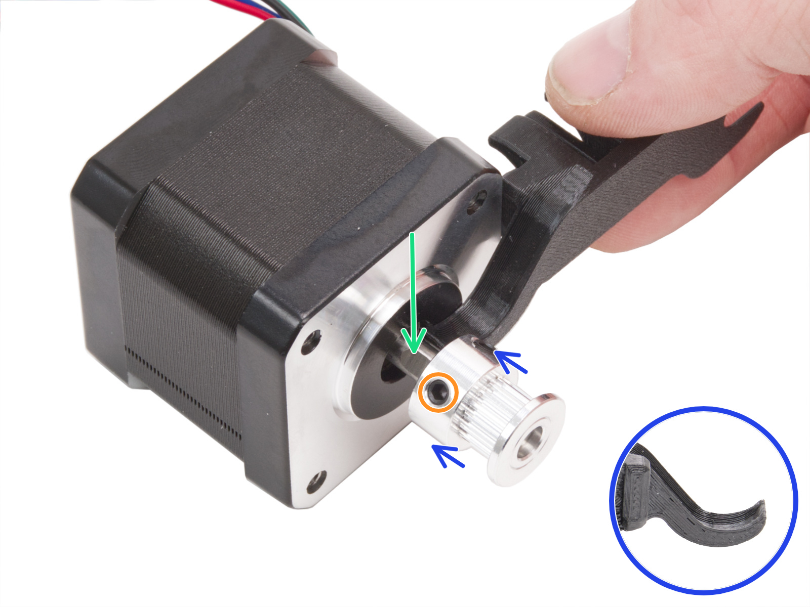
If one of the motor pulleys loosens over time, it will misalign and contribute to inconsistent movement. The pulleys are positioned differently on each of the two XY motors. Each motor pulley has two set screws, one of which has to be aligned with the flat part of the motor shaft.
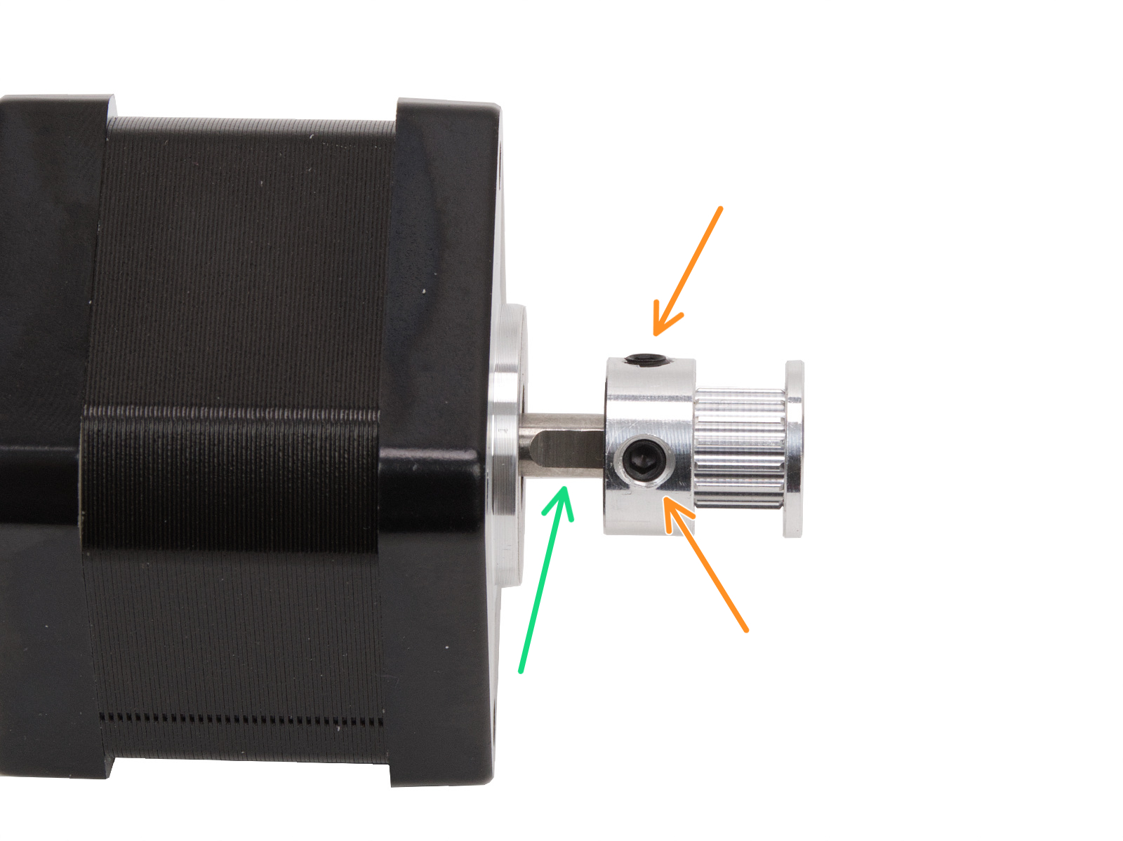
Note that the pulley position and orientation can vary across printers and their motors.
CORE One, CORE One L
The pulleys are positioned differently on each of the two X and Y motors. Looking from the front of the printer:
- Left
- The teeth for the belt are above the set screws.
- Right
- The teeth for the belt are below the set screws.
 |  |
XL
The pulleys are positioned differently on each of the two XY motors. Looking from the front of the printer:
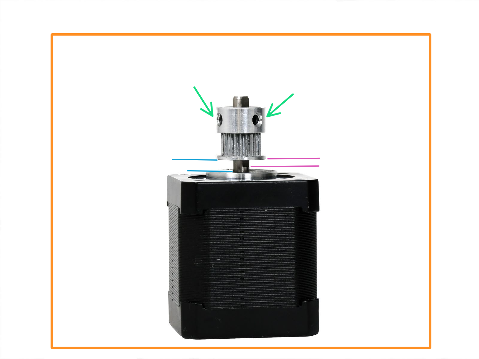
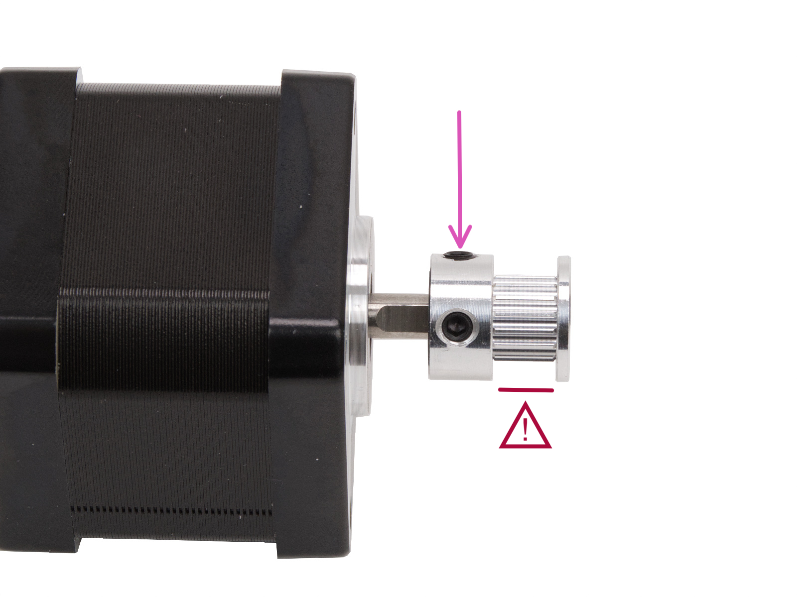
- Left
- Note the orientation of the pulley. The teeth for the belt are below the set screws.
- The pulley is 2.5mm higher than the start of the flat part of the motor shaft. Use the 2.5mm Allen key for reference.
- Alternatively, measure the distance between the beginning of the motor shaft and the pulley, 3.6mm.
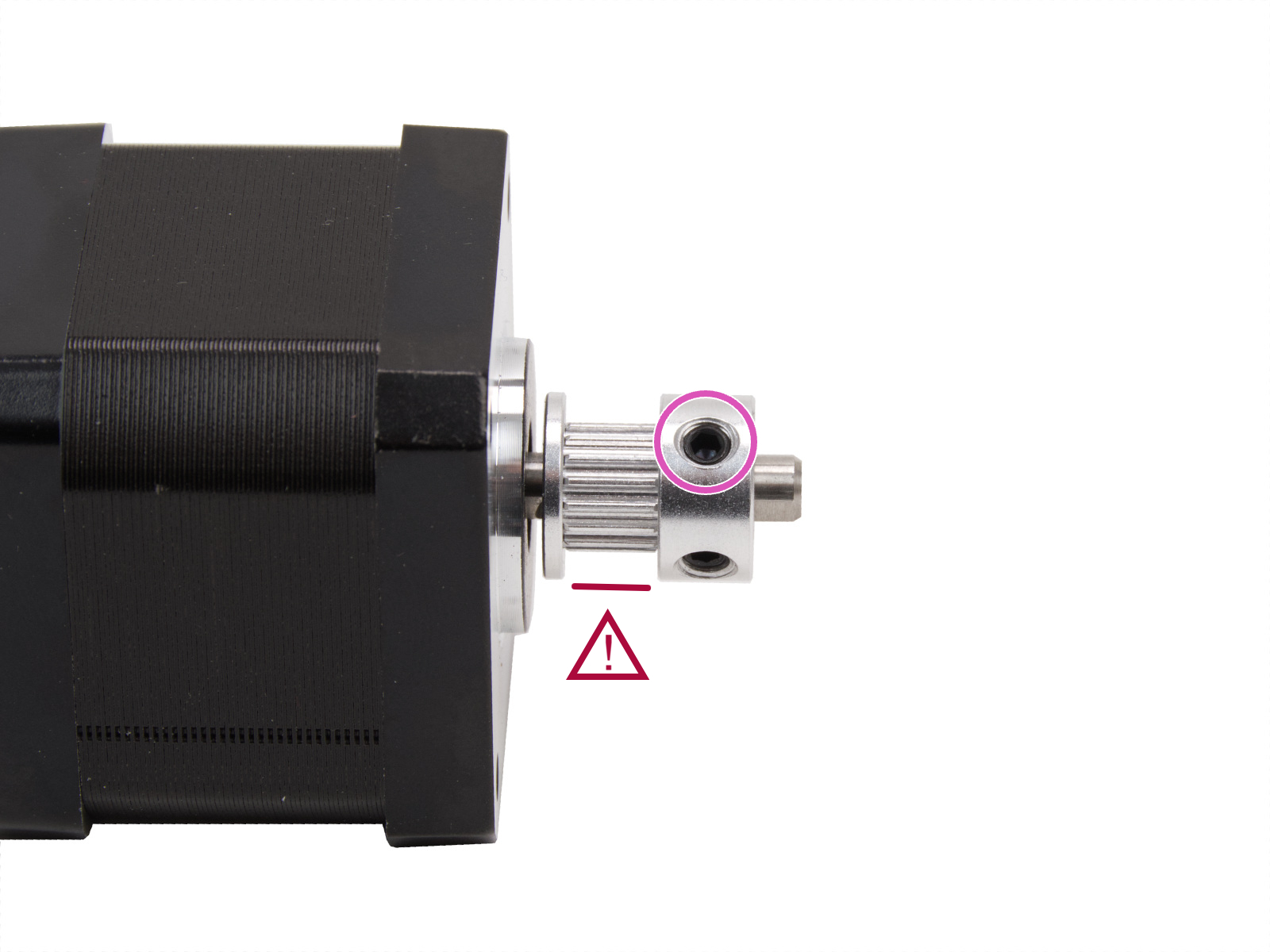
- Right
- Note the orientation of the pulley. The teeth for the belt are above the set screws.
- The pulley is flush with the top edge of the motor shaft.
 |  |
CORE One - How to access XY motors
To access the pulley attached to one of the XY motors, follow the steps below:
- Remove the side panel on the needed side.
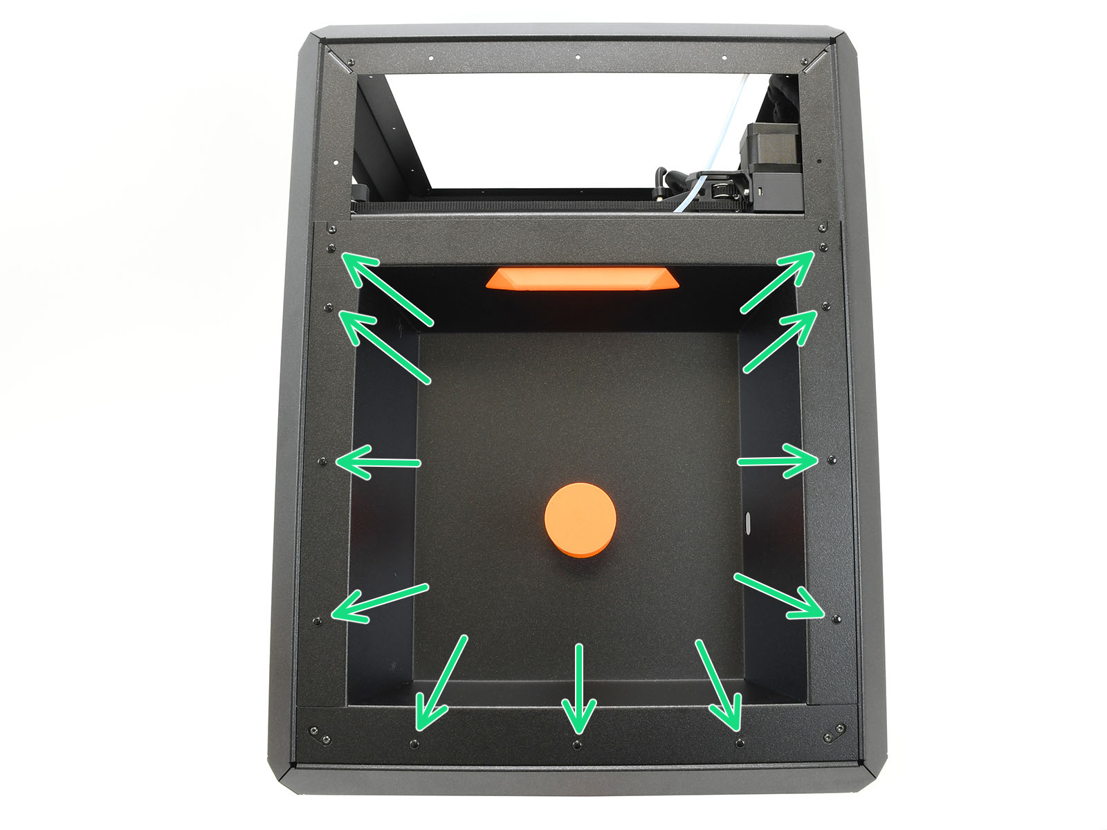
- Left side: remove 11 rivets to release the panel.
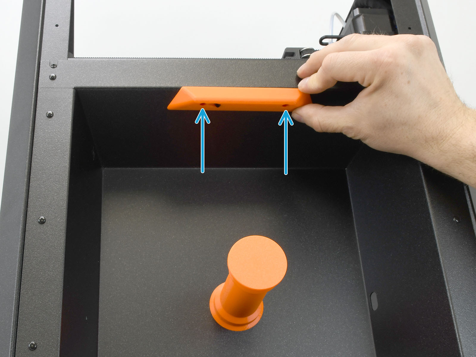
- Right side: release the filament sensor by removing two screws from the handle, then remove 11 rivets to release the panel.
- Slightly loosen the belt tension, by slightly loosening by the same amount the two belt tensioner screws.
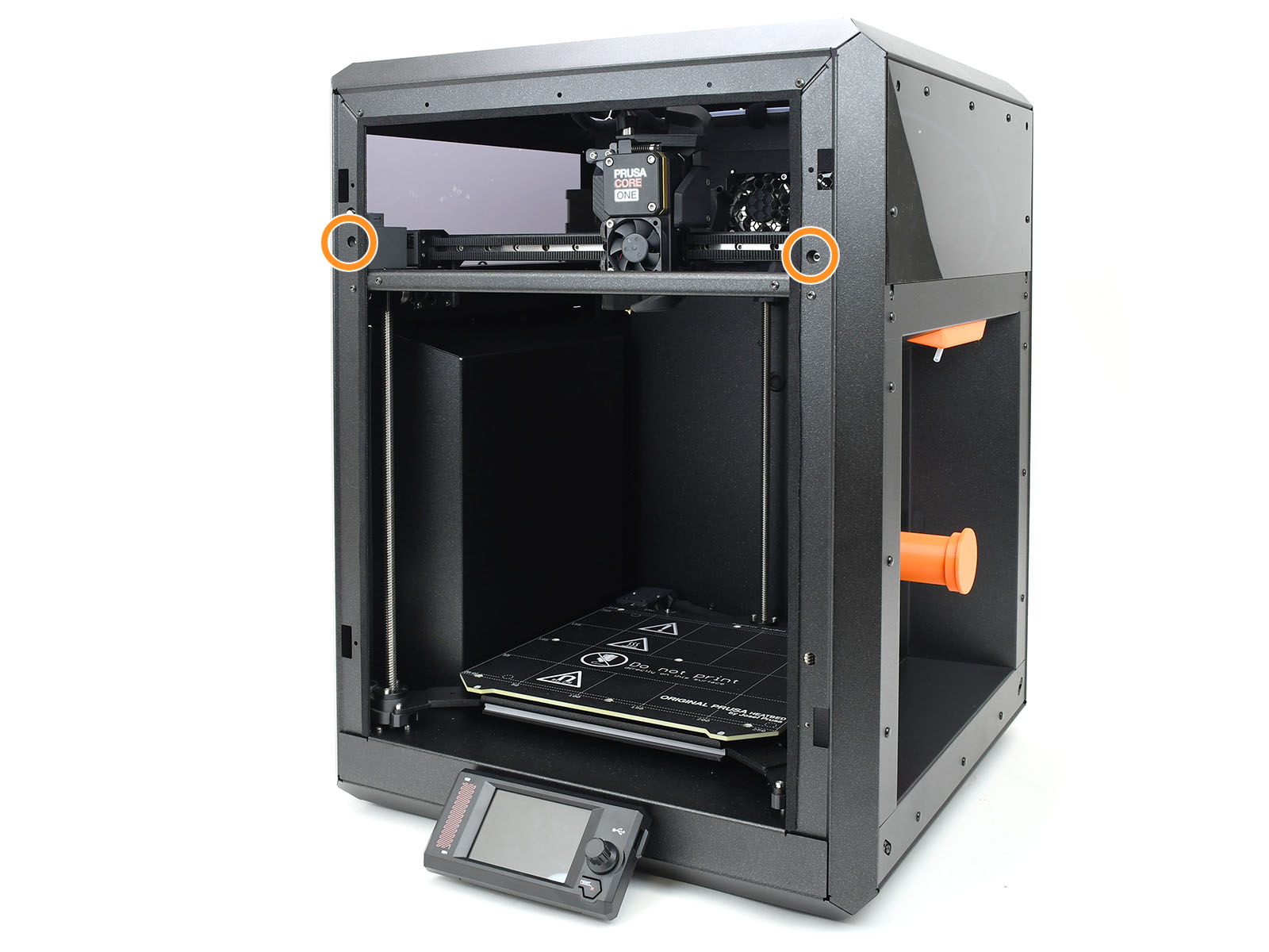
- Remove the four M3x35 screws securing the motor.
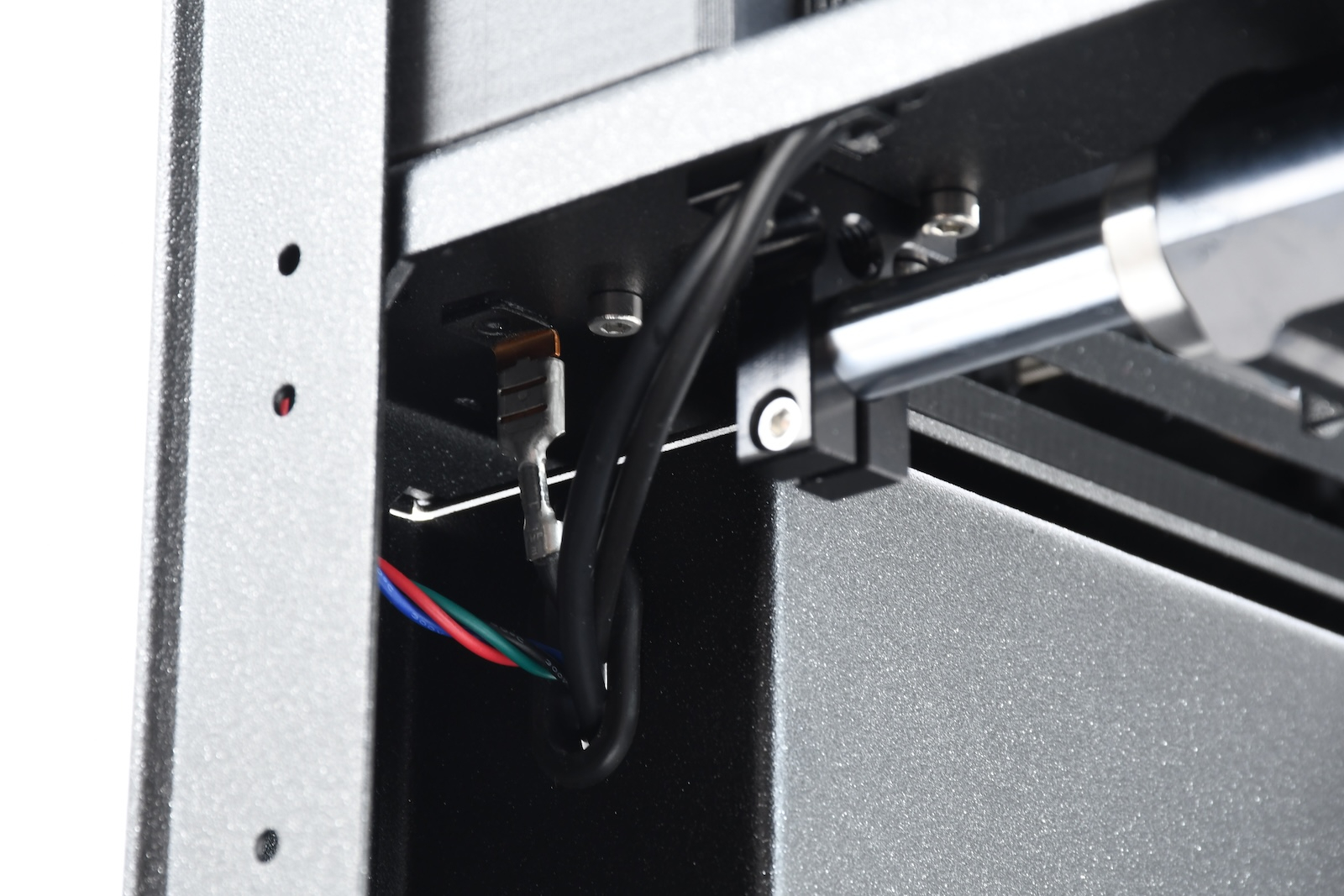
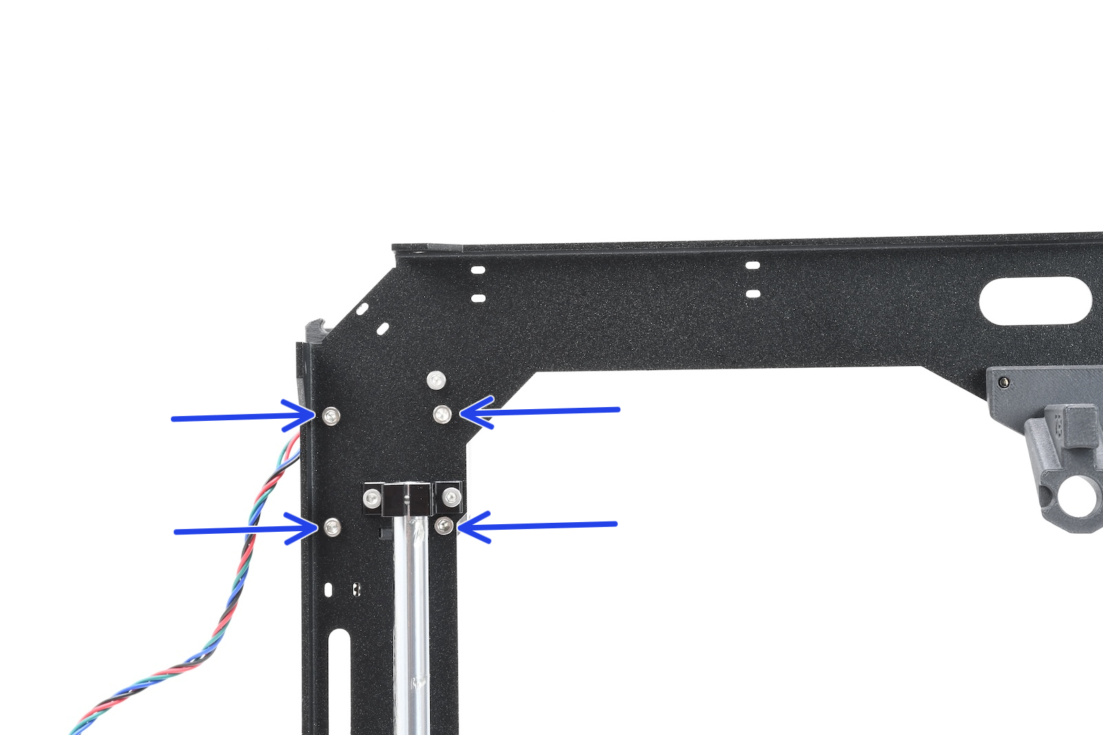
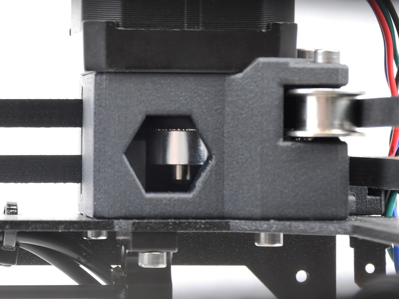
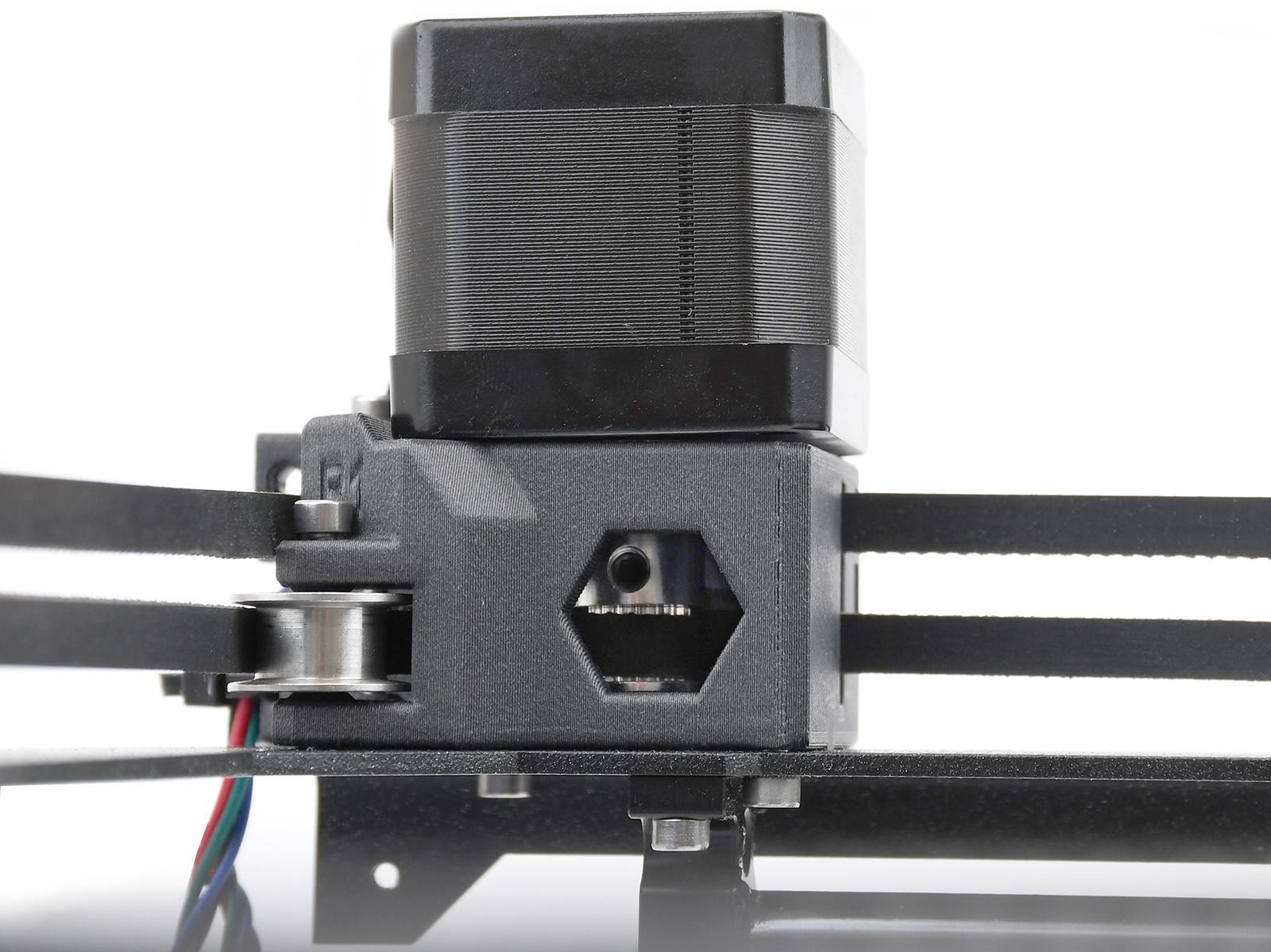
Corner view Bottom view - Slightly raise the motor to make the pulley visible. Note the different distance between pulley and motor on each motor, and that one of the pulley set screws is aligned with the flat part of the motor shaft.
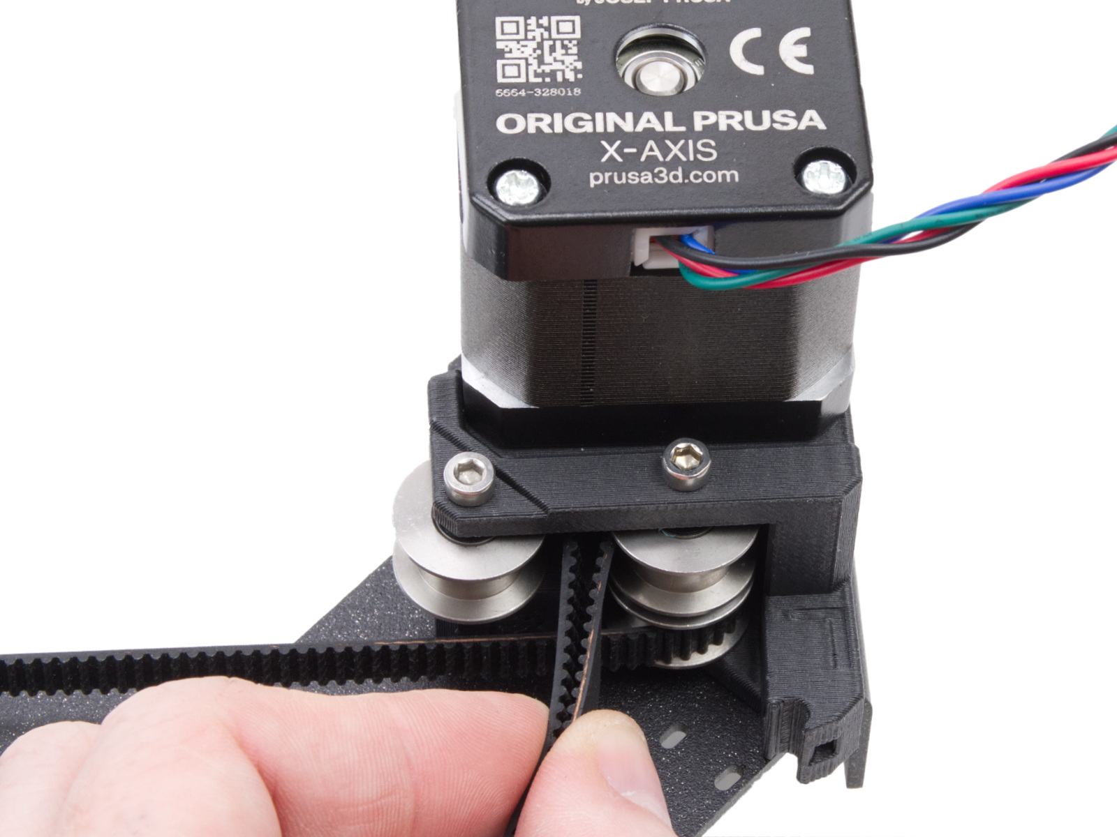
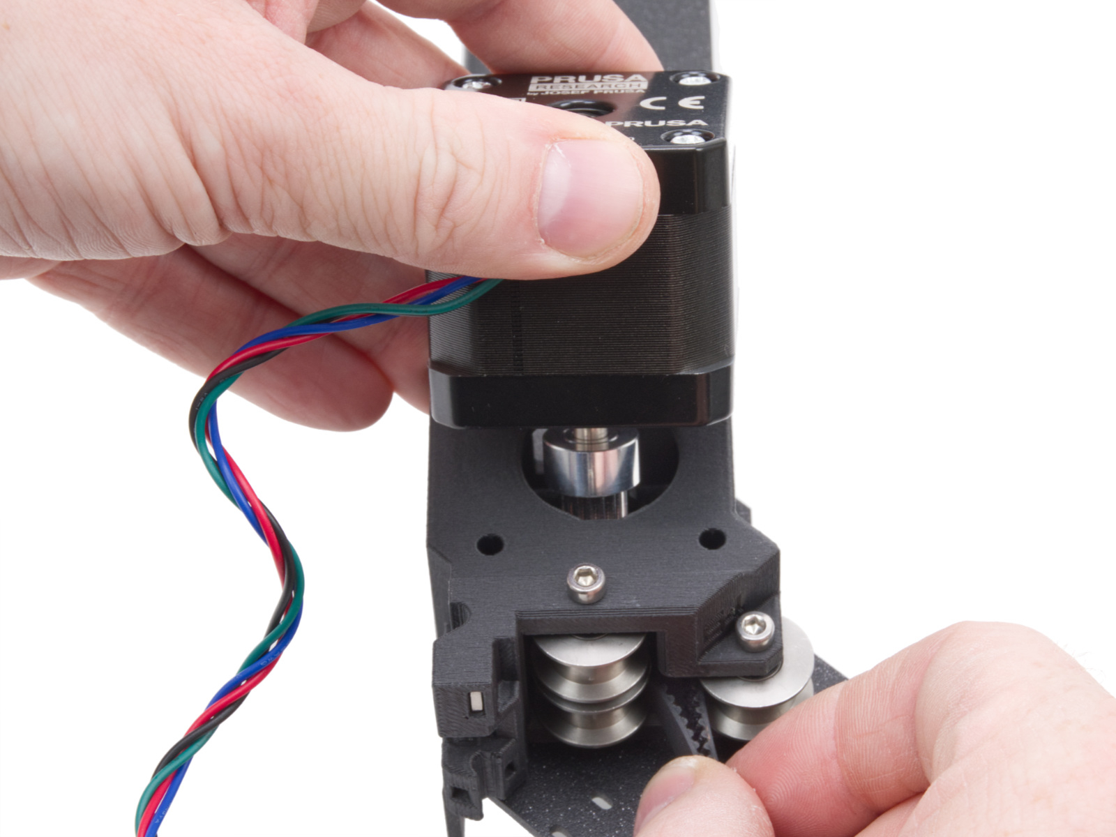
X-motor (left from the front of the printer) Y-motor (right from the front of the printer)