Relevant for


The printer is showing the message: "Overcurrent detected on nozzle heater."
Error name: Nozzle Heater Overcurrent
Error code: #31308 (CORE One) #35308 (CORE One L) #36308 (CORE One INDX) #26308 (MK4S) #13308 (MK4) #27308 (MK3.9S) #21308 (MK3.9)
The error is shown when a damaged wire is on the hotend heater or any of its connections.
The most likely cause of this issue is damage to the hotend heater cable.
On printers equipped with INDX upgrade, try parking the current nozzle, and pick up another nozzle. See if the issue follows the print head to another nozzle, or if the error is only on one nozzle.
If the issue follows the print head, contact our Customer support.
If the issue is only in one nozzle, check the measuring pad to make sure it is clean and has no debris covering it.
On printers equipped with LoveBoard, check the path between the hotend heater and the LoveBoard, and see if any parts are broken or pinched.
If there is no damage, check the cable connection to the LoveBoard board. Try reconnecting the cable to its connector.
In rare cases, this error message can be shown in case of damage to the LoveBoard, the xBuddy board, or the main cable between the two boards. If the cables and connectors are intact, check the boards for any visible damage.
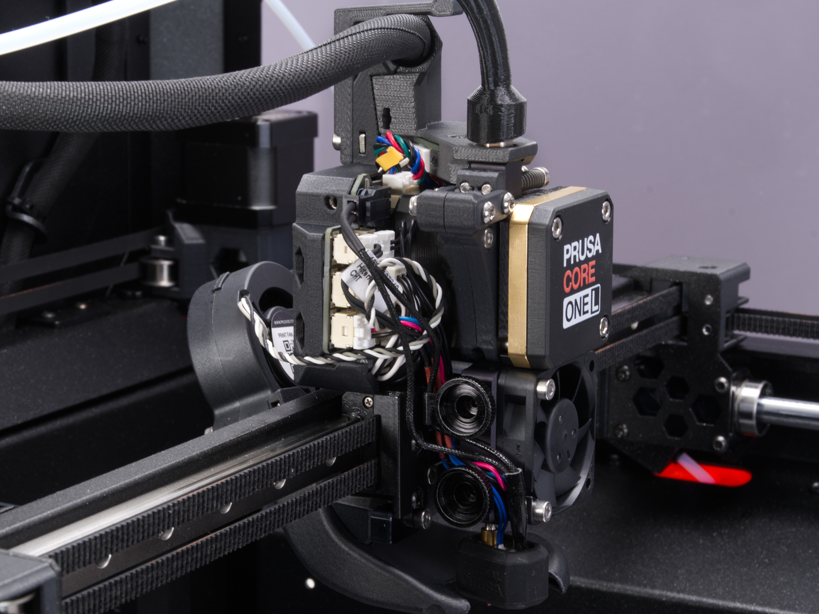
Using a T10 Torx key, loosen and remove one M3x6rT bolt. Then, release the side cover.
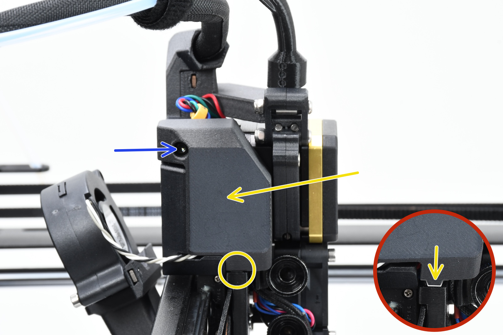 | 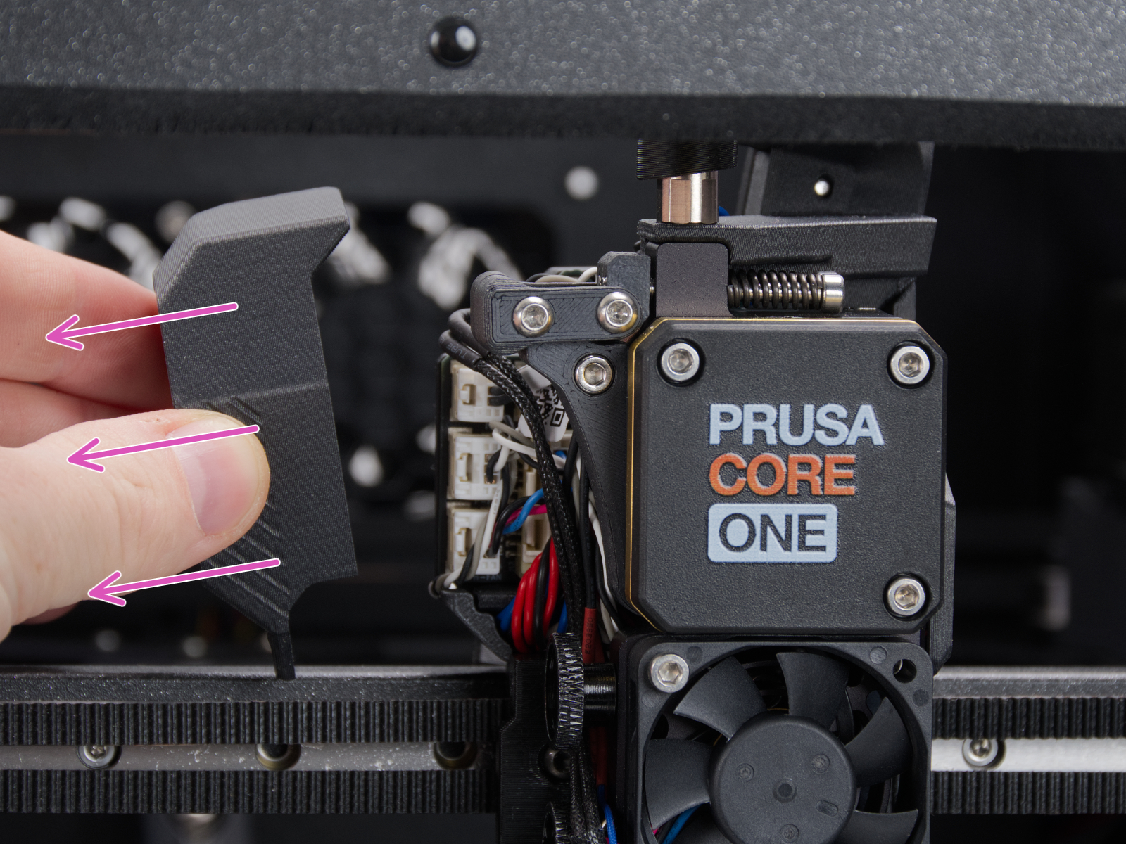 |
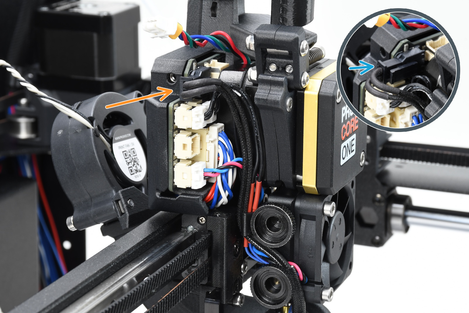
Using a 2.5mm Allen key, remove the M3x10 screw on top of the cover to release it.
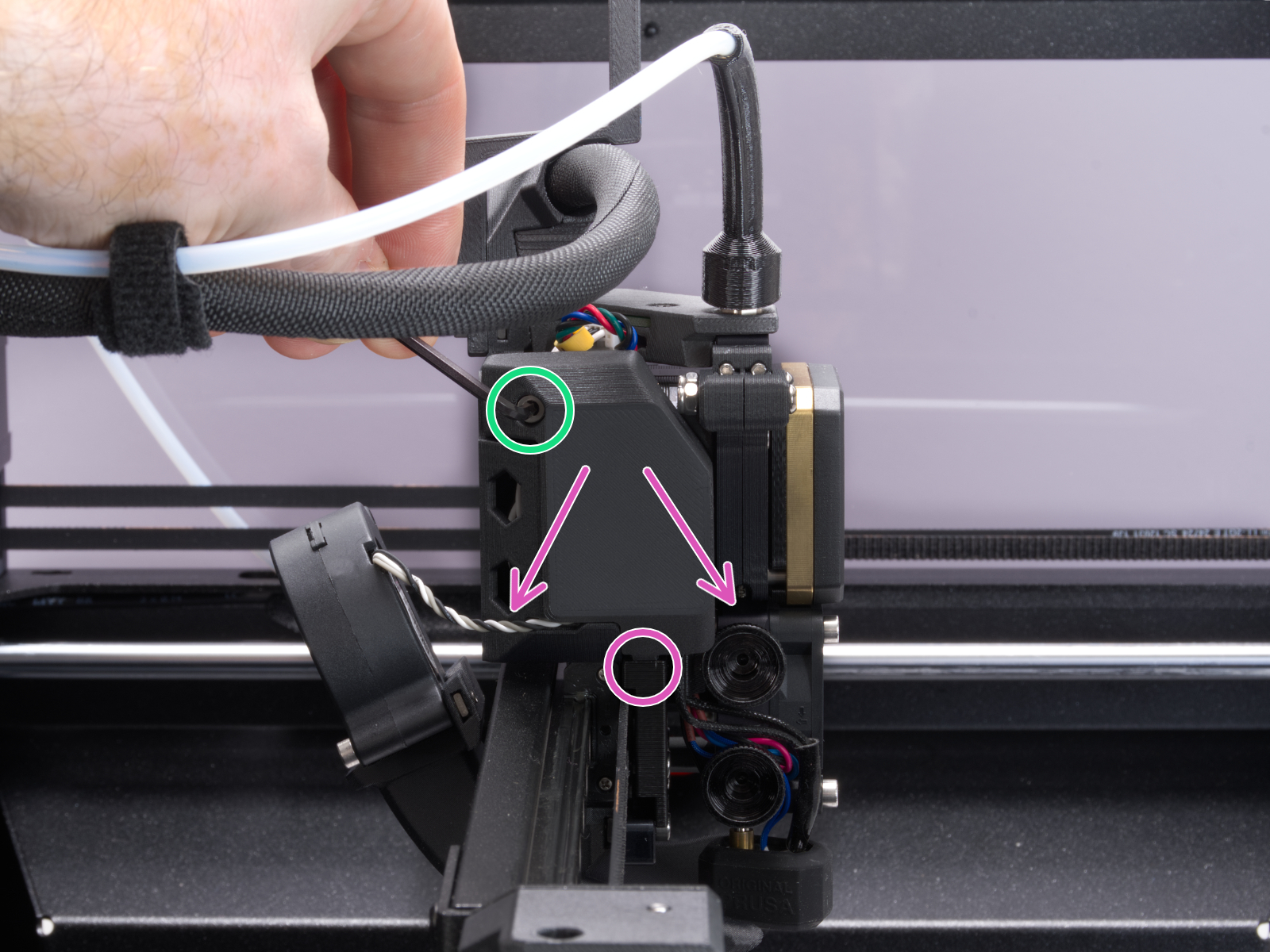 |  |
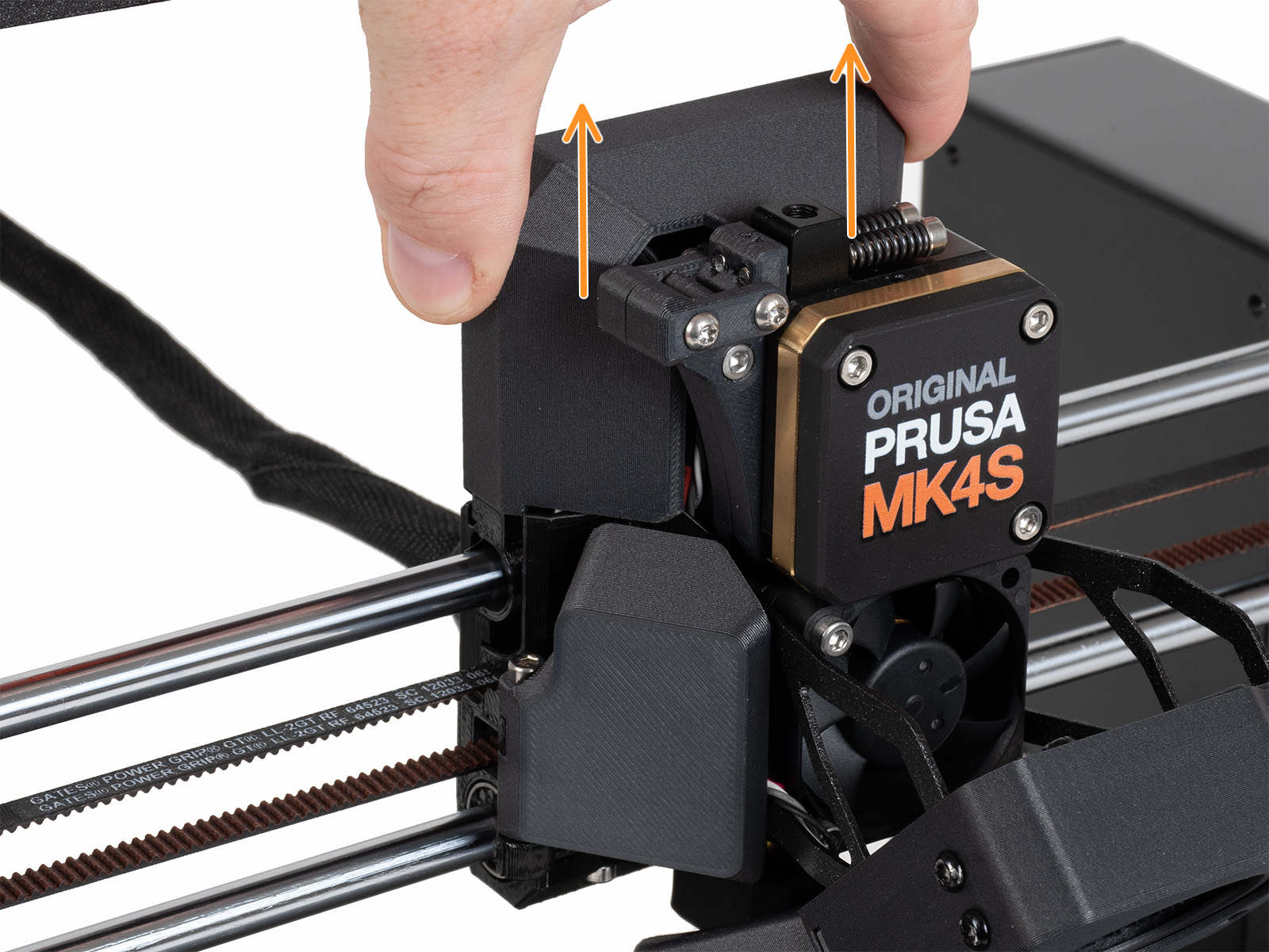
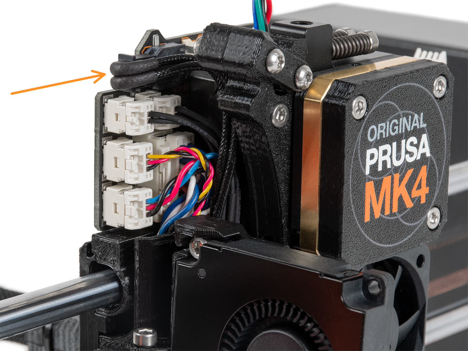
Slide the LoveBoard cover upward to remove it from the Nextruder
 |  |
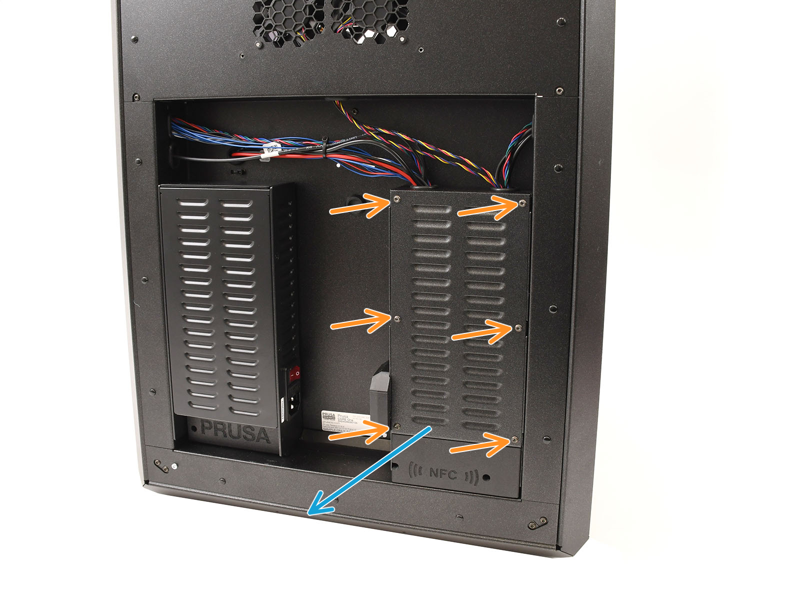
Locate the xBuddy board case. Looking at the printer from its rear, it is the rightmost case.
Using a T10 Torx key, remove six M3x4bT bolts to release the xBuddy box cover.
The bottom larger board is the xBuddy board, while the top smaller board is the xBuddy extension board.
Once accessed:
 | 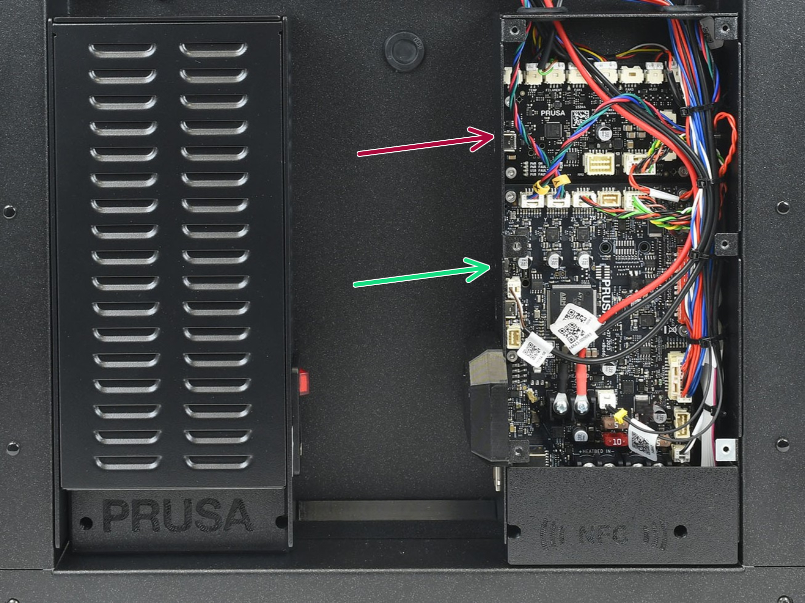 |
| Cover removal - CORE One, CORE One INDX | CORE One without INDX |
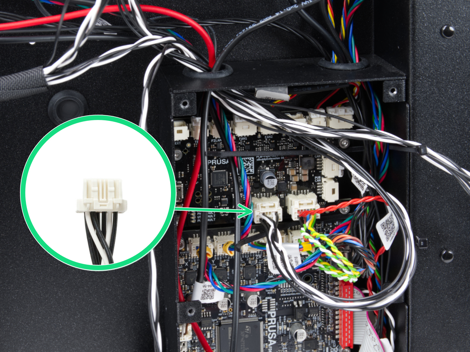 | 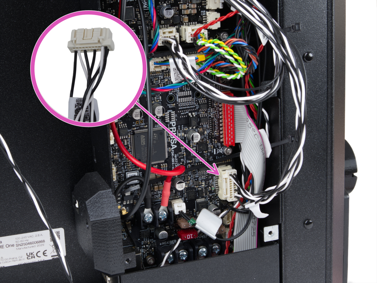 |
| CORE One INDX - head cable Narrow connector, plugged into the MMU-labeled slot on the xBuddy Extension board. | CORE One INDX - head cable Wide connector, plugged it into the Nextruder-labeled slot on the xBuddy board. |
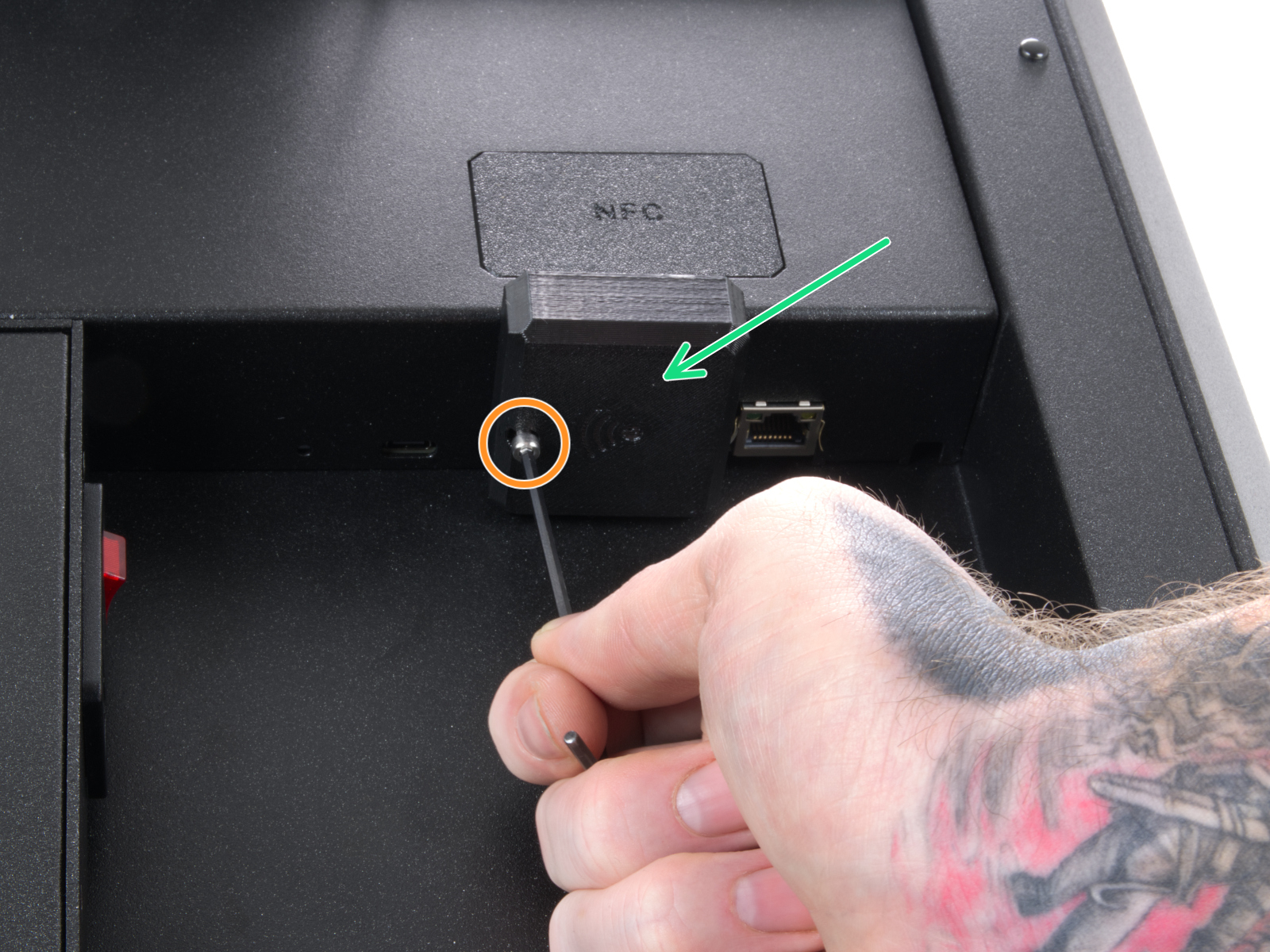
Locate the Wi-Fi module on the rear panel of the printer. Using a 2.5 mm Allen key, remove the M3x14 screw. Gently pull the Wi-Fi module straight downward to remove it from the printer.
 | 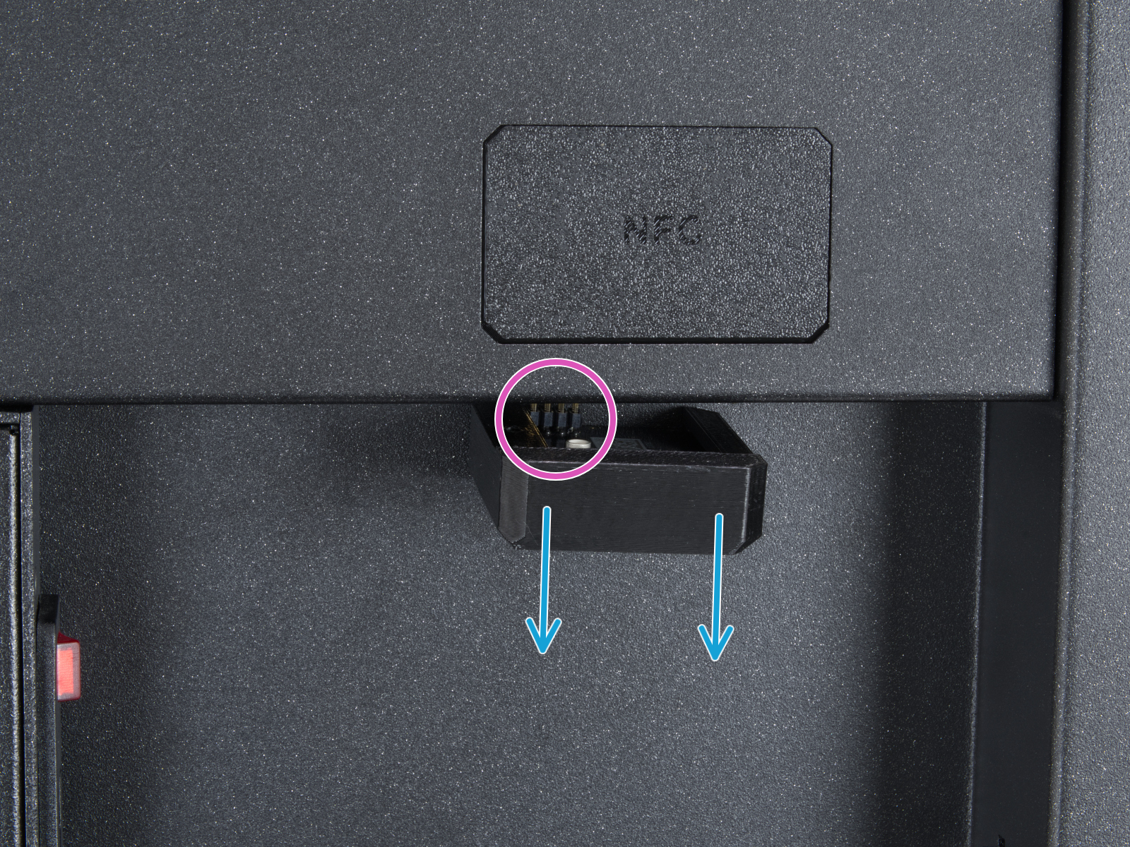 |
From the inside of the printer, locate on the rear side the highlighted M3x4bT bolts.
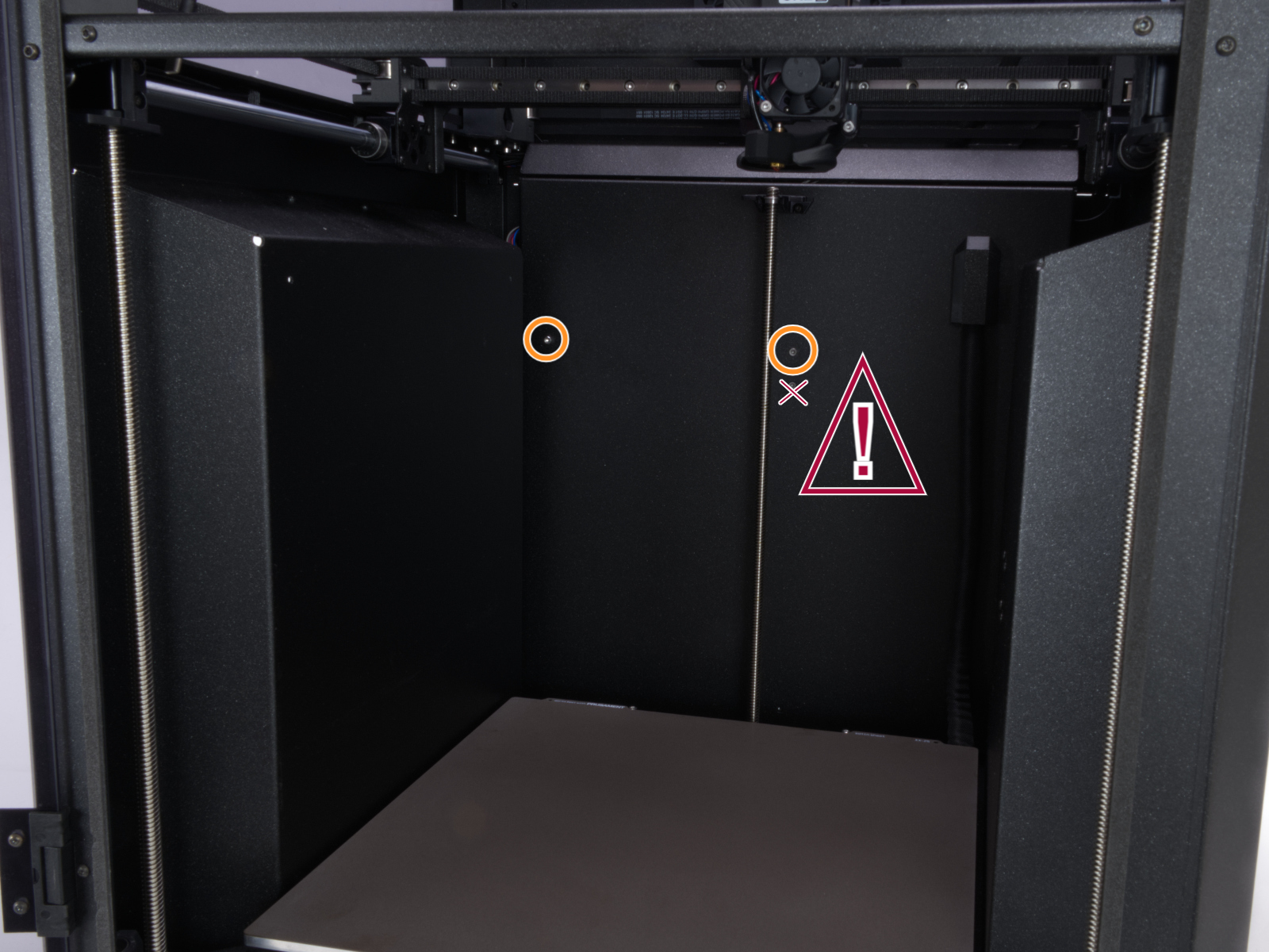
Using a T10 Torx key, remove two M3x4rT bolts to release the rear xBuddy box cover. Lift the cover to expose the xBuddy and xBuddy extension boards.
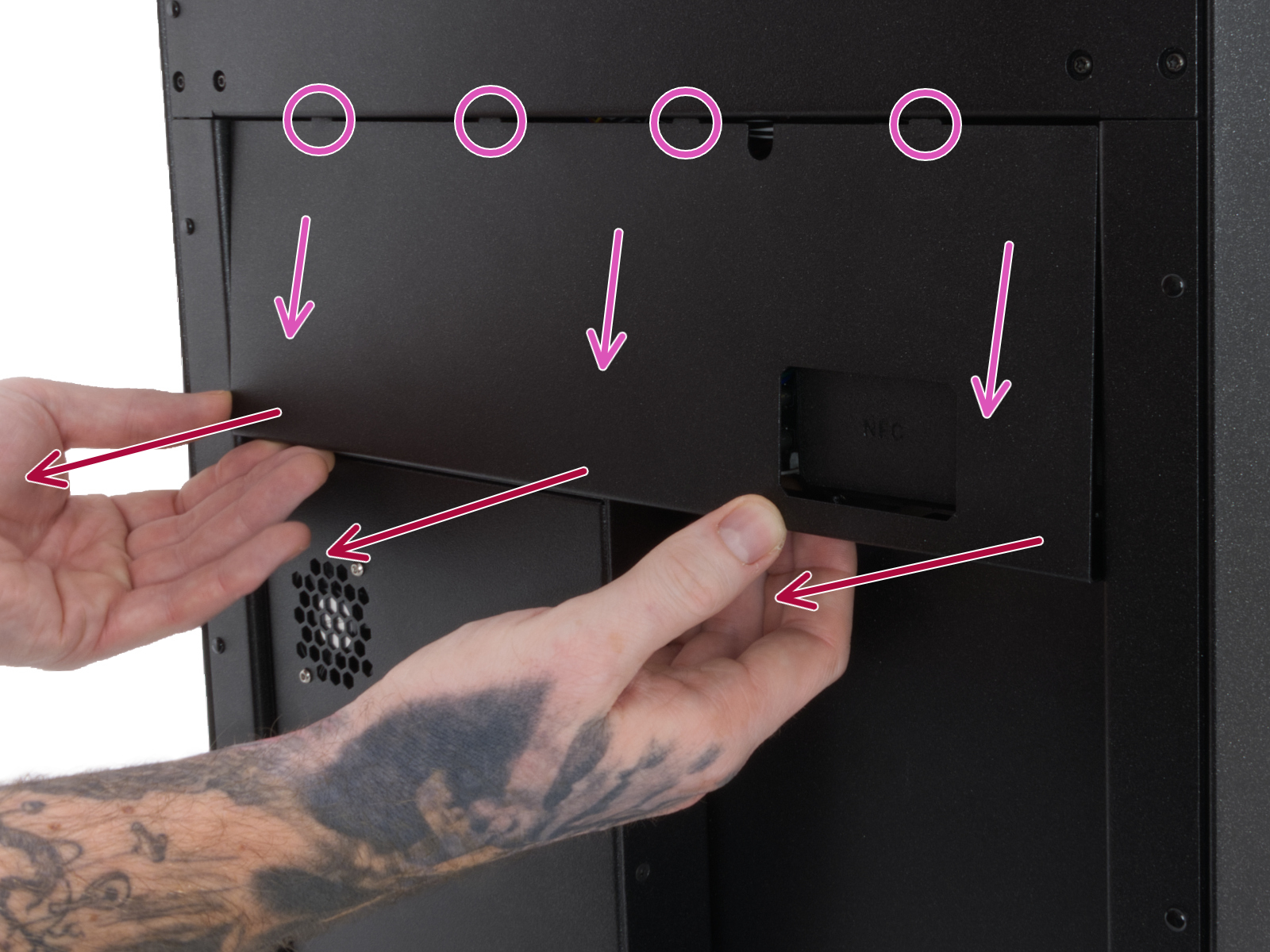 | 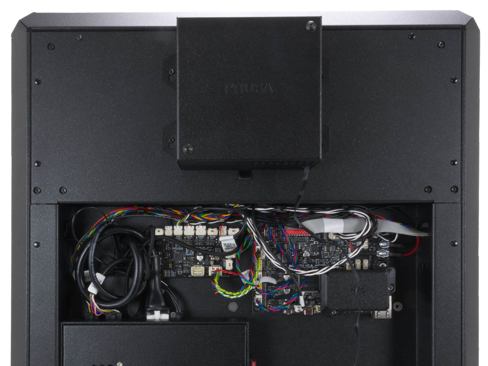 |
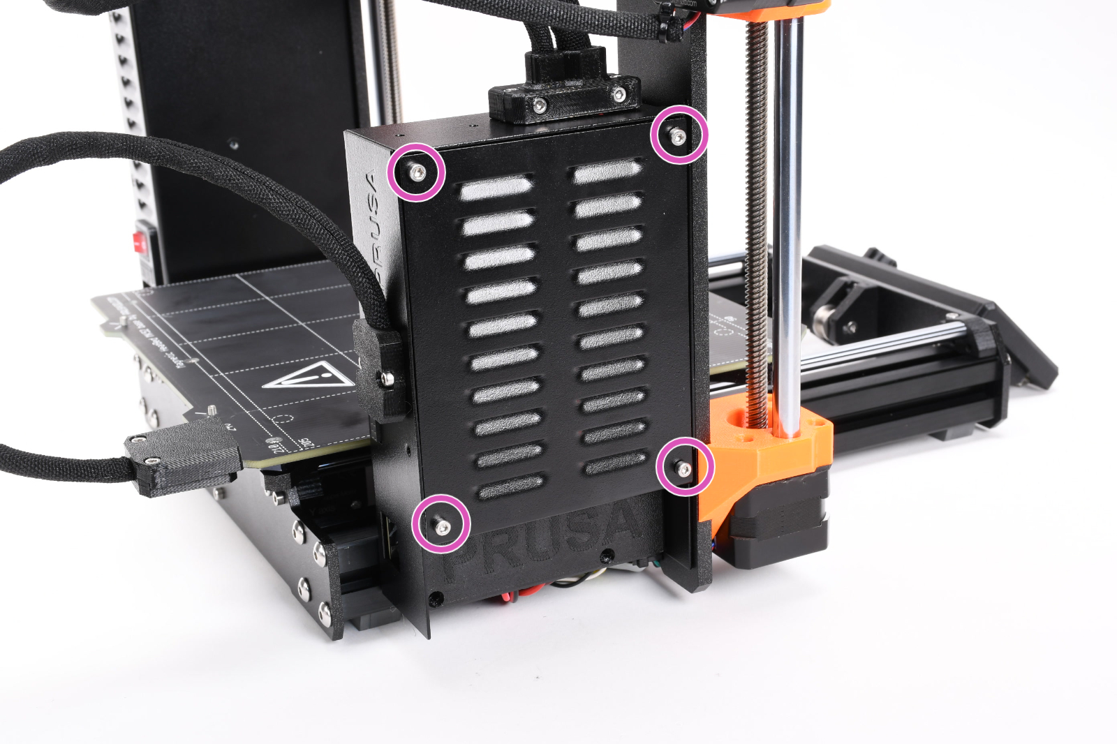
Access the xBuddy board by loosening four M3x6 bolts.
5 comments
Printer was 3 h 17 m into a Gnome supportless with glasses at failure. First print of the Gnome worked well (well, after two failed attempts due to a filament issue)
So I measured the resistance of both:
Working one: 16 Ohm
Defect one: 1 Ohm
Seems to me, that I need a new one :-(