What happened?
The printer is showing the message "Reading ESP firmware failed."
Error name: ESP Error
Error code: #31504 (CORE One) #35504 (CORE One L) #26504 (MK4S) #13504 (MK4) #27504 (MK3.9S) #21504 (MK3.9) #28504 (MK3.5S) #23504 (MK3.5)
On the Original Prusa Printers, the xBuddy board can be extended with a Wi-Fi module. The error is triggered when the xBuddy does not correctly find or read the firmware installed on the Wi-Fi module, needed to achieve Wi-Fi connectivity.
How to fix it?
Re-flash firmware
The firmware needed for the Wi-Fi module is included in the printer's firmware file. Download the firmware and if necessary the bootloader, and transfer it to your USB drive. Make sure to unmount the drive from your operating system before physically removing it.
Insert the USB drive back into the printer and reboot the printer using the reset button directly next to the knob to initiate the flashing procedure. In case the procedure does not start, reboot the printer again by pressing the same reset button, and while the printer is booting up, press once the rotating knob.
The printer will let you know when the flashing is done. When installing the bootloader along with the firmware, it may take several minutes.
A visual inspection
Access the xBuddy and the Wi-Fi boards to check them for visible damage.
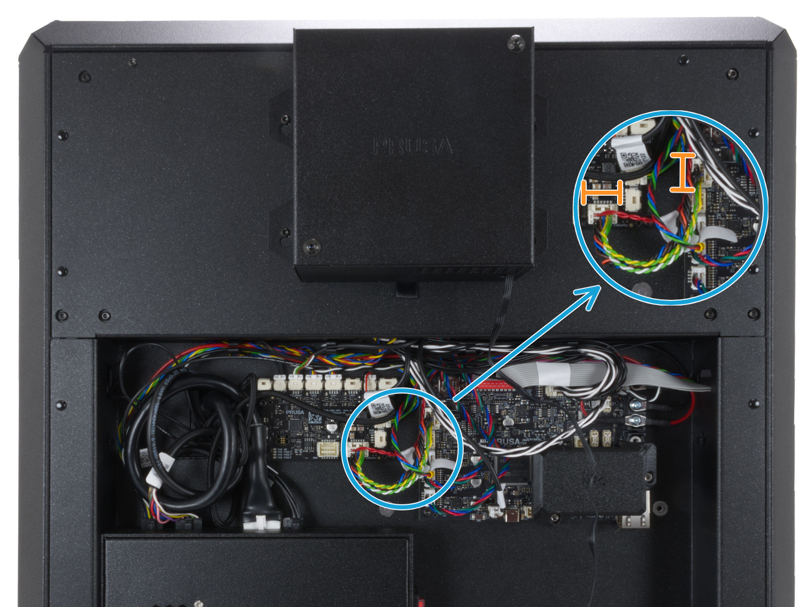
Access xBuddy board and Wi-Fi board - CORE One
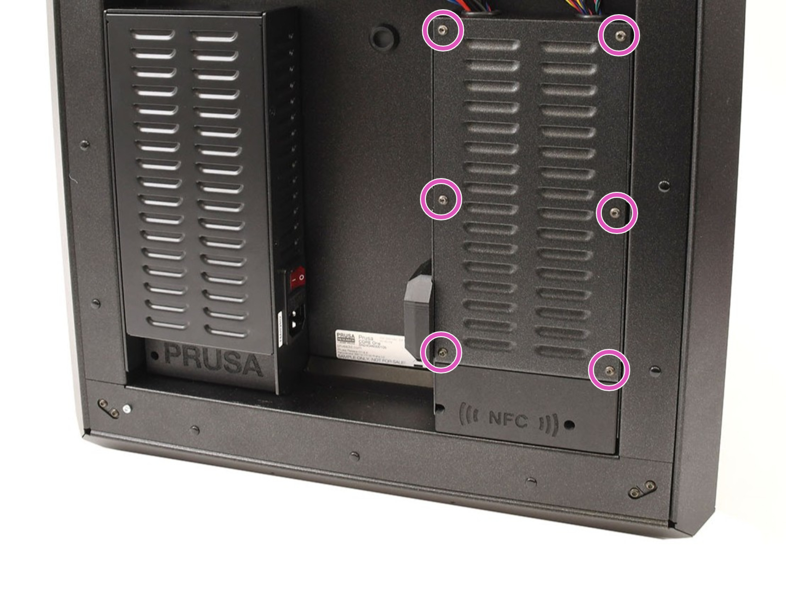
Access the xBuddy and board by loosening six M3x4bT bolts to remove the cover.
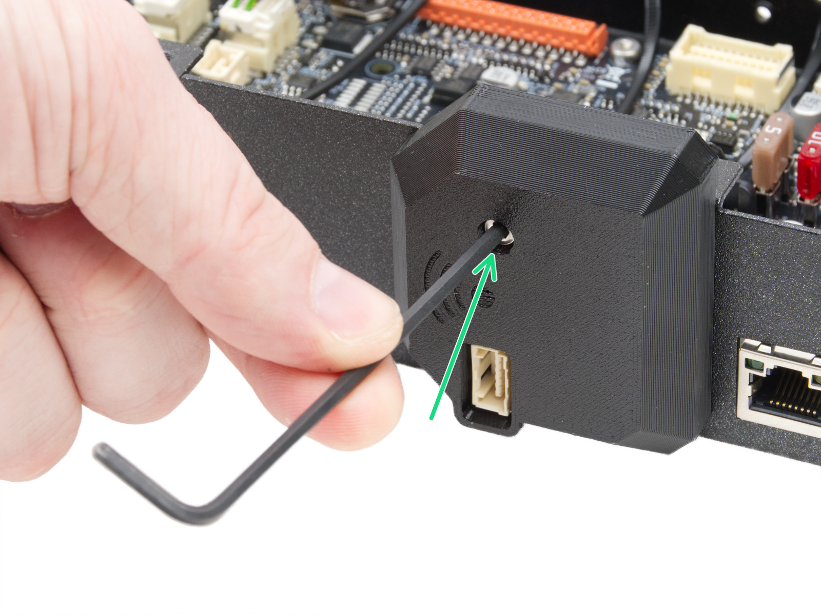
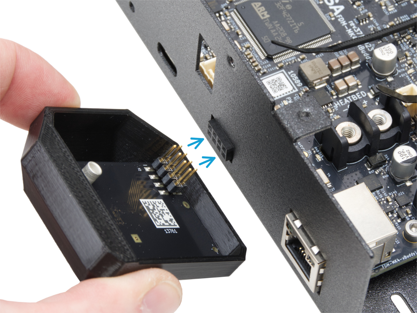
Access the Wi-Fi board by loosening an M3x12 bolt and disconnecting the board, connected by eight spikes.
 |  |
 |  |
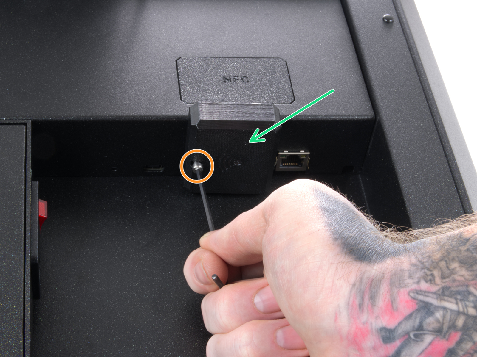
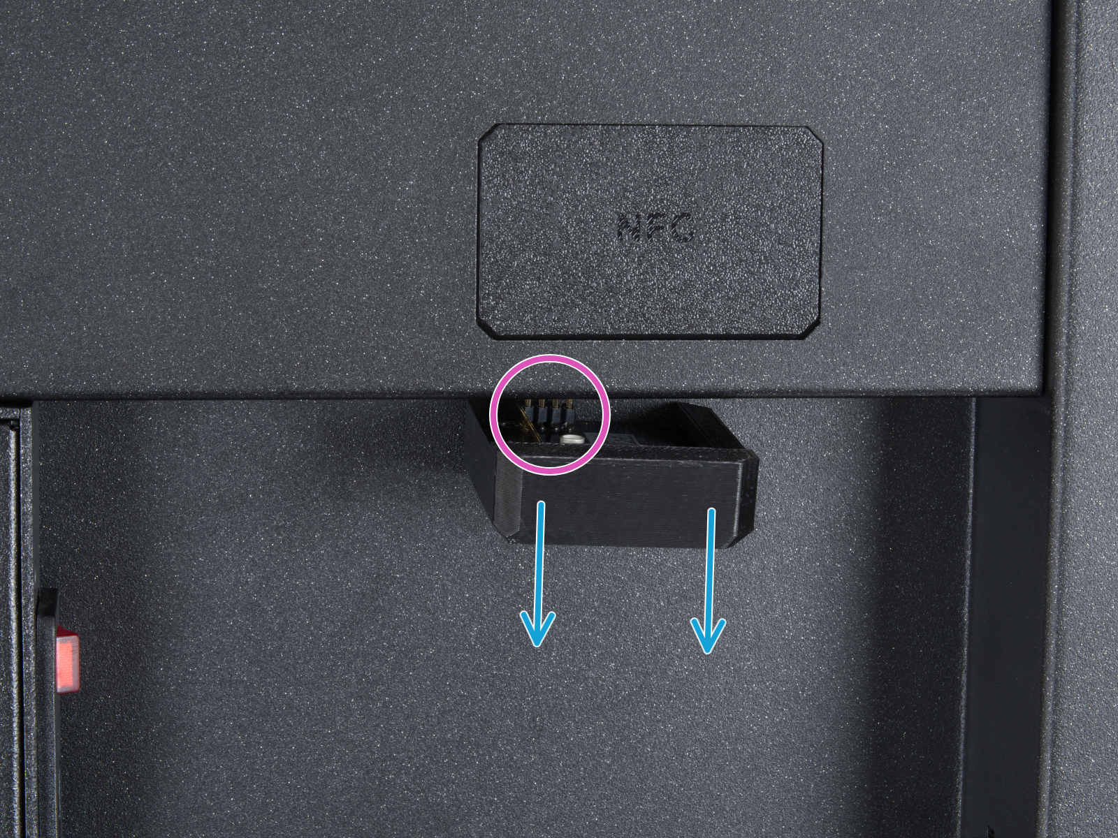
Access xBuddy board and Wi-Fi board - CORE One L
Locate the Wi-Fi module on the rear panel of the printer. Using a 2.5 mm Allen key, remove the M3x14 screw. Gently pull the Wi-Fi module straight downward to remove it from the printer. Note that the Wi-Fi module is connected to the electronics with eight spikes.
 |  |
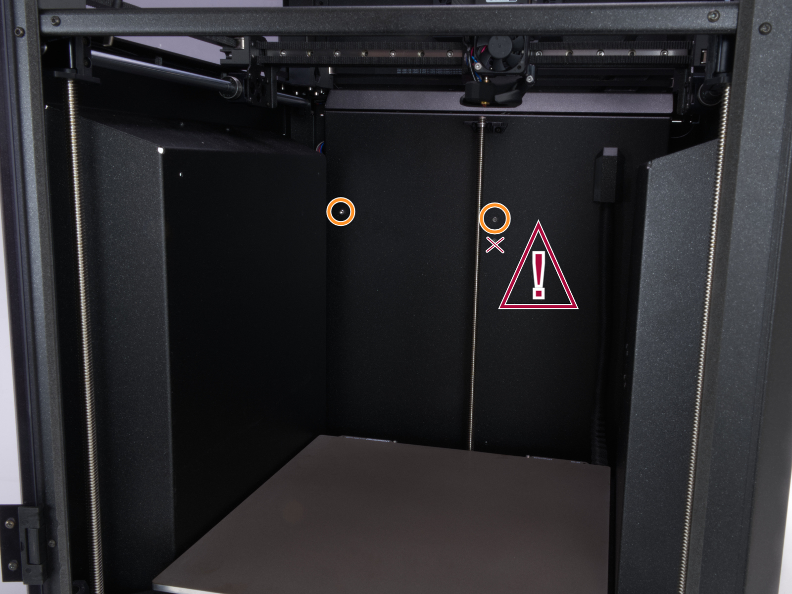
To access the xBuddy board, from the inside of the printer, locate on the rear side the highlighted M3x4bT bolts.
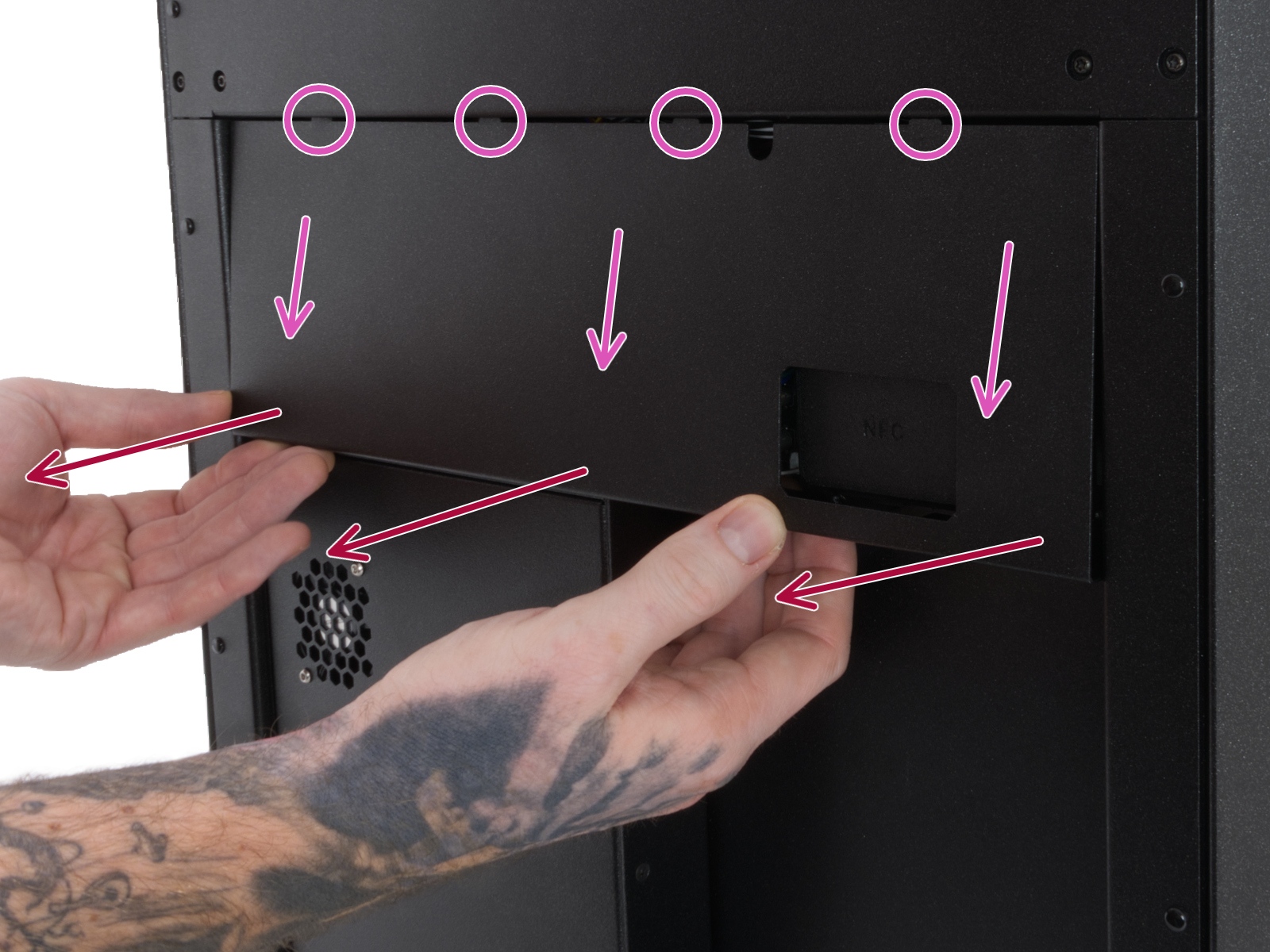
Using a T10 Torx key, remove two M3x4rT bolts to release the rear xBuddy box cover. Lift the cover to expose the xBuddy and xBuddy extension boards.
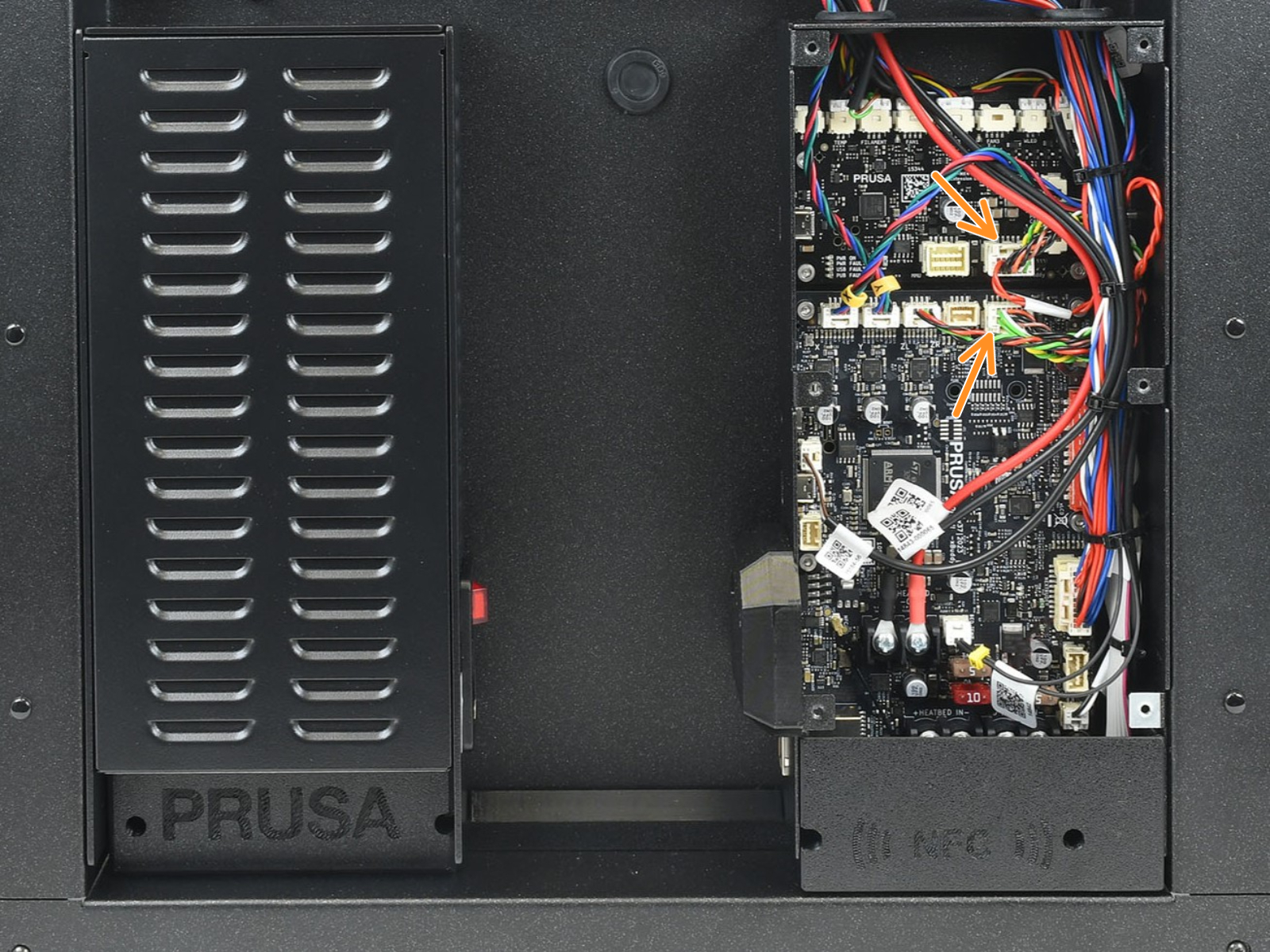
Once visible, check the boards for visible damage on their surface, and check the connection between xBuddy and xBuddy extension for any irregularities.
 |  |
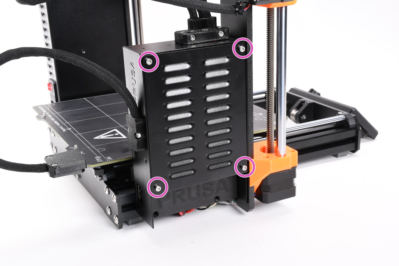
Access xBuddy board and Wi-Fi board - MK4S, MK3.9S
Access the xBuddy board by loosening four M3x6 bolts.
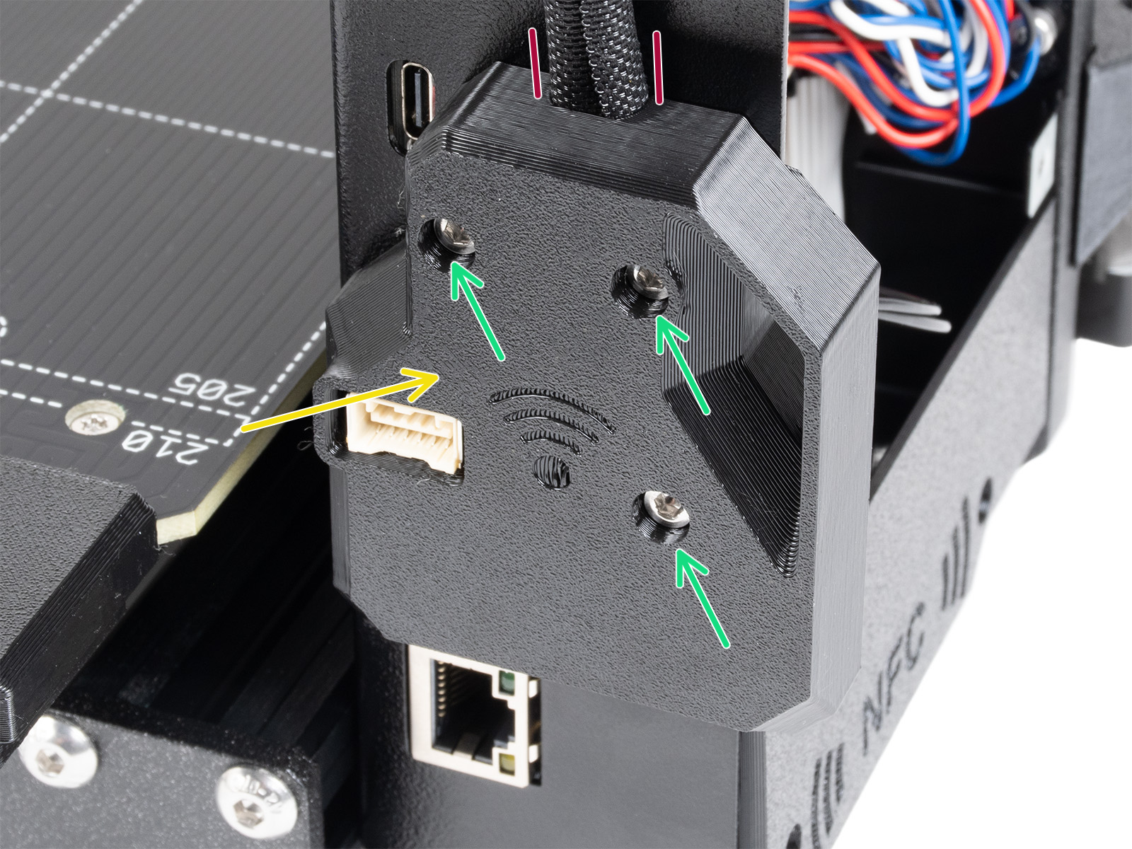
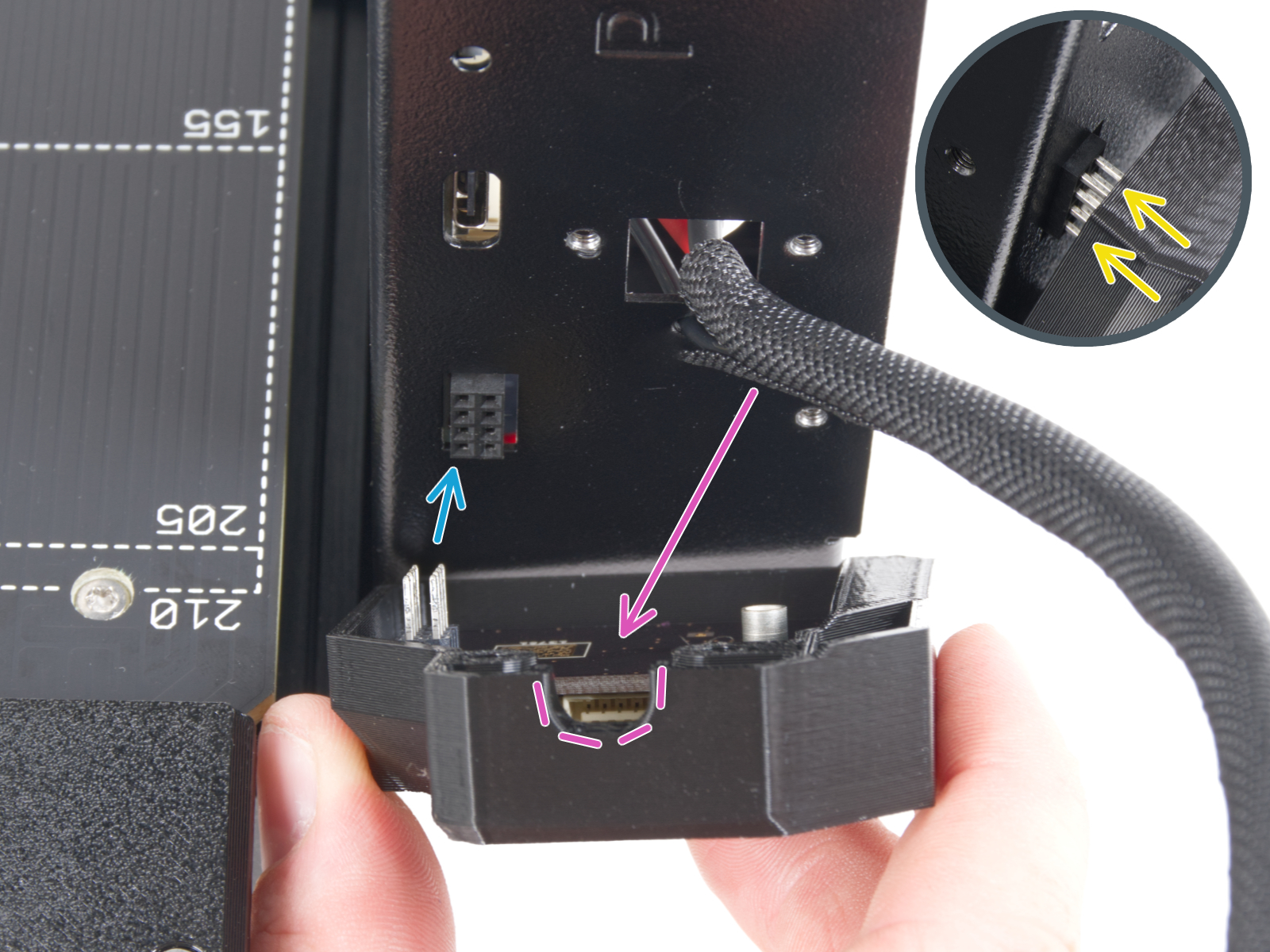
On MK4S and MK3.9S, access the Wi-Fi board by loosening three M3x12 bolts, and disconnecting the board, connected by eight spikes.
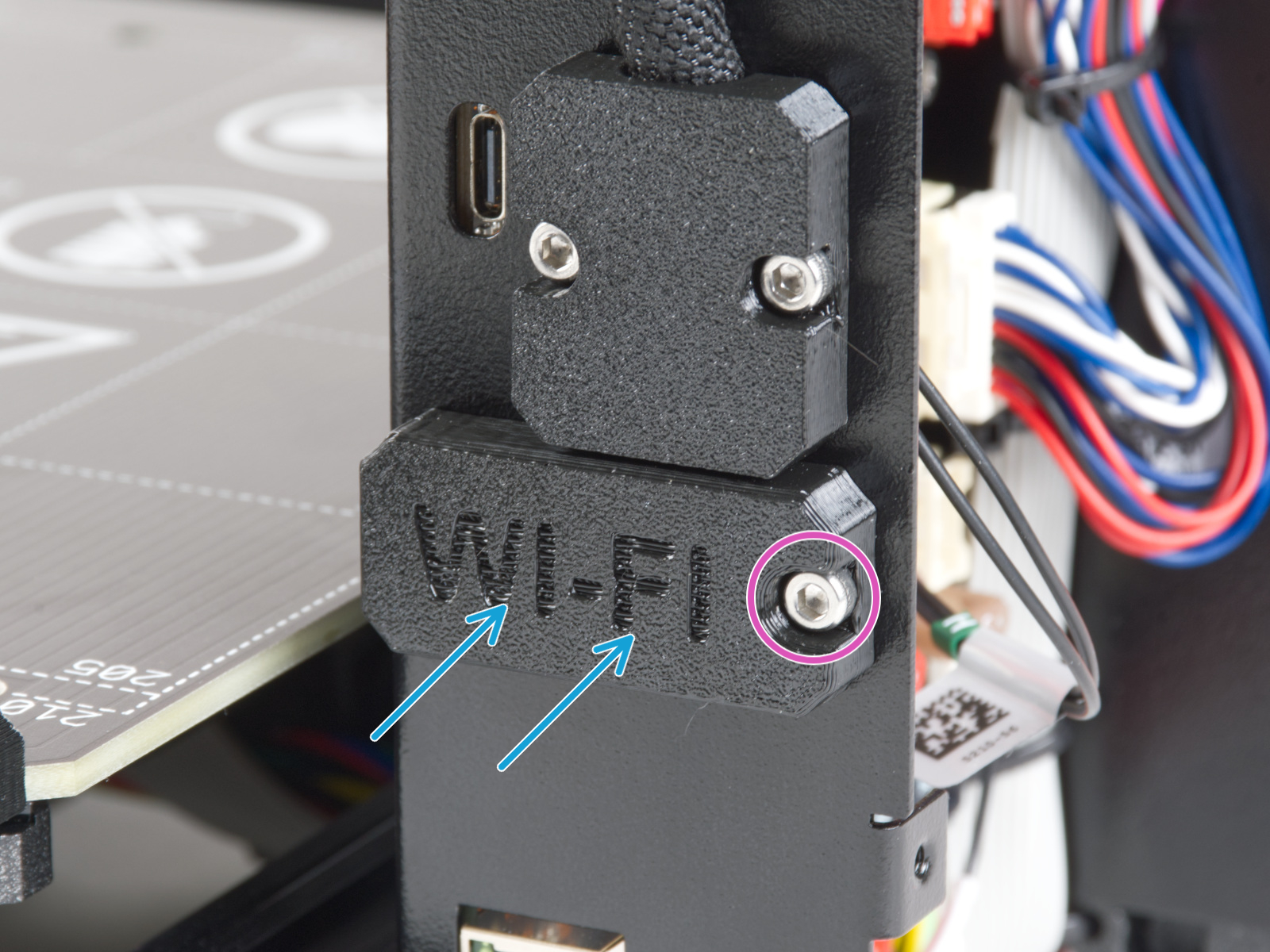
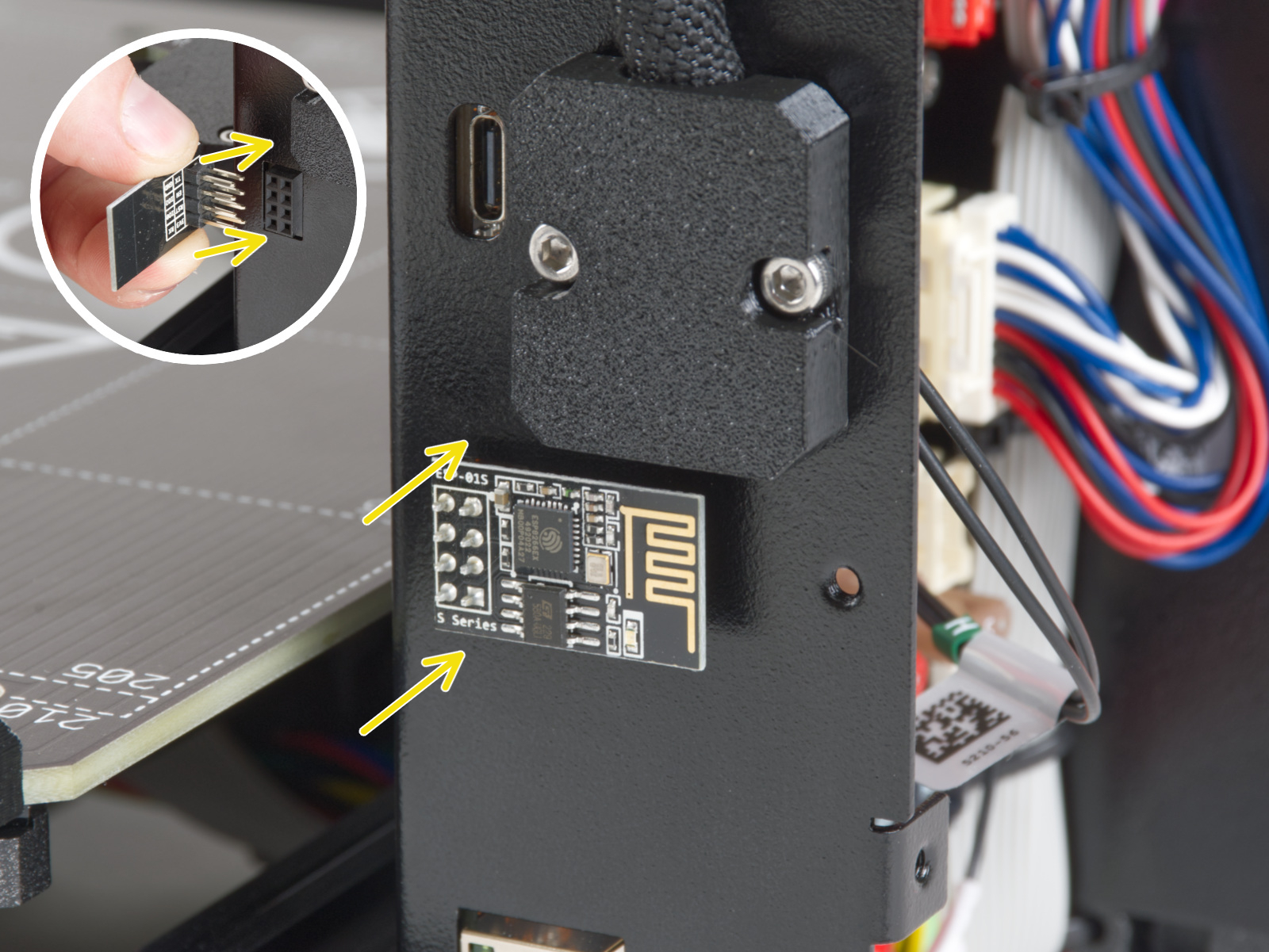
On MK4 and MK3.9, access the Wi-Fi board by loosening one M3x6 bolt, and disconnecting the board, connected by eight spikes.
 MK4S, MK4, MK3.9S, MK3.9
 |  |
| MK4S, MK3.9S | MK4S, MK3.9S |
 |  |
| MK4, MK3.9 | MK4, MK3.9 |
Are you still having issues? Contact our support team and let them know that you tried to fix the issue with these instructions. We will take it from there.