If you have the Original Prusa MMU2S or MMU3 installed in the MK3S/+ or MK3.5, the IR filament sensor needs to be calibrated before first use, in order to work properly. The calibration of the IR sensor is based on the position of the chimney (IR sensor holder) on the extruder. This calibration is purely mechanical.
Without calibrating the IR filament sensor, false readings from the sensor can occur.
For example, if there is no filament inserted in the extruder, it is possible the sensor assumes the opposite. In a similar way, even during a print when the filament is in the extruder, it is possible the sensor suddenly stops registering it. It might then trigger filament change, or the 'Spool join' feature if you have it enabled.
MMU3 calibration procedure
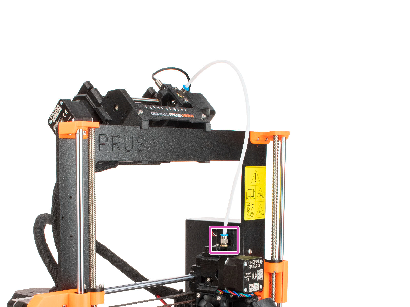
- Unscrew the Festo fitting of the PTFE tube leading from the MMU to the extruder.
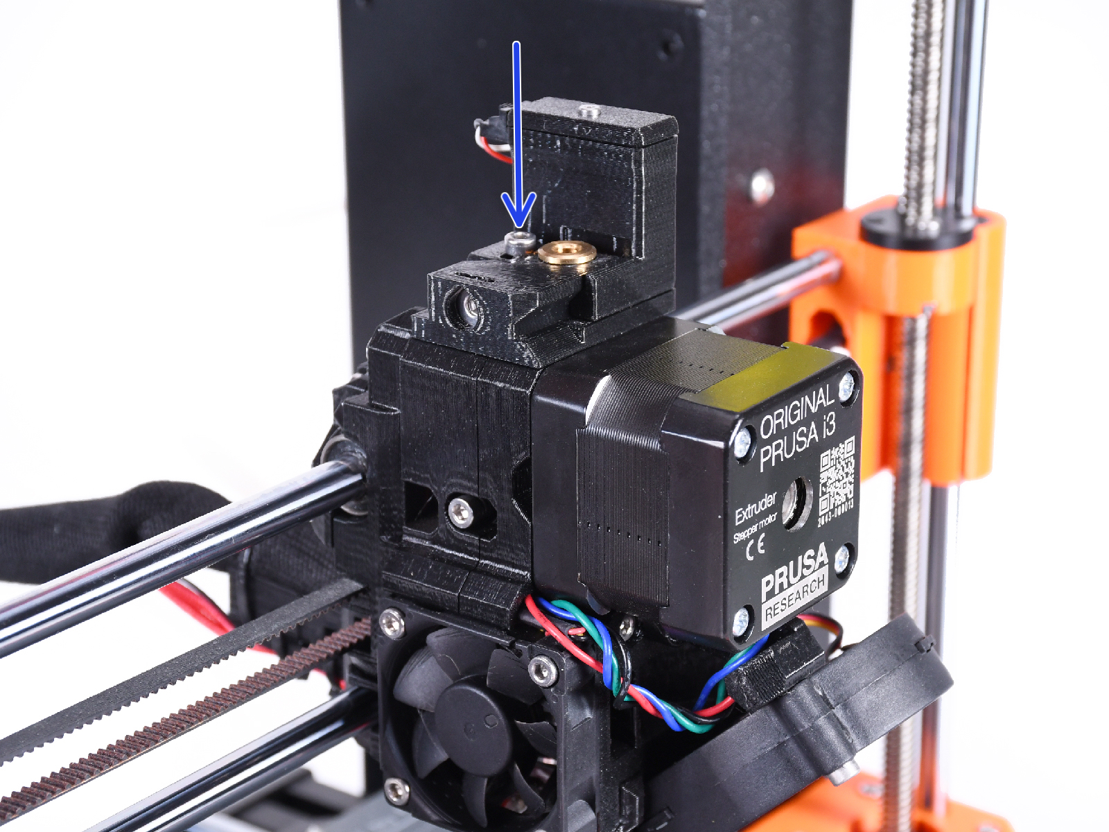
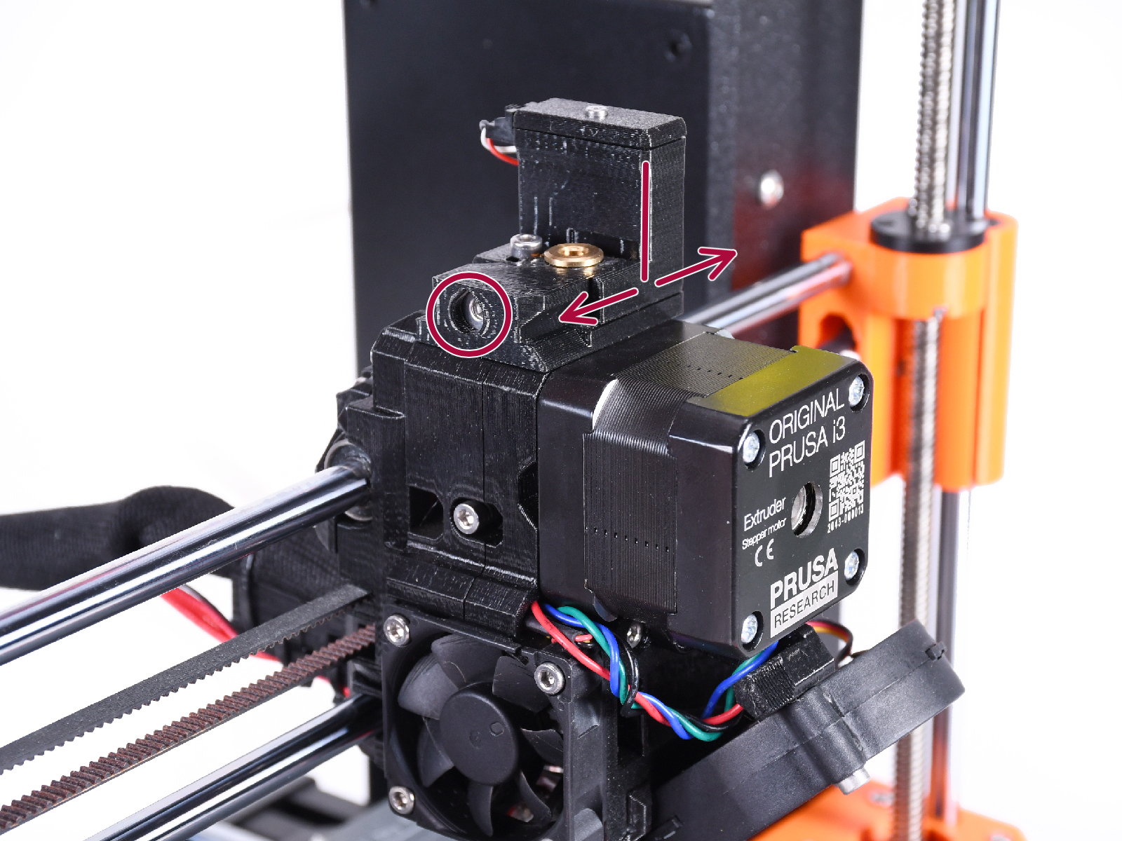
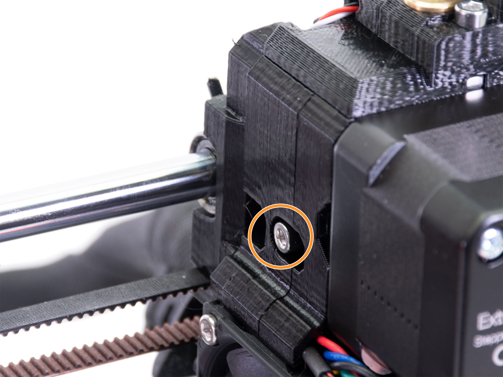
- Identify the lock screw on the chimney. Using a 2.5mm Allen key, loosen the lock screw, without removing it.
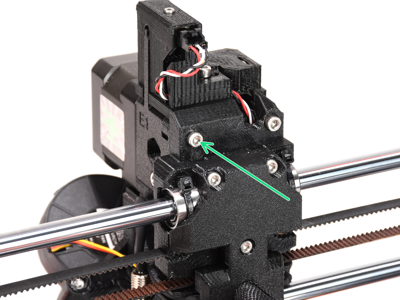
- Carefully tighten the calibration screw on the side so that the chimney moves all the way to the left.
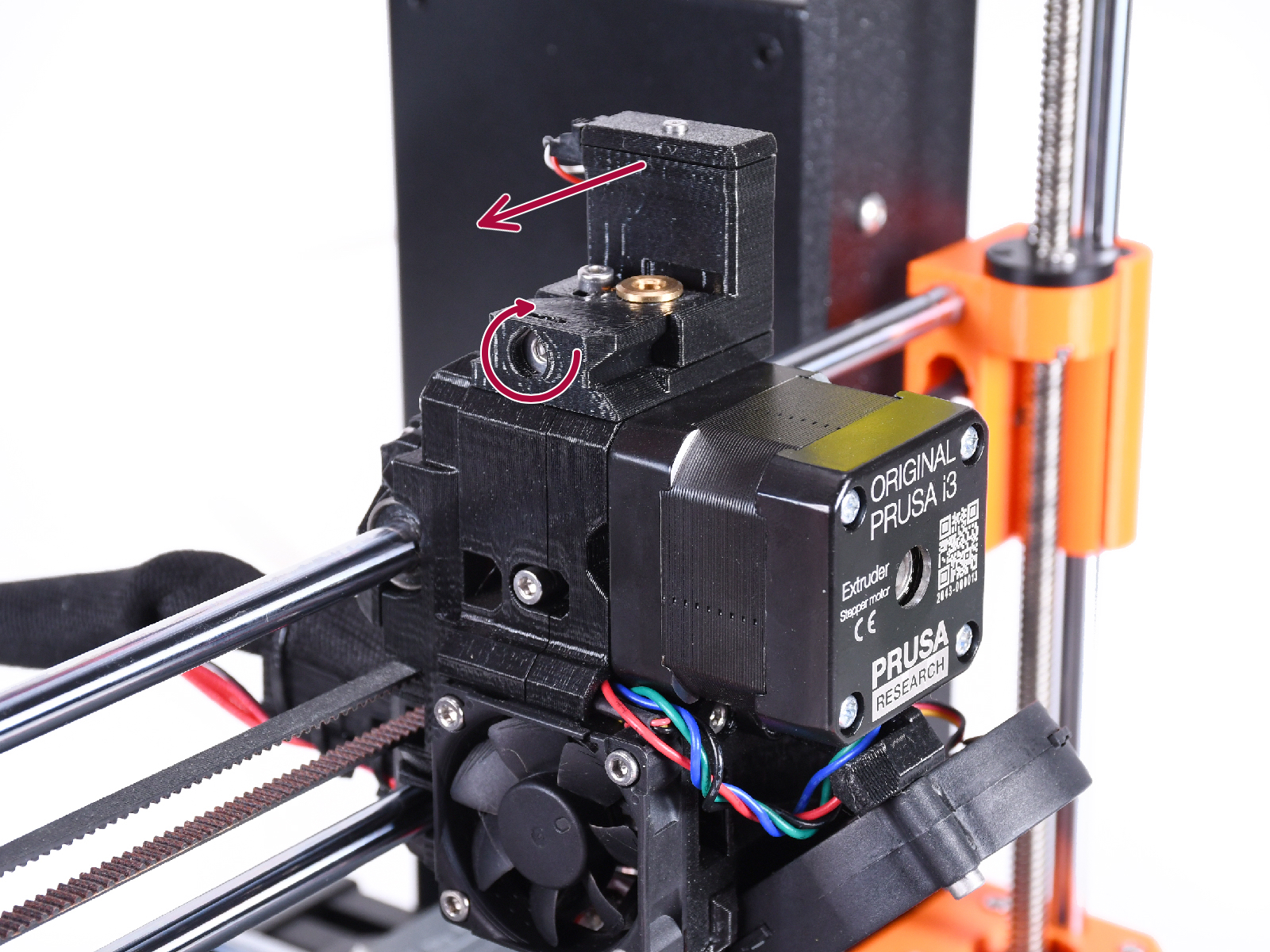
- Tightening the calibration screw moves the chimney to the left.
- Loosening the calibration screw moves the chimney to the right.
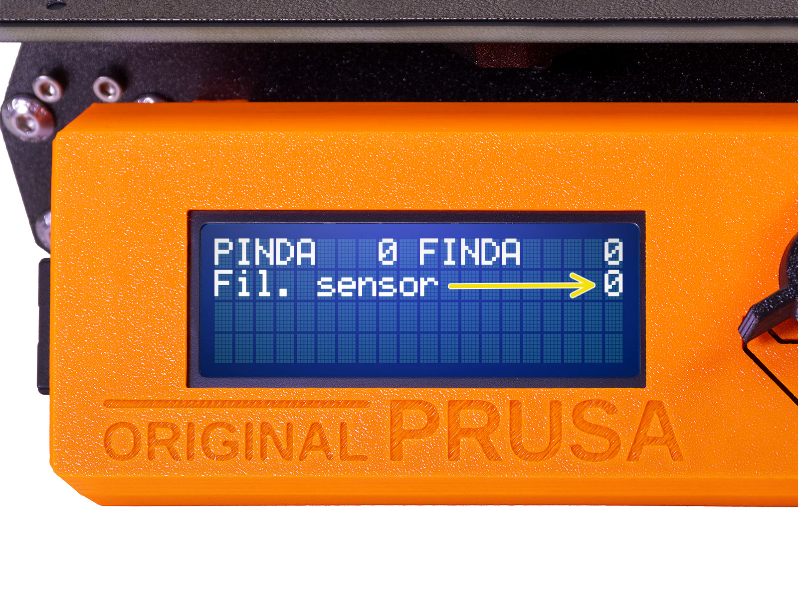
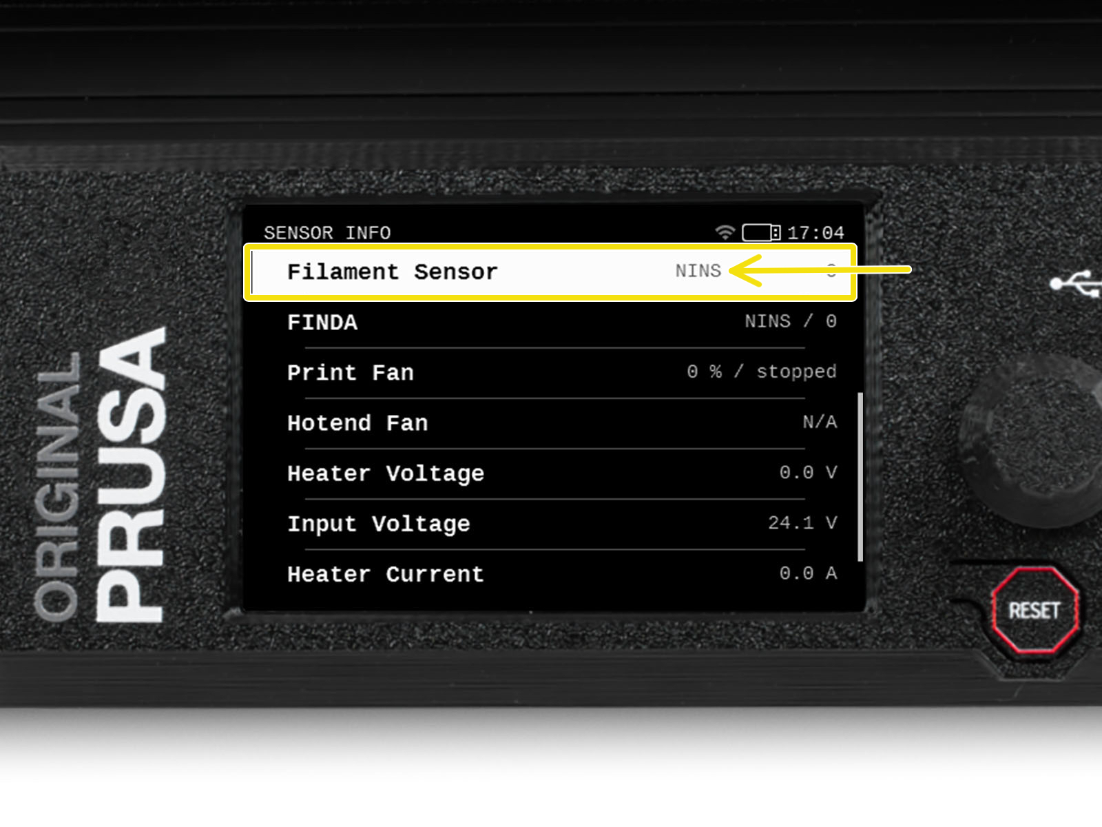
- Open the LCD menu -> Support -> Sensor info (MK3S+), or LCD menu -> Info -> Sensor Info (MK3.5) and check the value of the filament sensor. The value is expected to be NINS if the filament is not inserted, and expected to change to INS whenever the filament is inserted in the print head.
- Insert the smallest 1.5 mm Allen key (ideally the long one included in the MMU kit) instead of a filament into the extruder (without preheating), push it in between the Bondtech gears to move the lever (don't be afraid to apply a fair amount of downward force in order to get the key in between the gears). The filament sensor value is expected to change to 1/INS.
- By rotating the calibration screw, we need to fine-tune the chimney position so that the number on the LCD reliably changes when inserting and removing the Allen key or filament from the Bontech gears.
- Verify the readings on the LCD are still correct when inserting and removing the Allen key.
MMU2S calibration procedure
First of all, make sure your printer is running on firmware version 3.6.0 or higher. You should be always running on the latest firmware version for your printer model.
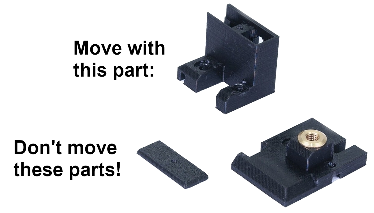
We need to calibrate the position of the chimney that houses the filament sensor. The MMU2S modification of the MK3S extruder consists of 3 plastic parts: the FS-cover-mmu2s, the IR-sensor-holder-mmu2s, and the IR-sensor-cover-mmu2s. During the following procedure, move only with the IR-sensor-holder-mmu2s, for simplicity, we will continue calling this specific part "the chimney".
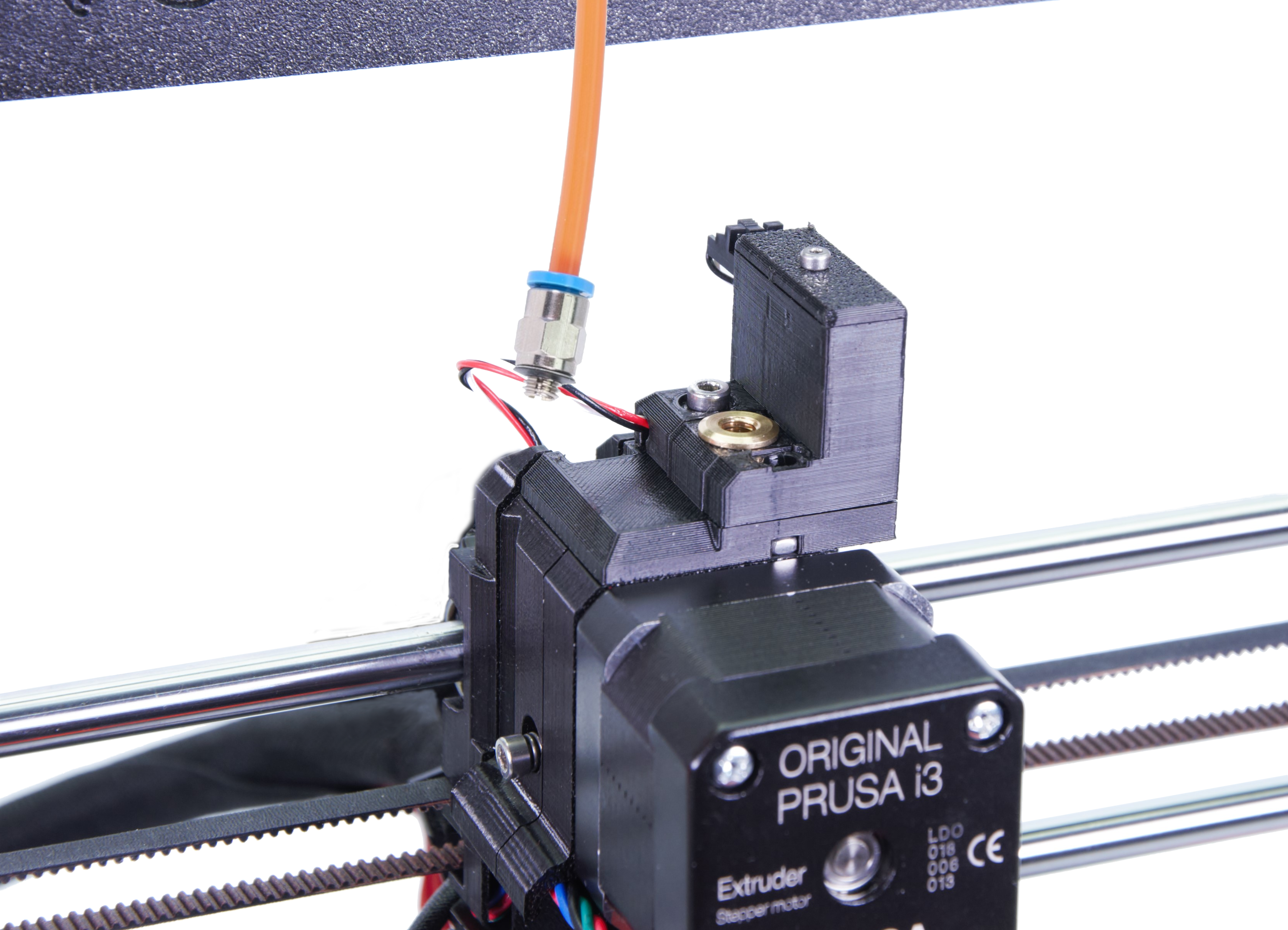
- Unscrew the Festo fitting of the PTFE tube leading from the MMU to the extruder.
- Open the LCD menu -> Support -> Sensor info and focus on the Fil. Sensor.
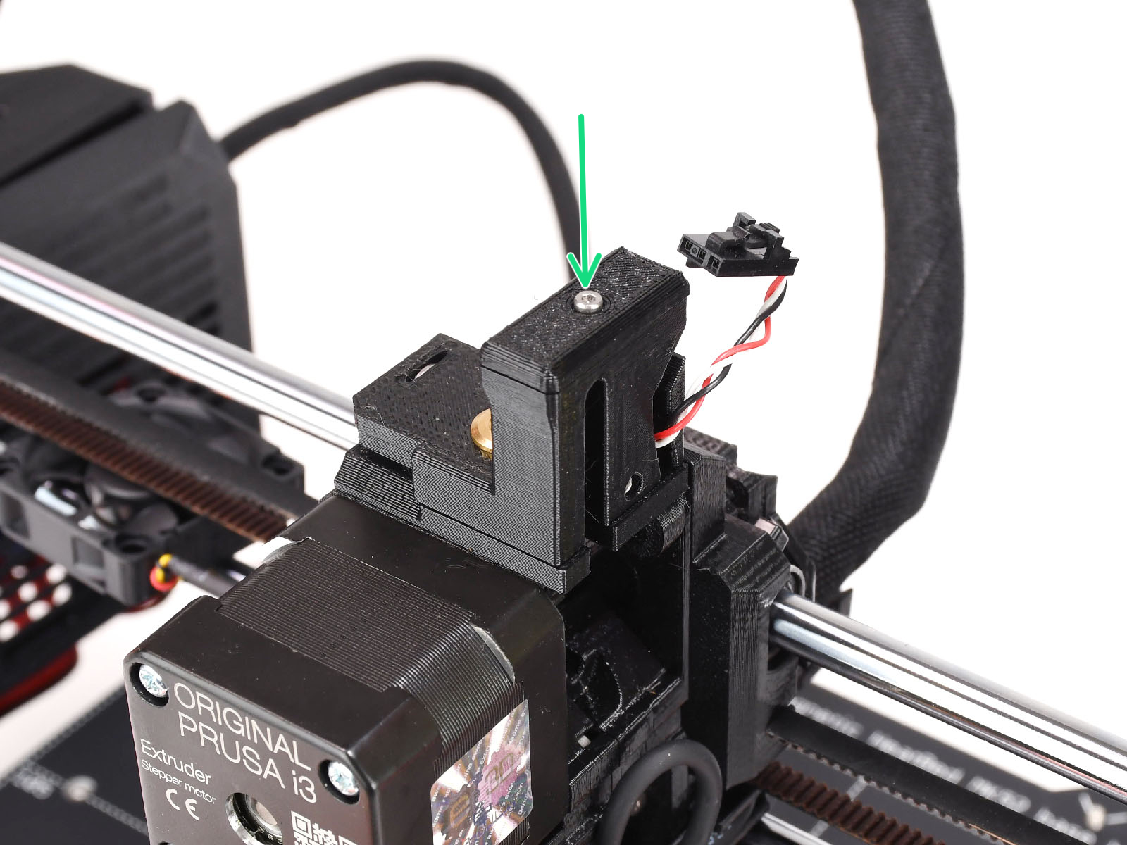
- Loosen both M3 screws on the chimney. Move the chimney as far left as possible until the IR value (Fil. Sensor) is 0.
- Tighten the M3 screws on the chimney.
- Insert the smallest 1.5 mm Allen key (ideally the long one included in the MMU kit) instead of a filament into the extruder (without preheating), push it in between the Bondtech gears to move the lever (don't be afraid to apply a fair amount of downward force in order to get the key in between the gears). If the IR sensor (Fil. Sensor) value turns to 1, the calibration is done correctly.
- If the IR sensor (Fil. Sensor) value stays at 0, pull out the Allen key from the extruder. Loosen the M3 screws on the chimney and move the chimney a tiny little bit to the right. Return back to step 4.
What if it does not work
The following checks are valid for both MMU2S and MMU3 unless specified otherwise.
- If the value is stuck on either 0 or 1 and it does not change, you may have overtightened the M3x40 screw that serves as the axle of the idler door. Try to loosen it a little bit.
- Check the extruder idler screw tension. Hold the idler with one hand while you tighten the tension screw from the other side. The screw head should be aligned or slightly below the surface. That way, the idler is pulled with the correct amount of force.

- Another screw that must not be overtightened is the M2x8 screw going through the IR sensor. Try to loosen it a little bit if it's screwed in tight, or, alternatively, tighten it if the sensor board is loose.
- Also, check if your IR sensor PCB is not loose. If it is, it can slightly rotate around the screw which can influence the readings. The IR sensor board must be perpendicular to the lever.
- In case the sensor keeps showing 1 even though the chimney is pushed all the way to the left, you first should make sure the filament was unloaded and changed correctly. Make sure the Bondtech gear is aligned.
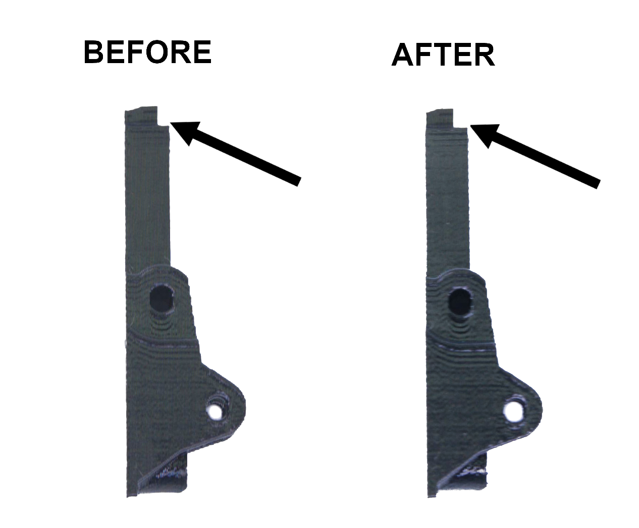
- On MMU2S, it might be necessary to cut a small dent (roughly 0.5 mm) at the top of the lever with an Exacto knife. Do not remove more than 2 or 3 filament layers! It is very easy to clean up too much for the sensor to be functional, in which case you must print a new idler. Consider having a spare before doing so, or you must disconnect both the power and signal cable of the MMU2S to use the printer in single filament mode.
26 comments
Prusa makes an effort to correct design flaws only until the next model comes out, and then users are abandoned and left behind with all the design problems in their printers.
This is the primary reason I did not consider Prusa for my last printer and went elsewhere.
Had “rough start” with mmu but now it works flawlessly but can’t get rid of that warning message after EVERY print.
Thx
After I had a problem with this solved weeks ago, I still getting the message: "Printer has detected multiple consecutive filament loading errors. We recommend checking the extruder." And still have not had a single loading error in weeks, I'm not getting rid of this message. How can I reset the error counter leading to this message?
Edit: I found it. Go to Hardware --> Printhead --> Nextruder Maintenance.