What happened?
The Original Prusa MINI/+ displays the message: "Failed to home the extruder in X-axis, make sure there is no obstacle on X-axis".
Error name: Homing error X
Error code: #12304
The error is most likely caused by a bad movement of the print head along the X-axis.
How to fix it?
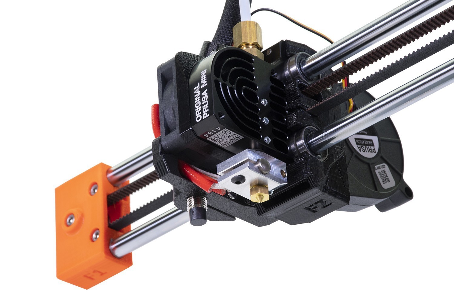
X-axis movement
Make sure there are no obstructions in the path of the X-axis. For example, there might be a piece of filament stuck around the belt, or on a smooth rod, from a previous print.
X-axis belt tension
Check the X-axis belt tension and adjust it, following our dedicated article on belt adjustment.
X-end assembly
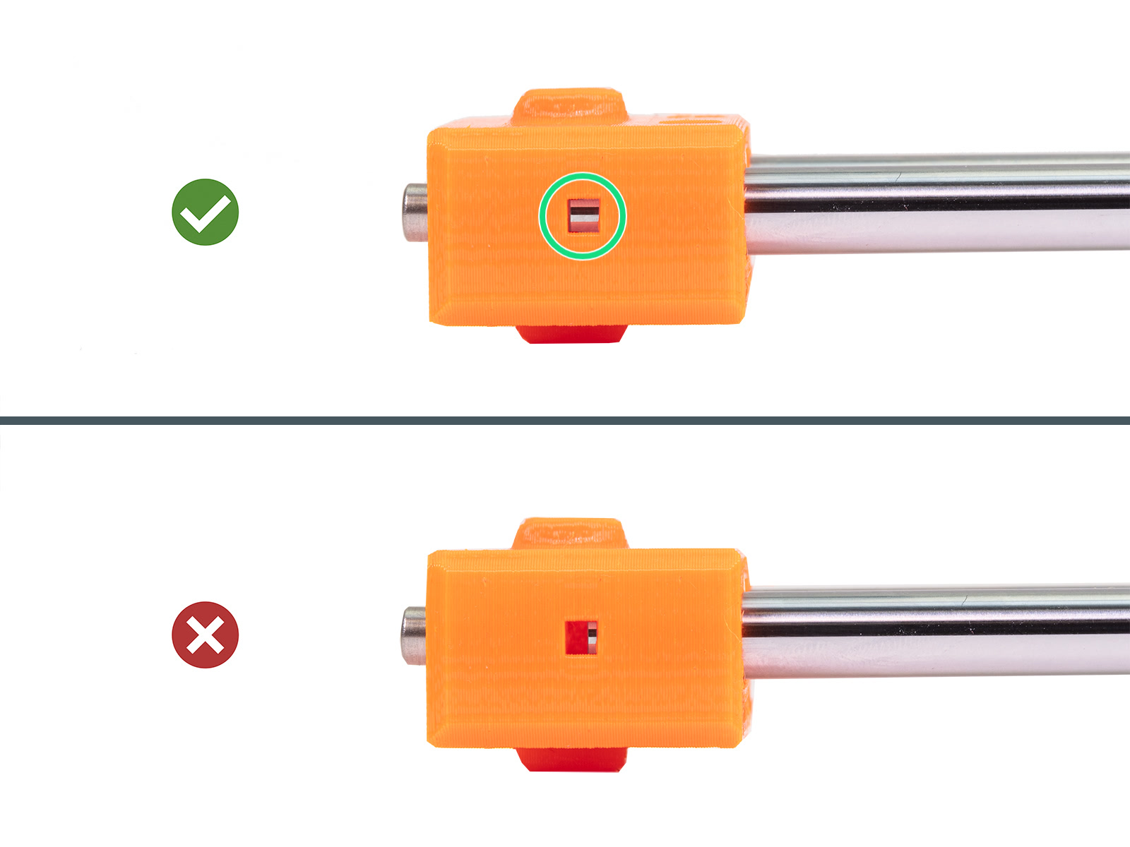
Check whether the X-end is fully inserted onto the smooth rods. Look sideways on the X-end into the inspection hole and ensure that the smooth rod is inserted all the way into the plastic part. Repeat this check for the other X-axis smooth rod.
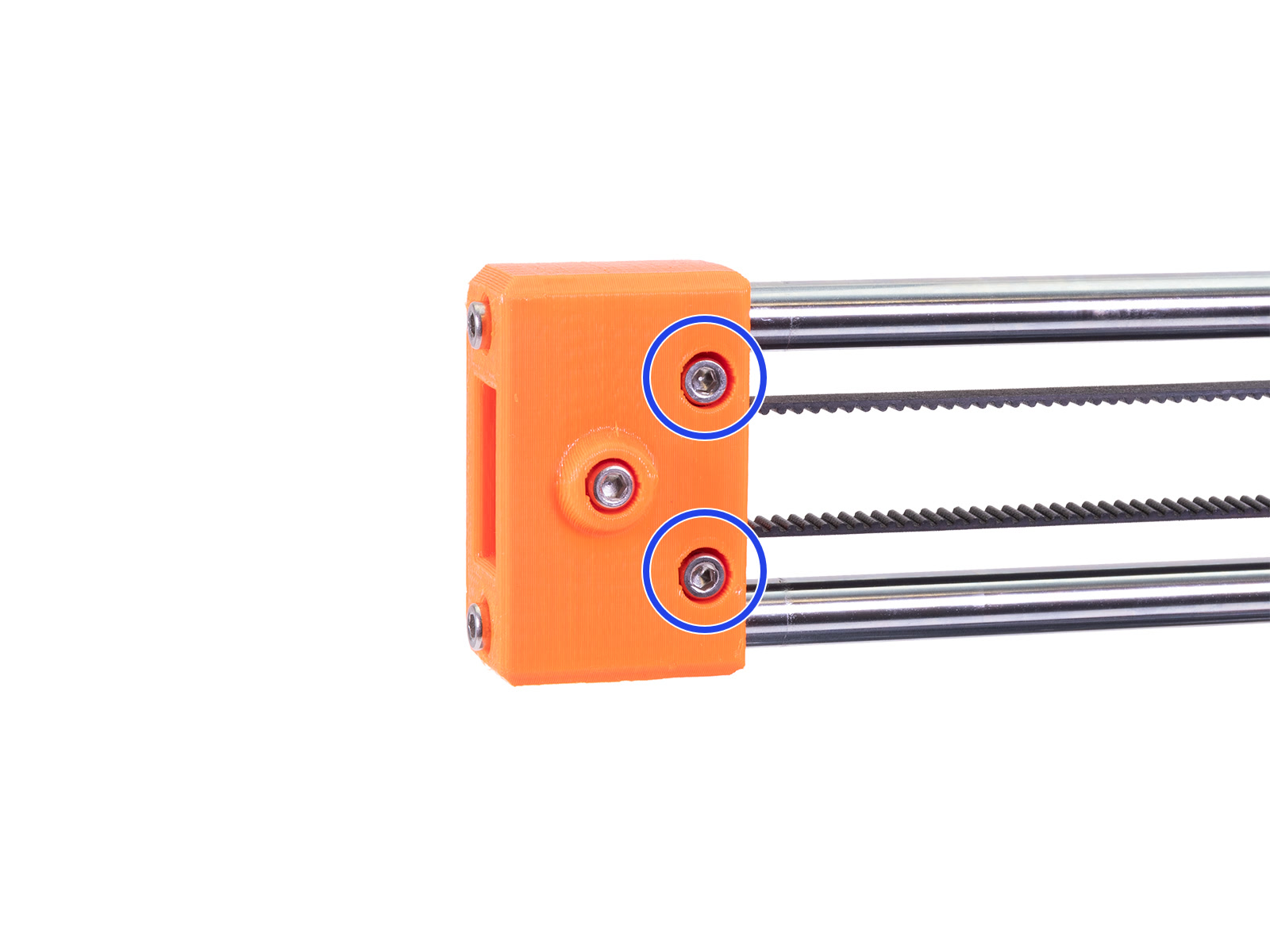
Ensure that the two screws that secure the X-end are not loose. If they are not flush or below flush with the X-end, they obstruct the full X-axis range of motion, possibly causing the error.
X-axis motor pulley
The X-axis motor pulley is attached to the X-axis motor shaft. The motor shaft has one flat side. The pulley has two set screws, ensure that one of the two set screws is aligned with the flat part of the motor shaft. Make sure the other set screw is also tightened, not excessively, and that there is a small space between the pulley and the motor.
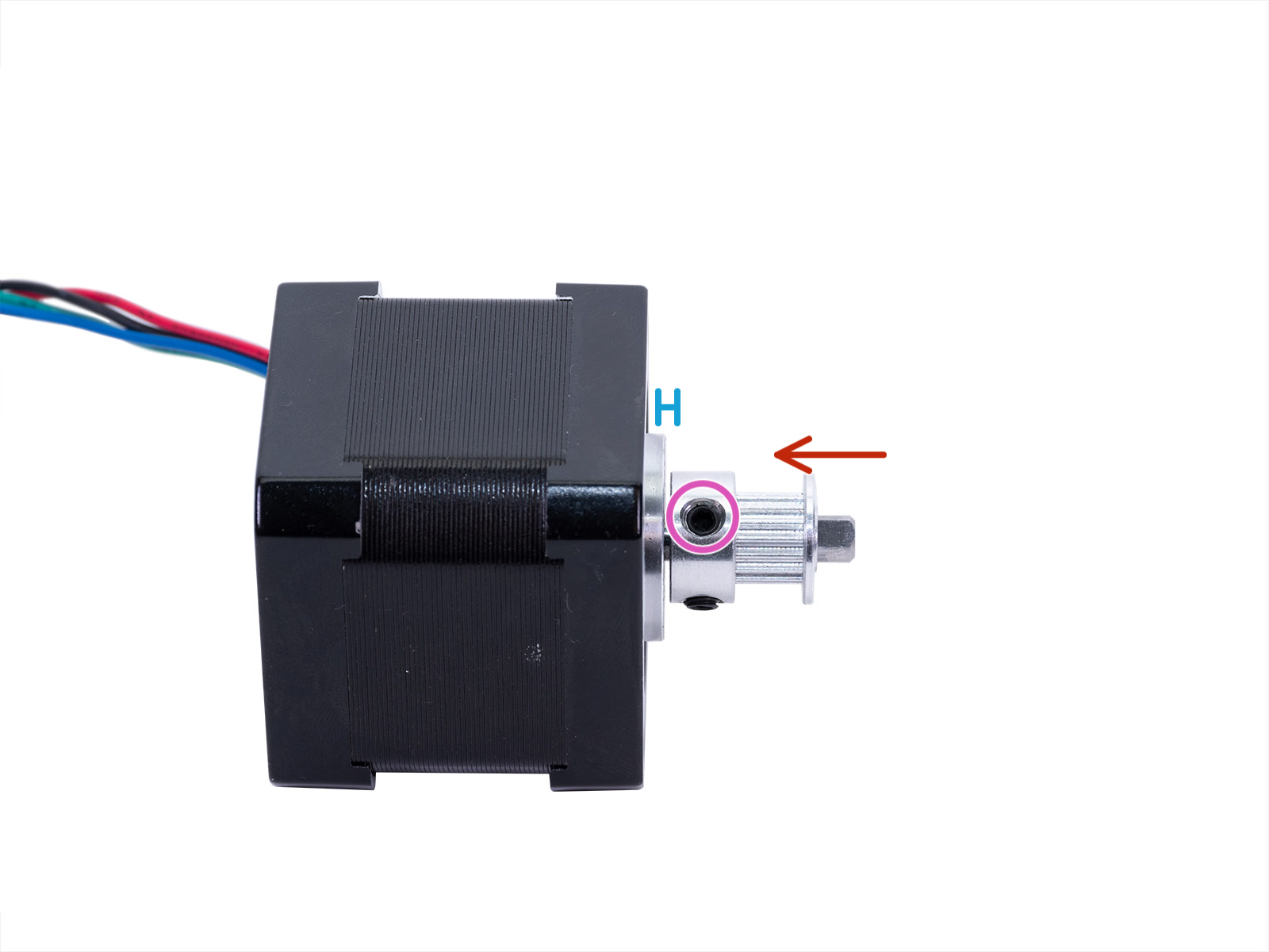
Isolated X-axis motor with attached motor pulley.
To access the X-axis motor pulley, follow these steps:
- Loosen the upper M3x25 screw. The inspection-door might come loose, remove it temporarily.
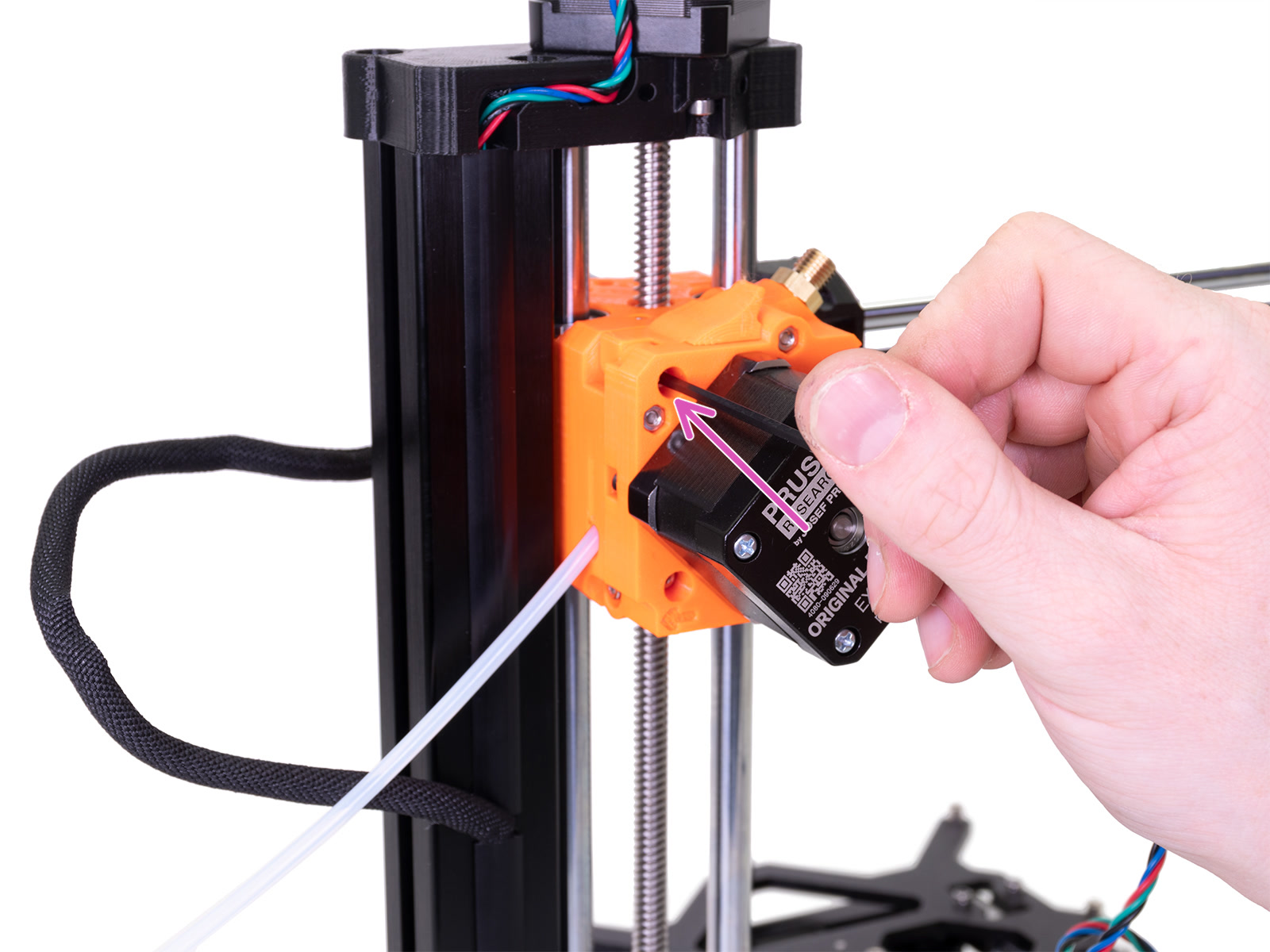
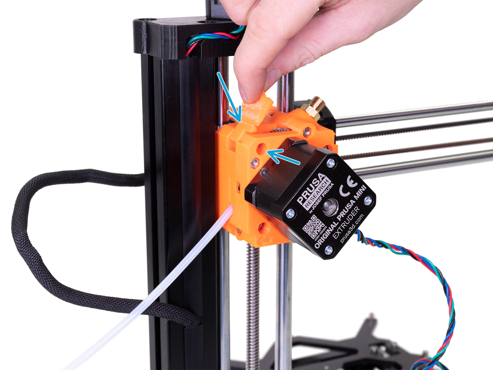
- Hold the parts with your free hand! Loosen the lower M3x25 screw, and remove the extruder block.
 |  |
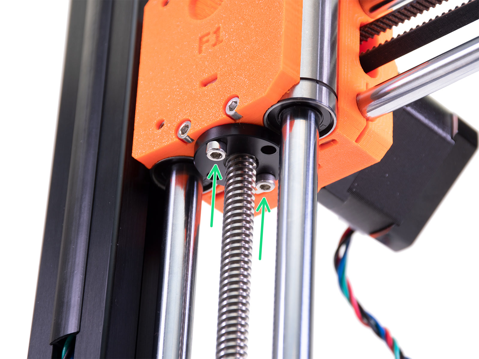
- Loosen the M3x20 screws holding the trapezoid nut.
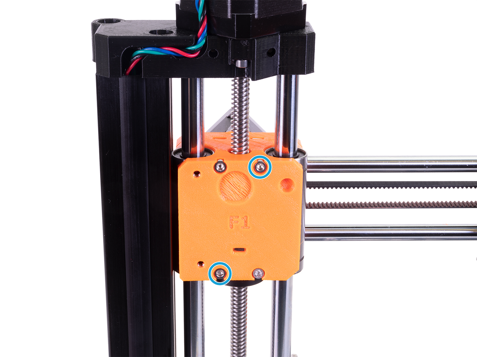
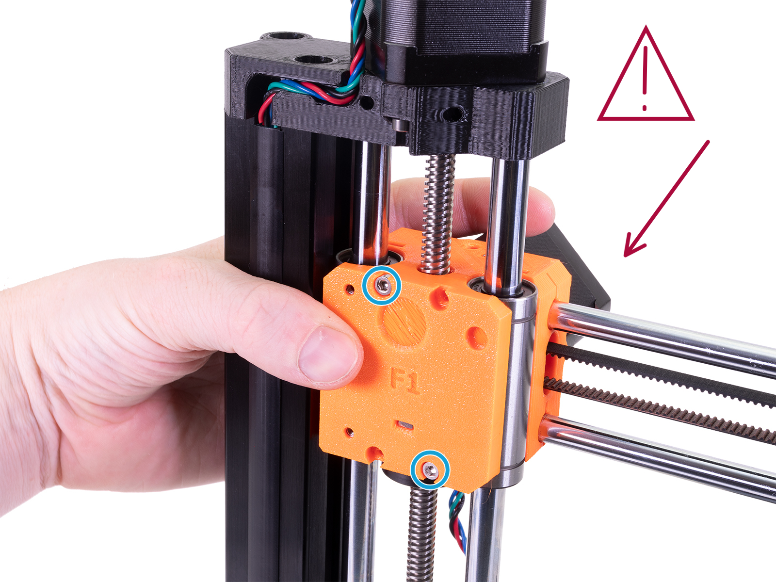
- Hold the parts with your free hand! Loosen the M3x30 screws holding the X-axis block.
- Move the print head and look into the X-axis pulley inspection hole. Stop when you see a change in the inspection hole when one of the two pulley set screws is aligned with the hole.
- Compare the set screw position with the flat part of the motor shaft.

- In case of a loose or misaligned set screw, tighten one set screw against the flat part of the motor shaft, and ensure the second set screw is also reasonably tight. Use a 2.0mm Allen key for this step.
- Reassemble the printer, by performing the above steps in reverse.
1 comment
I've had my MINI+ for about a week and i suddenly experience a plethora of problems, which i will not dive into here.
I LOVE that you have so much documentation and especially pictures of where we are on the printer and what you mean, since not everyone is fluent in english and understand all the terminology. However, my personal opinion is that some steps are missing these very helpful pictures, not only in this guide, but in general.
Namely the section with the heading "X-axis motor pulley". In this, you describe the whole process of that section, at the start, with no accompanying pictures, giving the customer the impression that they should know exactly what youre talking about. Then you've divided it into steps below, with pictures, but did not inform the customer that that was your intention. Additionally, i have no idea how to do step 5-7.
- "Move the print head" what is the print head? I've had this thing for a week, i don't know the terminology.
- "Stop when you see a change in the inspection hole when one of the two pulley set screws is aligned with the hole." I honestly have no idea what to do or look for here.
I am unable to understand the rest, because you reference stuff i don't know what is, where is or what it looks like.
I don't know if i'm unfair or maybe just stupid :)
I truly hope you will pay attention to this, as this can help us customers with self-help, giving you more time to develop the great products you make. Thanky you for all your support