関連するもの


In this section, it is possible to choose which extruder in your printer to print specific parts.
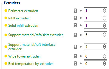
Extruder to use when printing perimeters and brim.
The extruder to use when printing infill.
The extruder to use when printing solid infill.
The extruder to use when printing support material, raft and skirt. Set to 0 to use the current extruder, which will minimize tool changes.
The extruder to use when printing support material interface. Set to 0 to use the current extruder, which will minimize tool changes. This also affects the raft.
The extruder to use when printing the perimeter of the wipe tower. Set to 0 to use the current extruder. The current extruder is preferred when using soluble supports.
This is the extruder that determines the heatbed temperature. Set to 0 to determine the temperature based on the first printing extruder of the first and second layers.
Enabling Ooze prevention drops the temperature of the inactive extruders to prevent oozing.

Temperature difference to be applied when an extruder is not active. The value is not used when "Idle temperature" in filament settings is defined.
Read more about the wipe tower settings here: 糸引きと垂れ.
The features here help to create a strong well-bonded multi-material print by improving their strength and reliability.
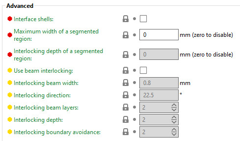
Force the generation of solid shells between adjacent materials/volumes. This is seful for multi-extruder prints with translucent materials or manual soluble support material.
Maximum width of a segmented region. Zero disables this feature.
This feature cannot be used when "Use beam interlocking" is selected.
Maximum depth of a segmented region. This feature is disabled if the value is zero, if the "Maximum width of a segmented region" is zero, or if a value higher than "Maximum width of a segmented region" is used.
This setting improves adhesion between painted color/material patches and helps prevent separation between colors. This is especially useful for models painted or merged in the slicer rather than split into separate physical meshes
This feature cannot be used when "Use beam interlocking" is selected.
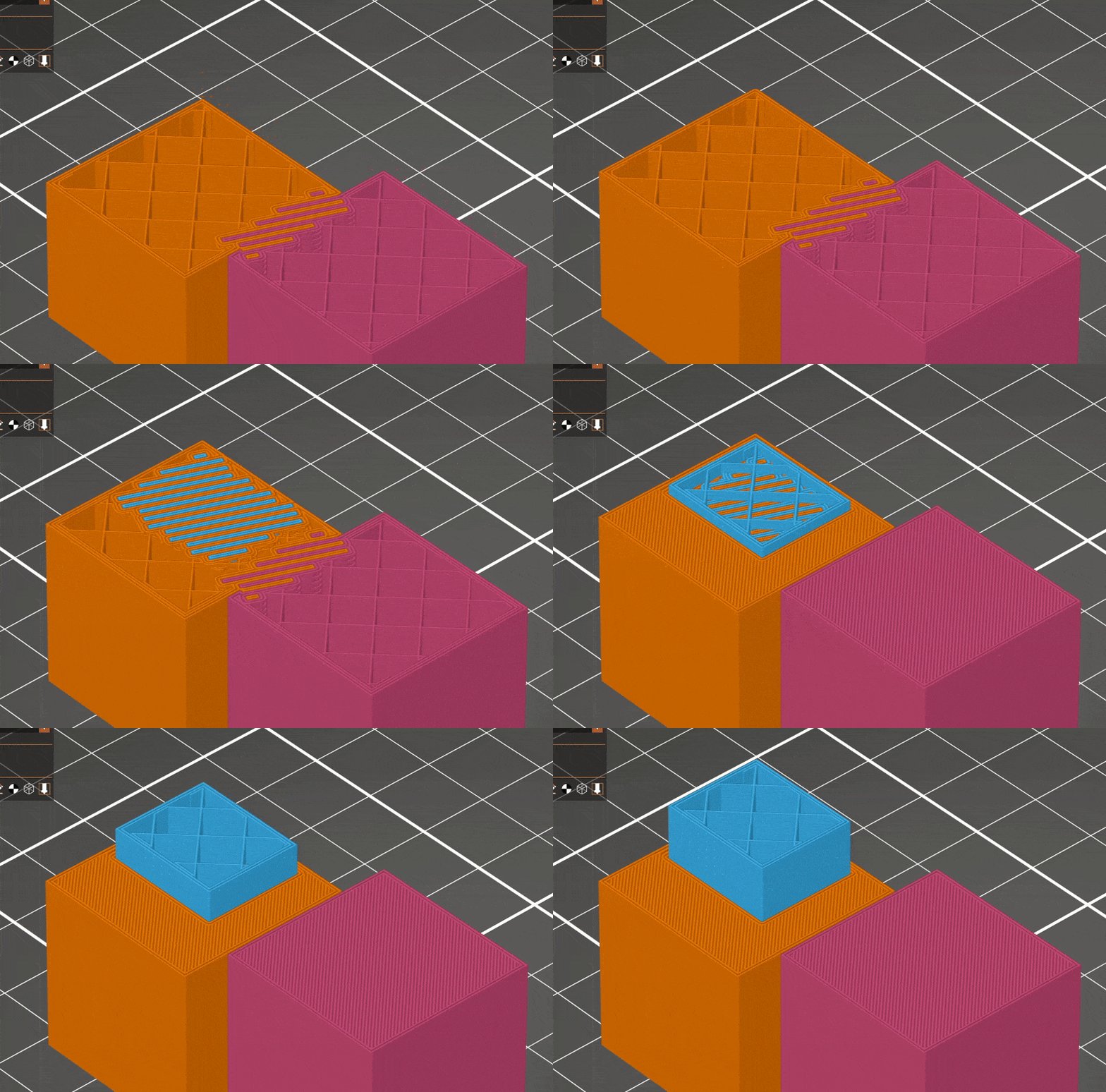
Enable this feature to create internal cross-hatched beams at material boundaries to strengthen their bond. It works for face-to-face touching volumes, overlapping volumes, and painted regions with assigned materials. It is also useful when mixing materials and when printing structural parts with embedded flexible or soft sections.
This feature is disabled by default.
The width of the interlocking structure beams.
Orientation of interlocking beams.
The height of the beams of the interlocking structure, measured in number of layers. Using fewer layers will make the connection stronger but more prone to defect.
The distance from the boundary between filaments to generate the interlocking structure, measured in cells. Too few cells will result in poor adhesion.
The distance from the outside of a model where interlocking structures will not be generated, measured in cells.