AA

おすすめ製品

    人気のカテゴリー

      急上昇ワード

        記事

          ブログ

            製品

              カテゴリー

                検索候補

                  検索中…
                  結果がありません
                  エラーが発生しました。
                  ↑↓ 選択↵ 開くEsc 検索を閉じる
                  • English
                  • Čeština
                  • Deutsch
                  • Español
                  • Français
                  • Italiano
                  • Polski
                  • 日本語
                  • 注文
                  • 住所
                  • 在庫ありのアラート
                  • 講座
                  • サブスクリプション
                  • アカウント編集
                  • 3Dプリンター9+▾

                    3Dプリンターnew

                    newPrusa CORE One Lさらに詳しく
                    newPrusa CORE One+さらに詳しく
                    newPrusa CORE One L+ INDX 8-ToolnewPrusa CORE One+ (Gen 2) INDX 8-ToolPrusa CORE One L: Critical InfrastructureOriginal Prusa MK4SnewOriginal Prusa XLOriginal Prusa XL:クリティカルインフラストラクチャー

                    プリンターのアップグレード

                    newCORE One/+ INDX Conversion KitnewMK3S/+ から MK4SnewXL - シリコンプリンティングツールヘッドnewMMU3 (Multi Material Upgrade)
                    Prusa 報酬プログラムシェアして、紹介して、特典をゲット。
                    3Dプリンターを選び方スペース・予算・用途に合わせて最適なマシンを選ぶための基本をご紹介します。
                    無料の電子書籍無料の電子ブック Basics of 3D Printing with Josef Prusa をダウンロードして、3Dプリンティングの世界への第一歩を踏み出しましょう。
                    Original Prusa のプリント可能なパーツOriginal Prusa 3Dプリンターとアップグレード用のプリント可能なスペアパーツコレクション。
                    配送情報プリンターの現在の生産量と納期に関する情報を定期的に更新しています。
                    カスタム3Dプリント様々な素材を使用したプロフェッショナルなカスタム3Dプリントサービス。
                  • マテリアル▾

                    フィラメント

                    PrusamentPLAPETGASA / ABSPCブレンドPA (Nylon)FlexComposites特別Materials clearance sale

                    レジン

                    Prusament Resin Tough柔軟性
                    フィラメントガイドプルサメントスプールをチェック
                    Prusament.com
                  • 部品 & アクセサリー▾

                    アクセサリー

                    エンクロージャーノズルスチールシート必須アクセサリーカメラ&アドオンツール&クラフト接着剤

                    補修部品

                    商品

                    スペアパーツ - すべてのプリンターCORE OneMK4/S & MK3.9/SMK3/MK3S/MK3S+XL
                    Merch
                  • 法人向け▾
                    Prusa Pro HT90Prusa Pro SLXPrusa Pro AFSPrusa Pro Medical OneOriginal Prusa XLOriginal Prusa XL:クリティカルインフラストラクチャー
                    Prusa CORE One+さらに詳しく
                    Prusa CORE One Lさらに詳しく
                    Prusa CORE One L: Critical Infrastructure Edition クリティカルインフラ版(高セキュリティ対応モデル)

                    3Dプリンティングの用途

                    製造と研究開発自動車産業ヘルスケア教育と学術研究建築家とデザイナー映画産業重要インフラ

                    3Dプリンティングのストーリー

                    No items yet.

                    プルサ正規販売代理店
                    サステナビリティ
                    Prusa Education
                    お問い合わせ・ご連絡
                    カスタム3Dプリント
                    ISO認証取得
                  • ソフトウェア▾
                    PrusaSlicer

                    PrusaSlicerPrusaSlicer

                    PrusaSlicer は、オープンソースで機能が豊富、頻繁に更新されるツールで、3Dプリンタ用の完璧なプリントファイルをエクスポートするために必要なものがすべて含まれています。ニュースやリリースログは Github で確認できます。

                    WindowsMacOSLinux
                    Prusa Connect

                    Prusa Connect

                    Prusa Connectは、3Dプリンターの遠隔操作と監視を可能にするクラウドサービスで、安全なデータの取り扱い、簡単なセットアップ、どこからでも複数のプリンターを管理できるサポートを提供します。

                    ログインして接続する
                    Prusa.app

                    Prusa.app

                    Prusa Connect技術を活用し、どこからでもリモートでプリンターを操作可能!Prusa.appは、AndroidおよびiOSデバイス向けに新たなPrusaプリンター体験を提供します。

                    今すぐお試しください!
                    ドライバー&ファームウェア3Dプリンタの最新のファームウェアとドライバをダウンロードしてください。
                    PrusaSlicer サポート
                    Prusa Connect サポート
                  • 3Dモデル▾
                    3Dプリンターアート&デザインホビー&メーカー日用雑貨テーブルトップミニチュアおもちゃ&ゲームPrintablesストア

                    人気の3Dモデル

                    • Strong garden hose holder
                    • Prusa Spool Bot
                    • Build Tray — Modular Organizer for Assembly, Disassembly and Maintenance
                    • Broom Holder
                    • Octagon Fabric
                    • Prusa CORE One ? (Mimic Skin)

                    デザインコンテスト

                    • Framework Laptop 12 Mainboard Wiederverwendung2026/9/1 – 2026/9/30
                    • 🏆 Designer Herausforderung: Zaubertricks!2026/9/1 – 2026/9/22
                    • Make-up Aufbewahrungslösungen2026/9/4 – 2026/9/20
                  • コミュニティ▾

                    イベント情報

                    • IFA 20262026/9/4 – 2026/9/8 · Berlin, Germany · Prusa Team
                    • Maker Faire Bay Area2026/9/25 – 2026/9/27 · Kalifornie, United States · Prusa Team
                    • 3D Printopia 20262026/9/26 – 2026/9/27 · Pennsylvania, United States · Prusa Team
                    • Hobby Messe2026/10/2 – 2026/10/4 · Sachsen, Germany · Prusa Team

                    プルサフォーラム

                    • Index Layer Shifts?
                    • firmware error - screen freeze
                    • Nozzle stuck with filament
                    プルサワールドマッププルサワールドマップ地元の3Dプリントユーザーを見つけて、あなたの周りのコミュニティを探索してみてください。
                  • ヘルプ▾
                    ガイド & チュートリアルPrusaSlicerPrusa Connectマテリアル

                    プリンターモデル

                    CORE One INDXCORE One LCORE One+CORE One

                    ハードウェアのトラブルシューティング

                    • Selftest failed (CORE One/+)
                    • ホットエンドの詰まり (MK4)
                    • ベルトテンションの調整(CORE One L/CORE One)
                    • Prusa ConnectとPrusaLink について

                    ドライバー&ファームウェア

                    INDX familyCORE One familyMK4 familyXL familyMMU familyPRO family
                  • コース一覧▾

                    3Dプリンティングのエキスパートになろう

                    Prusa アカデミーでは、3Dプリンティングに関する様々なトピックのオンラインコースを提供しています。各コースの特徴:

                    • 多くの写真と短いビデオを含む読みやすいテキスト
                    • インスピレーションやさらなる学習のためのリンク
                    • 知識を試すためのテスト
                    • 修了証明書
                    Browse all coursesMy courses library
                    • 3D Modeling in Autodesk Fusion
                    • PrusaSlicerマスタークラス – 初心者から上級者まで
                    • Complete Guide to 3D Print Postprocessing, Painting, and Detailing
                    • Airbrush Your 3D Prints: From Basics to Advanced Tricks
                  • ブログ▾
                    • より高品質なプリントを、もっと簡単に:Prusa XL+、CORE One L+、CORE One+(Gen 2)― 大規模製品アップグレード
                    • Prusament PA11 Natural:極めて優れた機械的・耐薬品性を備えた素材 ギアや可動部品の造形に最適
                    • INDXの状況 ― 2026年7月アップデート:Founder’s Editionの出荷開始と今後の展開
                    電子書籍: 3Dプリンティングの基礎
                  • 会社概要▾

                    Prusa Research について

                    私たちは、ヨーロッパおよびアメリカ最大の3Dプリンターメーカーです。

                    Prusa Research は、チェコ出身のホビイスト/メイカー/発明家である Josef Prusa によって 2012 年に 1 人で立ち上げられました。そこからわずか 15 年で、従業員 1,200 名を超える企業へと成長しました。毎月、チェコ共和国プラハの本社および米国デラウェア州から、160 カ国以上のユーザーに向けて 10,000 台以上の革新的で安全な 3D プリンターを設計・製造・出荷しています。

                    動画をご覧になり、Prusa Research がどのように誕生し、わずか 10 年で何を達成したかをご確認ください!

                    Prusa Research についてタイムラインサステナビリティオープンソース
                    Prusa Research について
                    お問い合わせ
                    ロゴ・写真素材
                    ISO認証取得
                  1. サポート
                  2. Original Prusa MK4S
                  3. プリンターの機能
                  4. GPIO Module
                   

                  内容

                  • Use-case ideas
                  • Safety first!
                  • Schematics
                  • How to install the GPIO board
                  • Pins
                  • Pull-up resistors
                  • Understanding pin values
                  • Setting GPIO via Custom G-Code
                  • How to Set Up G-code for Input Pins
                  • Advanced Input Control and Macro Triggering
                  • Custom G-Code in Prusa Slicer
                  • Examples

                  ブログ

                  • より高品質なプリントを、もっと簡単に:Prusa XL+、CORE One L+、CORE One+(Gen 2)― 大規模製品アップグレード
                  • Prusament PA11 Natural:極めて優れた機械的・耐薬品性を備えた素材 ギアや可動部品の造形に最適
                  • INDXの状況 ― 2026年7月アップデート:Founder’s Editionの出荷開始と今後の展開

                  ニュースレター

                  ご登録いただくと、毎月 新しいファームウェア、PrusaSlicerの新バージョン、3Dプリントプロジェクトの一般的なヒントなど、役立つ情報をお届けします。

                  クリックして、ニュースレターを受け取る。

                  このサイトはreCAPTCHA Enterpriseによって保護されており、Googleのプライバシーポリシーと利用規約が適用されます。

                  Strong garden hose holder
                  E-shop
                  • 3Dプリンター
                  • プリンターのアップグレード
                  • フィラメント
                  • アクセサリー
                  • Prusa 商品

                  © Prusa Research a.s.

                  Printables
                  • 3Dモデル
                  • Store
                  • Clubs
                  • 3Dデザインコンテスト
                  • Brands
                  コミュニティ
                  • ワールドマップ
                  • フォーラム
                  • ユーザーグループ
                  • イベント
                  ヘルプ
                  • Prusa ヘルプ
                  • Prusa アカデミー
                  • 3Dプリンティング計算機
                  ソフトウェア
                  • PrusaSlicer
                  • Prusa.app
                  • Prusa Connect
                  • ドライバーとソフトウェア
                  会社概要
                  • 私たちについて
                  • Blog
                  • プルサ正規販売代理店
                  • お問い合わせ
                  • ISO 9001・ISO 14001・ISO 45001 認証取得済み
                  • 一般利用規約
                  • PRUSAウェブサイト利用のための一般利用規約
                  • プライバシーポリシー
                  • クッキーに関する情報
                  • お客様の苦情対応に関する方針
                  • Webサイトのステータスページ
                  • Cookie 設定
                  • 一般利用規約
                  • PRUSAウェブサイト利用のための一般利用規約
                  • プライバシーポリシー
                  • クッキーに関する情報
                  • お客様の苦情対応に関する方針
                  • Webサイトのステータスページ
                  • Cookie 設定

                  © Prusa Research a.s.

                  JOSEF PRUSA®、PRUSA RESEARCH®、PRUSA POLYMERS®、PRUSA ORANGE®、PRUSA 3D ® および PRUSAMENT® は、Prusa Development a.s. の登録商標であり、Prusa Research a.s. が Prusa Development a.s. からのライセンスに基づき使用しています。

                  GPIO Module

                  関連するもの

                  CORE One family
                  MK4 family
                  MK3.5 family
                  MK3.9 family
                  記事 他の言語でもご覧になれます。
                  English
                  Čeština
                  Polski
                  Deutsch
                  Français
                  Español
                  Italiano
                  日本語

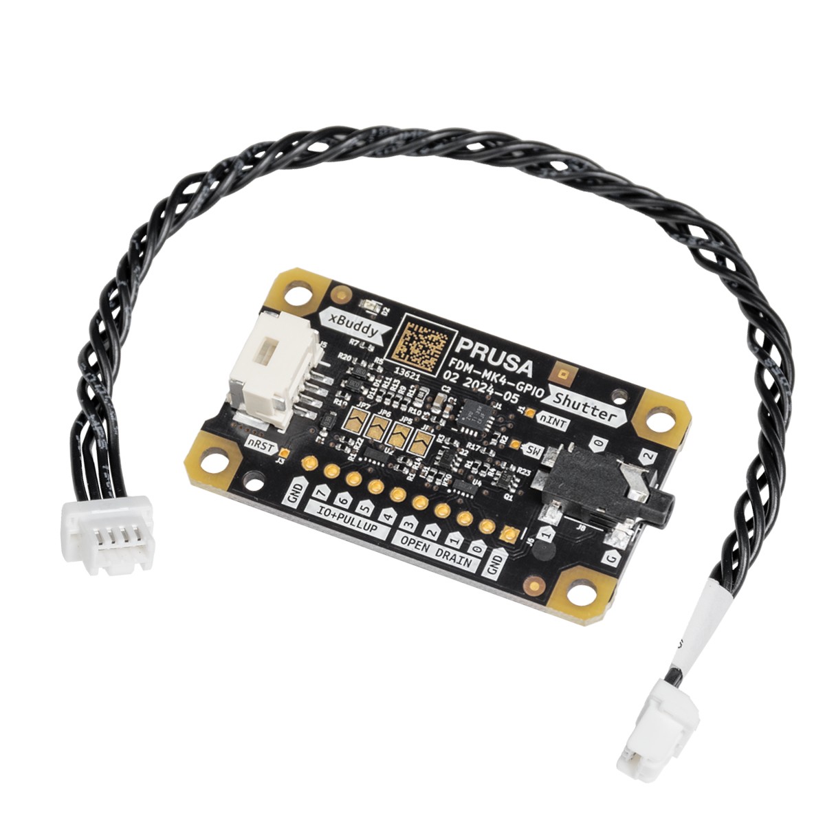
                  The GPIO module (General Purpose Input Output) is an additional, optional PCB that can be connected to the Prusa CORE One/+, and to the Original Prusa MK4/S, MK3.9/S, or MK3.5/S.

                  IMPORTANT: To utilize the full potential of the GPIO board you need firmware 6.2.0-alpha1 or newer. Visit the GitHub to download the latest firmware. 

                  The module provides expanded functionality by allowing the control of external devices through connections to the GPIO board pins, which can operate in either INPUT or OUTPUT mode. This versatility opens up a wide range of potential use cases.

                  Share and discuss your projects with the other members of the Prusa Community on our official forum. We have created a dedicated GPIO section.
                  Use-case ideas

                  The module can control a camera shutter at a precise moment, making it ideal for creating visually perfect time-lapses, where each picture is captured at the exact same point in time.

                  Beyond controlling a camera shutter, the module can be used for various other applications. For example, it can trigger external lighting to illuminate the print area at specific stages of the printing process, ensuring optimal lighting conditions for quality checks or photography. Additionally, it can be configured to activate cooling fans or other peripheral devices, such as extractors or alarms, based on custom G-Code execution during prints, helping maintain optimal operating conditions and improving the safety and efficiency of the 3D printing environment.

                  Another powerful use case is the integration of a macro keyboard, where each keypress can trigger the execution of specific G-Code commands. This setup allows for rapid manual control of the printer's functions, such as starting or pausing a print, adjusting temperatures, or moving the print head to an exact position. The ability to trigger custom actions with a simple keypress can significantly streamline workflows, making the GPIO expansion module a versatile and indispensable tool for those looking to fully customize and optimize their 3D printing setup.

                  Safety first! 

                  While the ability to trigger G-Code via GPIO inputs adds great flexibility, it also comes with limitations and potential risks. Improper use or poorly timed G-Code commands can interfere with the printing process, leading to print failures or even damage to the printer. It’s crucial to thoroughly test any custom G-Code setups in a controlled environment before deploying them in actual print jobs to avoid unintended consequences.

                  Additionally, we recommend that only experienced users with a solid understanding of electronics and G-Code manipulation utilize this GPIO module, as improper connections or configurations can result in hardware damage or safety hazards.

                  Schematics 

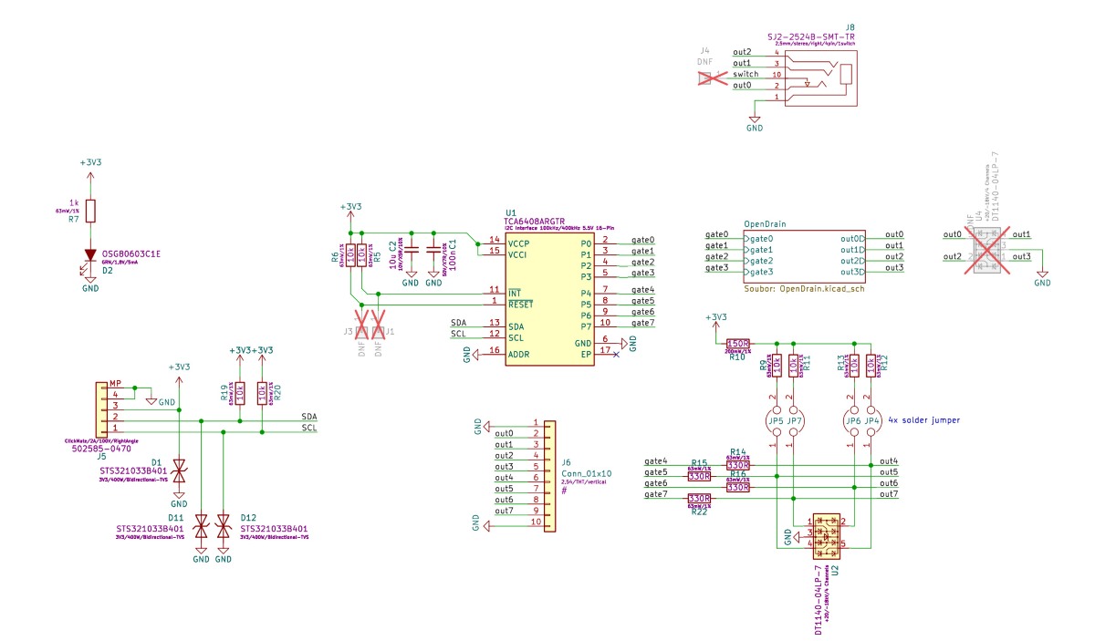
                  The schematics are open source, and available on our page Open Source at Prusa Research. 
                  How to install the GPIO board

                  1. Ensure the printer is cooled down to room temperature, and switch it off.
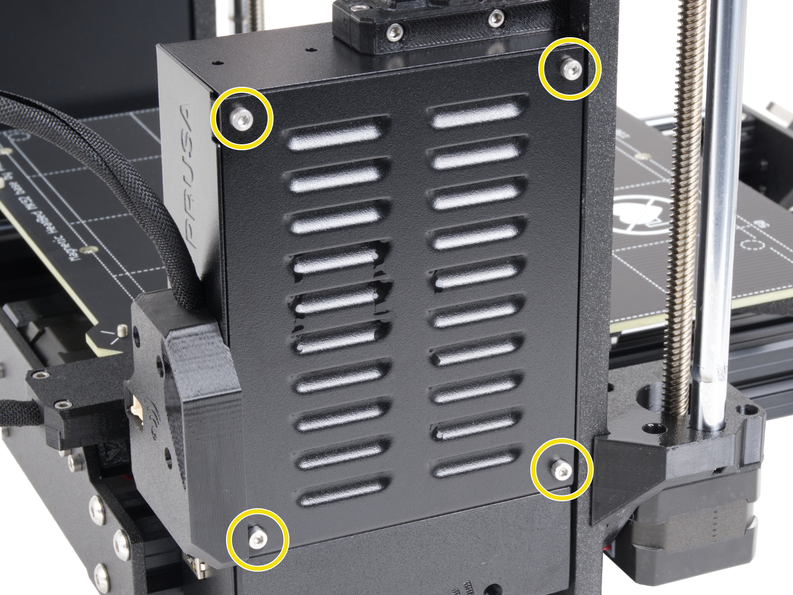
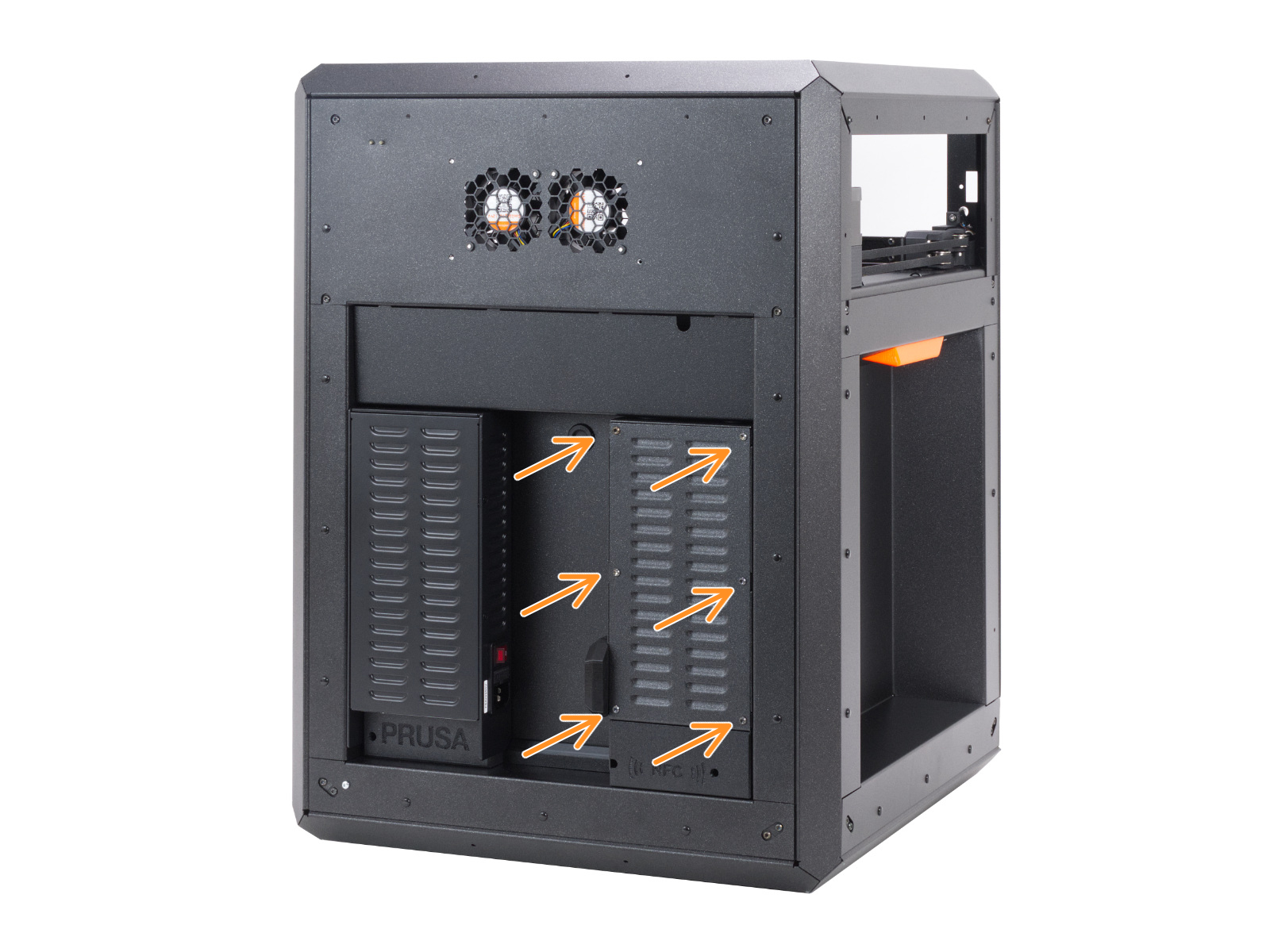
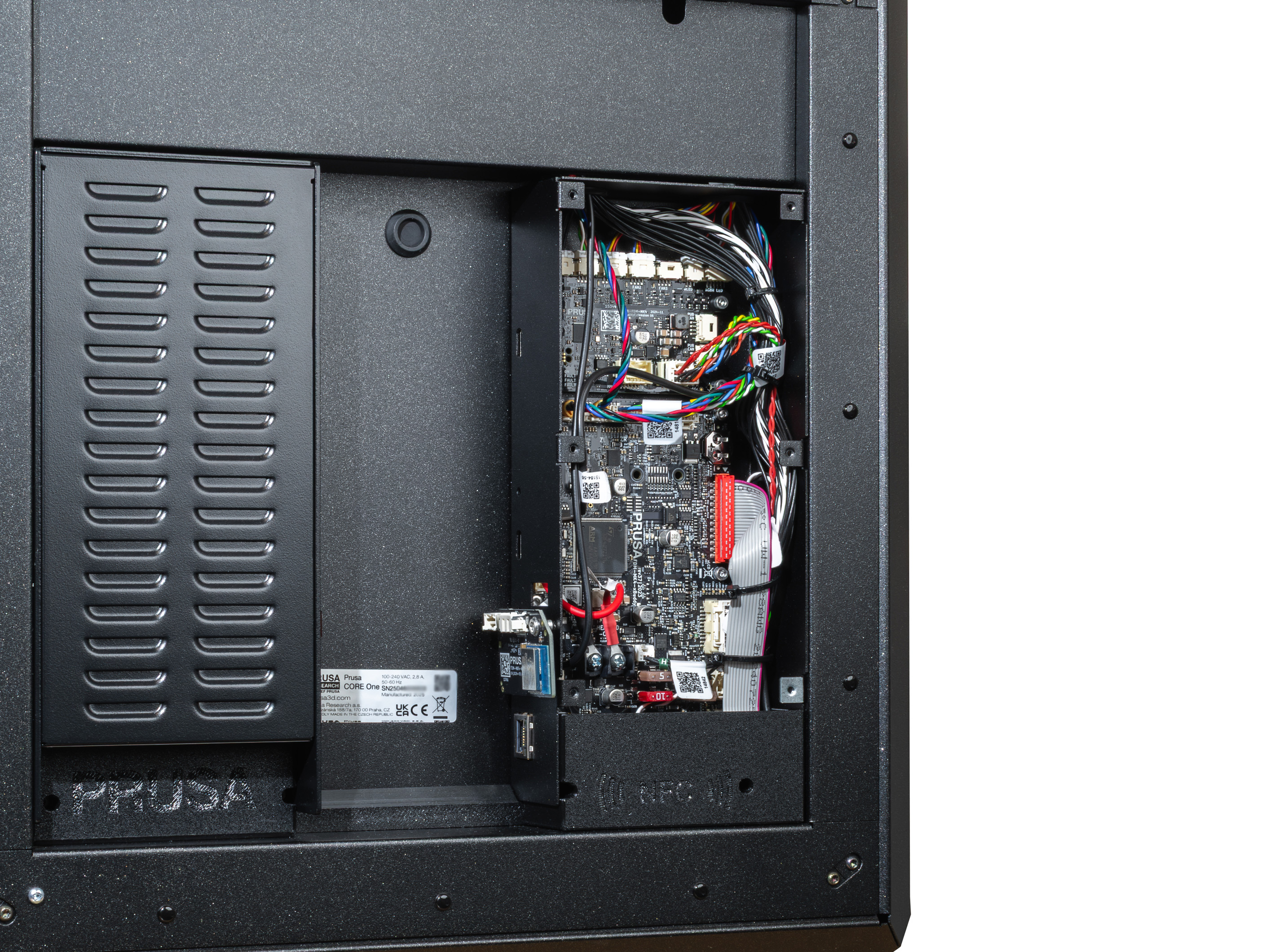
                  2. Open the xBuddy box cover by removing four M3x6 screws (MK-series), by removing six M3x4bT bolts (CORE One). 
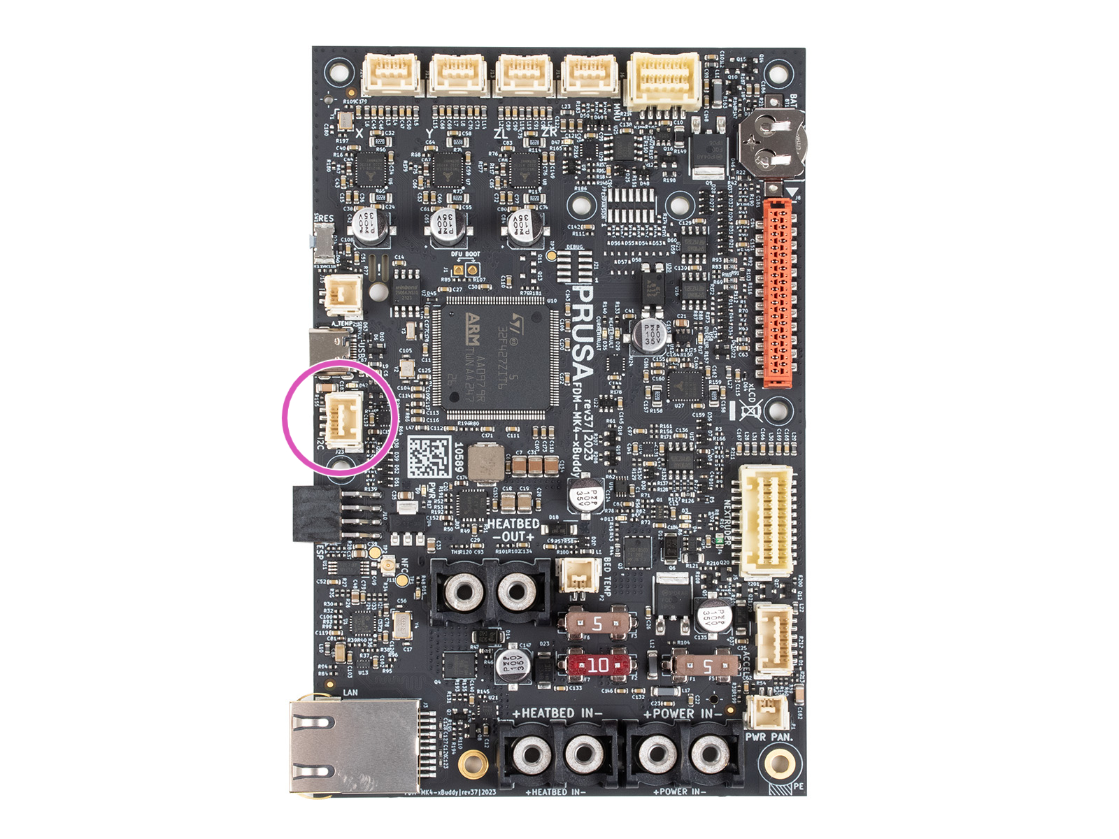
                  3. Connect the GPIO cable to the I2C port.
                  4. Close the xBuddy box cover.
                  5. Ensure that the GPIO does not touch any metal parts of the xBuddy box or its cover. 
                  6. Enjoy your project!

                  Pins

                  Limits - output mode

                  PIN 0 to 3 -> switch max. 24V, 500mA (to ground)
                  PIN 4 to 7 -> switch 0V or max. 3.3V, 10mA

                  Limits - input mode

                  PIN 4 to 7 -> 0V or 3.3V (max short-circuit current: 0.5mA with < 4 kΩ resistance).

                  Description

                  The board features 8 pins, numbered 0-7. Pins 0-3 can be used as output, and pins 4-7 can function as either input or output. Each pin is of the open-drain type when used as an output, meaning it is controlled by a transistor that connects the pin to the ground (0 V) when active. When the pin is inactive, it remains "floating", which means it is not connected to any specific voltage, but due to internal pull-up resistors, the voltage on the pin can hover around 3.3 V. 

                  It is possible to solder external pull-up resistors to the JP pins. This changes the behavior described above. For more details on that, see the pull-up resistors paragraph below. 

                  The behavior of the pins in an open-drain state when used as outputs can be explained as follows:

                  • Pin set to 0 (LOW): The pin is turned off and is in a "floating" state, which means it is not connected to any specific voltage. In this state, the voltage on the pin can fluctuate and is not well-defined unless stabilized by a pull-up resistor.

                  This "floating" state may cause the pin to pick up random electrical noise or interference, leading to unintended behavior if not properly managed. 

                  • Pin set to 1 (HIGH): The pin is turned on and connected to the ground (0 V), causing the voltage on the pin to drop to 0 V. This state is clear and does not lead to any ambiguity in signal detection.

                  When the pins are used as inputs, they can detect the voltage level applied to them. The input state is influenced by the presence of pull-up resistors, which can help ensure a consistently high voltage (3.3 V) when no other voltage source is applied.

                  Pull-up resistors

                  The board allows the connection of external pull-up resistors via solder jumpers labeled JP4 to JP7. These solder jumpers are located in the center of the board and are connected to the corresponding pins:

                  • JP4 is connected to Pin 4
                  • JP5 is connected to Pin 5
                  • JP6 is connected to Pin 6
                  • JP7 is connected to Pin 7

                  Solder jumpers JP7 to JP4 can be used to connect integrated pull-up resistors, which ensures that the pins remain at a high voltage (3.3 V) when not actively driven low by an external source or by the pin's output state. These pull-up resistors have a value of 10K ohms, which is a standard value to provide stable voltage without excessive current draw.

                  If the jumper is not soldered, the pin may remain in a floating state, potentially leading to unstable behavior. JP stands for "jumper": if the jumper is not soldered, the stabilizing 10 kOhms resistor is not connected to the gate and its signal. 

                  For less experienced users, it's important to understand that open-drain outputs do not inherently produce a high voltage (3.3 V) but rather allow a connection to ground (0 V). Pull-up resistors are necessary to ensure that the pin remains at a high voltage when turned off or when used as an input. If not properly managed, a "floating" voltage can cause the pin to pick up electrical noise, leading to unwanted switching or system instability.

                  Understanding pin values

                  To use advanced registers or read multiple pins at once, the board uses a binary-to-decimal system. Each pin has a unique numerical "weight." To target multiple pins, add their weights together.

                  Pin01234567
                  Weight1248163264128
                  • Example: if you want to use Pin 0 and Pin 1, the value is 1 + 2 = 3
                  • Example: to set all pins (0-7) at once, the value is 255

                  Setting GPIO via Custom G-Code

                  General Information

                  The following is a sequence of custom G-Code commands used for controlling the GPIO board. This allows you to configure output states, read input states, and manage other advanced settings on the board through G-Code instructions, integrating them seamlessly with your 3D printer’s workflow.

                  Pin control via G-Code

                  To control the output pins on the GPIO board, you can use the following G-Code commands:

                  1. Set Pin Mode (Output or Input)
                    • P<0-7>: Select the pin number to configure (from 0 to 7).
                    • B<0 or 1>: Set the pin mode.
                      • 0 - configures the pin as an output
                      • 1 - configures it as an input.
                    • Example: M262 P0 B0 - Configures pin 0 as an output pin.
                       
                  2. Write state to an Output Pin
                    • P<0-7>: Select the pin number to write to (from 0 to 7).
                    • B<0 or 1>: Write 0 to set the pin to LOW (0 V) or 1 to set the pin to HIGH (3.3 V).
                    • Example: M264 P0 B1 - Sets output pin 0 to HIGH (1).
                       
                  3. Toggle state of Output Pin
                    • P<0-7>: Select the pin number to toggle (from 0 to 7).
                    • This command flips the current state of the selected pin.
                    • Example: M265 P0 - Toggles pin 0.
                       When using M267, the R parameter selects the "folder," and the B parameter provides the pin map:
                  4. Advanced Register Setup (For Experienced Users)

                  When using M267, the R parameter selects the "folder," and the B parameter provides the pin map:

                    • R<1-3>: Select the register to configure:
                      • 1: Output Register. Sets the voltage for output pins. 0 = Low (0V), 1 = High (3.3V).
                      • 2: Polarity Register. Defines logic. 0 = Normal, 1 = Inverted. Useful for preventing "ghost" triggers on pins 0-3.
                      • 3: Configuration Register. Defines direction. 0 = Output, 1 = Input. (e.g., B255 makes all pins inputs).
                    • B<0-255>: Set the value to be written to the selected register.
                    • Example: M267 R3 B255 - Configures the Configuration Register with the value 255 (all pins set to inputs).

                  To read the state of pins or set up configurations, use the following G-Code commands:

                  1. Read state of Pin
                    • P<0-7>: Select the pin number to read from (from 0 to 7).
                    • The returned value will indicate whether the pin is HIGH (1) or LOW (0).
                    • Example: M263 P6 - Reads the state of pin 6 (returns 32 for HIGH or 0 for LOW).
                       
                  2. Read Entire Input Register
                    • This command reads the entire input register, returning a number in given "style" format that represents the states of all input pins (from 0 to 7).
                    • Possible states are:
                      • 1 - HEX DUMP
                      • 2 - signed two byte integer, base 10 (int16)
                      • 3 - unsigned byte, base 10 (uint8)
                    • device address is always 32
                    • Example: M261 A32 B1 S3 - reads the entire input register and returns it as unsigned byte base 10
                       
                  3. Read IO expander's register (For Experienced Users)
                    • this reads the whole byte of the given register at once
                    • R<0-3>:
                      • 0 - Input
                      • 1 - Output
                      • 2 - Polarity
                      • 3 - Config
                    • Example: M268 R3 - Reads Config register

                  Interpreting Read Results

                  When you read a register (M268) or the entire input (M261), the printer returns a single number. Use the weight table to decode it. 

                  Note on M261: This command is for communicating with external I2C "Slave" devices connected to the board. Address 32 is the GPIO board itself; other addresses depend on the specific hardware you attach.
                  Pin01234567
                  Weight1248163264128

                  Examples

                  • If M268 R0 returns 64, Pin 6 is active.
                  • If it returns 192, then both Pin 6 (64) and Pin 7 (128) are active (64+128=192).

                  How to Set Up G-code for Input Pins

                  To configure input pins for your setup, each input pin is automatically mapped to a specific G-code file located on the USB drive. These files must be stored in a folder named "macros" and follow a strict naming convention: the file name must be in the format

                  where {pin_number} corresponds to the specific GPIO pin you are using. All letters in the file names must be lowercase.

                  For example:

                  • if you are using pin 7, the corresponding G-code file must be named btn_7.gcode and placed in the "macros" folder.
                  • similarly, for pin 4, the file should be named btn_4.gcode

                  The system supports 8 input pins on the GPIO board, and each pin can be mapped to a unique G-code file in this way.

                  When a G-code file is triggered via its corresponding input pin, the G-code stored in that file is immediately injected into the ongoing process. Please note that there is a size limit for each G-code file, which must not exceed 1024 bytes.

                  While the naming convention (btn_x.gcode) is fixed, the content of the file is limited only by the Prusa firmware.

                  You can inject any valid G-code. This includes M600 (filament change), M112 (emergency stop), M104 (temperature changes), or G28 (homing).
                  Limitations: Macros are injected into the current command stream. The system does not currently support software-based triggers (e.g., "run macro when print finishes"); triggers are strictly physical via the input pins.

                  Advanced Input Control and Macro Triggering

                  When an input pin is configured using M262 and set to 1 (input mode), the state of the pin is periodically checked every 0.5 seconds.

                  If a button connected to the pin is pressed (pin state goes LOW), it triggers a macro button. For example, a button on pin 7 can automatically execute a macro stored in the file macros/btn_7.gcode on a USB drive. The macro is injected into the print sequence, with a size limit of 1024 bytes.

                  Persistent Memory

                  Configuration of the pins and their states are stored in EEPROM, ensuring that pin settings (output/input modes, polarity, and states) are preserved even after a power cycle.
                  Changes made via M262, M264, M267, or any other relevant G-Code will update the EEPROM, so the settings are persistent.

                  Edge Cases

                  For pins 0-3, which lack internal pull-up resistors, configuring them as input without additional external circuitry may result in an inverted logic state. This can inadvertently trigger macro execution due to their default idle state being LOW (0).

                  You can invert the logic of input pins using the Polarity Register (M267 R2 B<value>). This feature is particularly useful for pins that do not have pull-up resistors (pins 0-3), which default to an idle state of 0 (LOW) and might trigger unwanted actions when left unconfigured.

                  All pins (0-7) support polarity inversion equally. This means you can invert the logic for any pin, which is configured as input.

                  The primary difference in behavior between the pins comes from the fact that pins 4-7 can utilize internal pull-up resistors, which hold them at a HIGH state (3.3 V) when not actively driven LOW. However, these pull-up resistors are only active if the corresponding solder jumpers (JP4 to JP7) are connected. If these jumpers are not soldered, pins 4-7 behave similarly to pins 0-3, defaulting to a floating state.

                  When using input pins to trigger macros, the system is designed to detect a LOW state as indicating a pressed button. For pins without active pull-up resistors, this default LOW state can inadvertently trigger macros unless polarity inversion is used.

                  Warnings and Limitations

                  When configuring or writing to pins, the system outputs a warning via the serial port if there is a mismatch between the intended operation (e.g., trying to write to an input pin). It is essential to correctly configure pins using M262 to avoid such conflicts.

                  Custom G-Code in Prusa Slicer

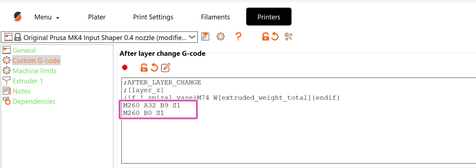
                  Insert the code in the exact spots where it is needed, after/before another particular G-Code command. In the example screenshot, the custom G-Code that controls the GPIO board is set through PrusaSlicer and is positioned after each layer change. However, it can be positioned at any point. 
                  Examples

                  Sample Connection of GPIO Module to Addon Controller (Fan Filter and LED)

                  In the image attached below, we can see the connection between the GPIO module and the addon controller responsible for controlling the Original Prusa Enclosure's fan filter and LED. 
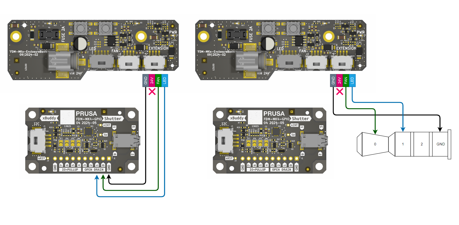
                  We are currently developing a jack-to-molex cable solution for connection between the GPIO board and the EnclosureBasic board. This will provide an easy and user-friendly way to manage the enclosure’s controls.

                  Image of example setup for enclosure

                  Connecting the GPIO board to the Addon Controller allows the printer to automate enclosure features. Example: 

                  Direction: Set the connecting pin (e.g., Pin 0) to output: M262 P0 B0.
                  Automation: In PrusaSlicer, go to Printer Settings > Custom G-code.

                  Start G-code: Add M264 P0 B1 to turn on the enclosure lights/fan when the print begins.
                  End G-code: Add M264 P0 B0 to turn them off when finished.

                  この記事は役に立ちましたか?
                  この操作は登録ユーザーのみが利用できます。ログインしてください。
                  ログイン してコメントを投稿する
                  コメントなし

                  トピックス

                  • あなたのプリンターについて
                    • プリンターの機能
                      • スチールシートプロファイル
                      • 柔軟性のあるスチールシート(ガイドポスト)
                      • パワーモード
                      • IR フィラメントセンサー (MK2.5S, MK3S/+, MK3.5/S))
                      • 実験的なメニュー (MK4/S, MK3.9/S, MK3.5/S, XL, MINI/+)
                      • ロードセル (MK4/S, MK3.9, XL)
                      • ステータスLEDについて (MK4/XL)
                      • Nextruder フィラメントセンサー (CORE One, MK4/S, MK3.9/S, XL)
                      • Buddy firmware-specific G-code commands
                      • Nextruder silicone sock (CORE One/+, CORE One L/+, XL/+, MK4/S, MK3.9/S)
                      • Model preview
                      • オブエジェクトのキャンセル (MK4, MK3.9, XL, MINI/+)
                      • タッチスクリーン機能 (CORE One, MK4/S, MK3.9/S, MK3.5/S, XL)
                      • NFC antenna
                      • Accelerometer (CORE One, MK4/S, MK3.9/S)
                      • GPIO Module
                      • Network Connection (CORE One L, CORE One, MK4S, MK3.9S)
                      • MMU3における PrusaノズルとCHTノズル
                      • Flashing custom firmware (CORE One L, CORE One, MK4/S, MK3.9/S, MK3.5/S)
                      • Safety and safety timer messages (CORE One, CORE One L, XL, MK4/S, MK3.9/S, MK3.5/S)
                      • Advanced filtration system for Prusa CORE One
                      • Prusa CORE One から CORE One+ へのアップグレード(コミュニティ版)
                    • プリンターの説明
                    • 一般情報