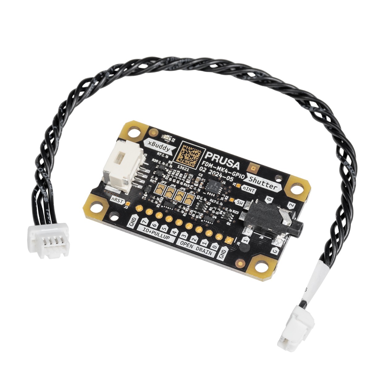
The GPIO module (General Purpose Input Output) is an additional, optional PCB that can be connected to the Prusa CORE One/+, and to the Original Prusa MK4/S, MK3.9/S, or MK3.5/S.
The module provides expanded functionality by allowing the control of external devices through connections to the GPIO board pins, which can operate in either INPUT or OUTPUT mode. This versatility opens up a wide range of potential use cases.
Share and discuss your projects with the other members of the Prusa Community on our official forum. We have created a dedicated GPIO section.
Use-case ideas
The module can control a camera shutter at a precise moment, making it ideal for creating visually perfect time-lapses, where each picture is captured at the exact same point in time.
Beyond controlling a camera shutter, the module can be used for various other applications. For example, it can trigger external lighting to illuminate the print area at specific stages of the printing process, ensuring optimal lighting conditions for quality checks or photography. Additionally, it can be configured to activate cooling fans or other peripheral devices, such as extractors or alarms, based on custom G-Code execution during prints, helping maintain optimal operating conditions and improving the safety and efficiency of the 3D printing environment.
Another powerful use case is the integration of a macro keyboard, where each keypress can trigger the execution of specific G-Code commands. This setup allows for rapid manual control of the printer's functions, such as starting or pausing a print, adjusting temperatures, or moving the print head to an exact position. The ability to trigger custom actions with a simple keypress can significantly streamline workflows, making the GPIO expansion module a versatile and indispensable tool for those looking to fully customize and optimize their 3D printing setup.
Safety first!
While the ability to trigger G-Code via GPIO inputs adds great flexibility, it also comes with limitations and potential risks. Improper use or poorly timed G-Code commands can interfere with the printing process, leading to print failures or even damage to the printer. It’s crucial to thoroughly test any custom G-Code setups in a controlled environment before deploying them in actual print jobs to avoid unintended consequences.
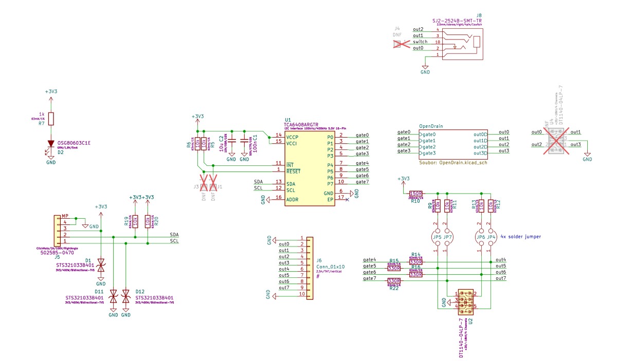
Schematics
The schematics are open source, and available on our page Open Source at Prusa Research.
How to install the GPIO board
- Ensure the printer is cooled down to room temperature, and switch it off.
- Open the xBuddy box cover by removing four M3x6 screws (MK-series), by removing six M3x4bT bolts (CORE One).
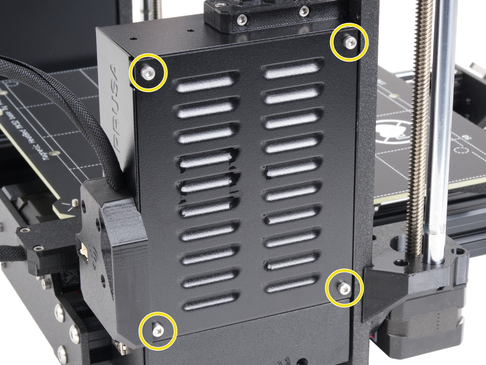
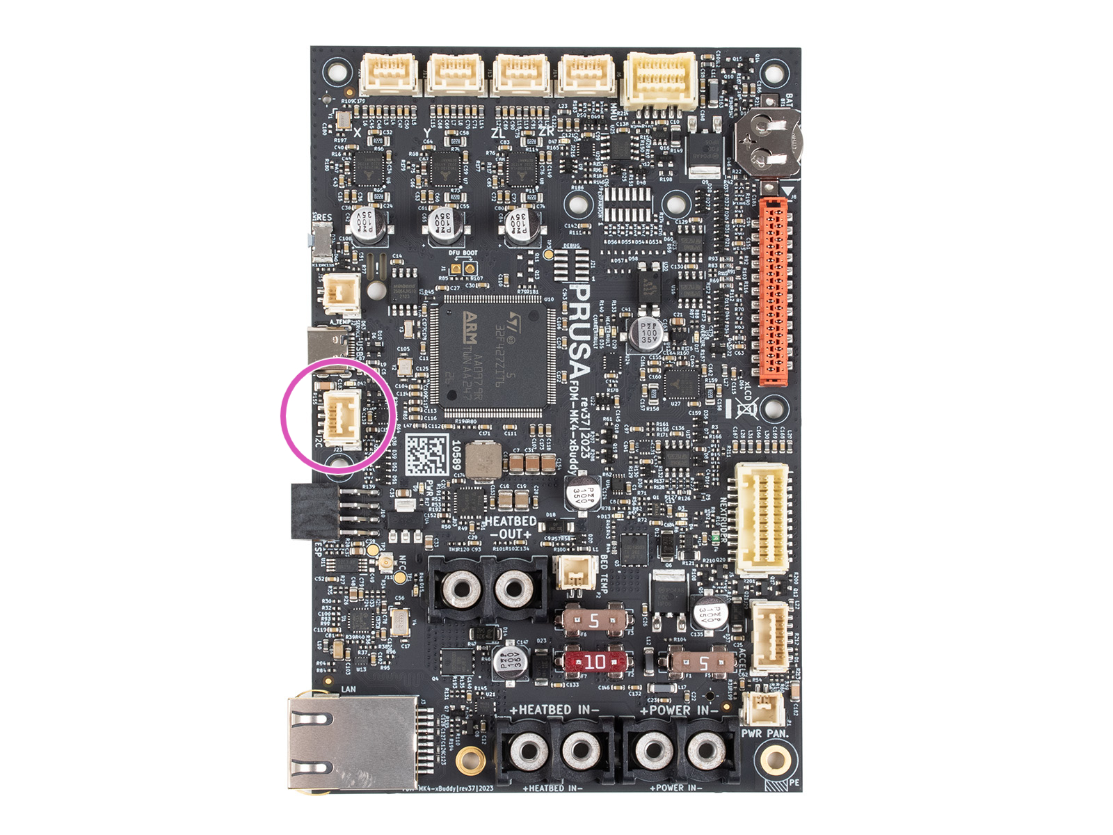
- Connect the GPIO cable to the I2C port.
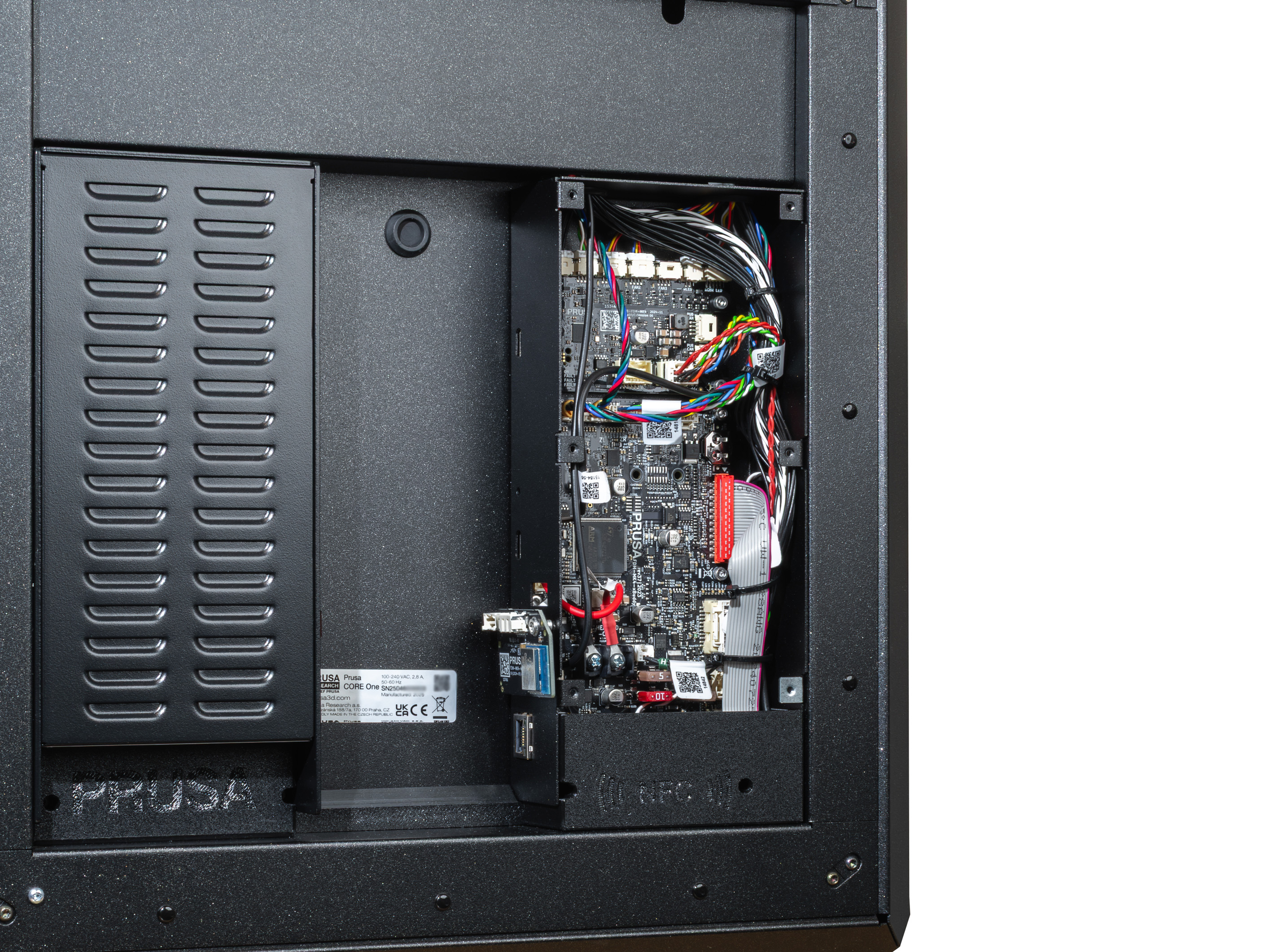
- Close the xBuddy box cover.
- Ensure that the GPIO does not touch any metal parts of the xBuddy box or its cover.
- Enjoy your project!
Pins
Limits - output mode
PIN 0 to 3 -> switch max. 24V, 500mA (to ground)
PIN 4 to 7 -> switch 0V or max. 3.3V, 10mA
Limits - input mode
PIN 4 to 7 -> 0V or 3.3V (max short-circuit current: 0.5mA with < 4 kΩ resistance).
Description
The board features 8 pins, numbered 0-7. Pins 0-3 can be used as output, and pins 4-7 can function as either input or output. Each pin is of the open-drain type when used as an output, meaning it is controlled by a transistor that connects the pin to the ground (0 V) when active. When the pin is inactive, it remains "floating", which means it is not connected to any specific voltage, but due to internal pull-up resistors, the voltage on the pin can hover around 3.3 V.
The behavior of the pins in an open-drain state when used as outputs can be explained as follows:
- Pin set to 0 (LOW): The pin is turned off and is in a "floating" state, which means it is not connected to any specific voltage. In this state, the voltage on the pin can fluctuate and is not well-defined unless stabilized by a pull-up resistor.
This "floating" state may cause the pin to pick up random electrical noise or interference, leading to unintended behavior if not properly managed.
- Pin set to 1 (HIGH): The pin is turned on and connected to the ground (0 V), causing the voltage on the pin to drop to 0 V. This state is clear and does not lead to any ambiguity in signal detection.
When the pins are used as inputs, they can detect the voltage level applied to them. The input state is influenced by the presence of pull-up resistors, which can help ensure a consistently high voltage (3.3 V) when no other voltage source is applied.
Pull-up resistors
The board allows the connection of external pull-up resistors via solder jumpers labeled JP4 to JP7. These solder jumpers are located in the center of the board and are connected to the corresponding pins:
- JP4 is connected to Pin 4
- JP5 is connected to Pin 5
- JP6 is connected to Pin 6
- JP7 is connected to Pin 7
Solder jumpers JP7 to JP4 can be used to connect integrated pull-up resistors, which ensures that the pins remain at a high voltage (3.3 V) when not actively driven low by an external source or by the pin's output state. These pull-up resistors have a value of 10K ohms, which is a standard value to provide stable voltage without excessive current draw.
If the jumper is not soldered, the pin may remain in a floating state, potentially leading to unstable behavior. JP stands for "jumper": if the jumper is not soldered, the stabilizing 10 kOhms resistor is not connected to the gate and its signal.
For less experienced users, it's important to understand that open-drain outputs do not inherently produce a high voltage (3.3 V) but rather allow a connection to ground (0 V). Pull-up resistors are necessary to ensure that the pin remains at a high voltage when turned off or when used as an input. If not properly managed, a "floating" voltage can cause the pin to pick up electrical noise, leading to unwanted switching or system instability.
Understanding pin values
To use advanced registers or read multiple pins at once, the board uses a binary-to-decimal system. Each pin has a unique numerical "weight." To target multiple pins, add their weights together.
| Pin | 0 | 1 | 2 | 3 | 4 | 5 | 6 | 7 |
| Weight | 1 | 2 | 4 | 8 | 16 | 32 | 64 | 128 |
- Example: if you want to use Pin 0 and Pin 1, the value is 1 + 2 = 3
- Example: to set all pins (0-7) at once, the value is 255
Setting GPIO via Custom G-Code
General Information
The following is a sequence of custom G-Code commands used for controlling the GPIO board. This allows you to configure output states, read input states, and manage other advanced settings on the board through G-Code instructions, integrating them seamlessly with your 3D printer’s workflow.
Pin control via G-Code
To control the output pins on the GPIO board, you can use the following G-Code commands:
- Set Pin Mode (Output or Input)
- P<0-7>: Select the pin number to configure (from 0 to 7).
- B<0 or 1>: Set the pin mode.
- 0 - configures the pin as an output
- 1 - configures it as an input.
- Example: M262 P0 B0 - Configures pin 0 as an output pin.
- Write state to an Output Pin
- P<0-7>: Select the pin number to write to (from 0 to 7).
- B<0 or 1>: Write 0 to set the pin to LOW (0 V) or 1 to set the pin to HIGH (3.3 V).
- Example: M264 P0 B1 - Sets output pin 0 to HIGH (1).
- Toggle state of Output Pin
- P<0-7>: Select the pin number to toggle (from 0 to 7).
- This command flips the current state of the selected pin.
- Example: M265 P0 - Toggles pin 0.
When using M267, the R parameter selects the "folder," and the B parameter provides the pin map:
- Advanced Register Setup (For Experienced Users)
When using M267, the R parameter selects the "folder," and the B parameter provides the pin map:
-
- R<1-3>: Select the register to configure:
- 1: Output Register. Sets the voltage for output pins. 0 = Low (0V), 1 = High (3.3V).
- 2: Polarity Register. Defines logic. 0 = Normal, 1 = Inverted. Useful for preventing "ghost" triggers on pins 0-3.
- 3: Configuration Register. Defines direction. 0 = Output, 1 = Input. (e.g., B255 makes all pins inputs).
- B<0-255>: Set the value to be written to the selected register.
- Example: M267 R3 B255 - Configures the Configuration Register with the value 255 (all pins set to inputs).
- R<1-3>: Select the register to configure:
To read the state of pins or set up configurations, use the following G-Code commands:
- Read state of Pin
- P<0-7>: Select the pin number to read from (from 0 to 7).
- The returned value will indicate whether the pin is HIGH (1) or LOW (0).
- Example: M263 P6 - Reads the state of pin 6 (returns 32 for HIGH or 0 for LOW).
- Read Entire Input Register
- This command reads the entire input register, returning a number in given "style" format that represents the states of all input pins (from 0 to 7).
- Possible states are:
- 1 - HEX DUMP
- 2 - signed two byte integer, base 10 (int16)
- 3 - unsigned byte, base 10 (uint8)
- device address is always 32
- Example: M261 A32 B1 S3 - reads the entire input register and returns it as unsigned byte base 10
- Read IO expander's register (For Experienced Users)
- this reads the whole byte of the given register at once
- R<0-3>:
- 0 - Input
- 1 - Output
- 2 - Polarity
- 3 - Config
- Example: M268 R3 - Reads Config register
Interpreting Read Results
When you read a register (M268) or the entire input (M261), the printer returns a single number. Use the weight table to decode it.
| Pin | 0 | 1 | 2 | 3 | 4 | 5 | 6 | 7 |
| Weight | 1 | 2 | 4 | 8 | 16 | 32 | 64 | 128 |
Examples
- If M268 R0 returns 64, Pin 6 is active.
- If it returns 192, then both Pin 6 (64) and Pin 7 (128) are active (64+128=192).
How to Set Up G-code for Input Pins
To configure input pins for your setup, each input pin is automatically mapped to a specific G-code file located on the USB drive. These files must be stored in a folder named "macros" and follow a strict naming convention: the file name must be in the format
where {pin_number} corresponds to the specific GPIO pin you are using. All letters in the file names must be lowercase.
For example:
- if you are using pin 7, the corresponding G-code file must be named btn_7.gcode and placed in the "macros" folder.
- similarly, for pin 4, the file should be named btn_4.gcode
The system supports 8 input pins on the GPIO board, and each pin can be mapped to a unique G-code file in this way.
When a G-code file is triggered via its corresponding input pin, the G-code stored in that file is immediately injected into the ongoing process. Please note that there is a size limit for each G-code file, which must not exceed 1024 bytes.
While the naming convention (btn_x.gcode) is fixed, the content of the file is limited only by the Prusa firmware.
You can inject any valid G-code. This includes M600 (filament change), M112 (emergency stop), M104 (temperature changes), or G28 (homing).
Limitations: Macros are injected into the current command stream. The system does not currently support software-based triggers (e.g., "run macro when print finishes"); triggers are strictly physical via the input pins.
Advanced Input Control and Macro Triggering
When an input pin is configured using M262 and set to 1 (input mode), the state of the pin is periodically checked every 0.5 seconds.
If a button connected to the pin is pressed (pin state goes LOW), it triggers a macro button. For example, a button on pin 7 can automatically execute a macro stored in the file macros/btn_7.gcode on a USB drive. The macro is injected into the print sequence, with a size limit of 1024 bytes.
Persistent Memory
Configuration of the pins and their states are stored in EEPROM, ensuring that pin settings (output/input modes, polarity, and states) are preserved even after a power cycle.
Changes made via M262, M264, M267, or any other relevant G-Code will update the EEPROM, so the settings are persistent.
Edge Cases
For pins 0-3, which lack internal pull-up resistors, configuring them as input without additional external circuitry may result in an inverted logic state. This can inadvertently trigger macro execution due to their default idle state being LOW (0).
You can invert the logic of input pins using the Polarity Register (M267 R2 B<value>). This feature is particularly useful for pins that do not have pull-up resistors (pins 0-3), which default to an idle state of 0 (LOW) and might trigger unwanted actions when left unconfigured.
The primary difference in behavior between the pins comes from the fact that pins 4-7 can utilize internal pull-up resistors, which hold them at a HIGH state (3.3 V) when not actively driven LOW. However, these pull-up resistors are only active if the corresponding solder jumpers (JP4 to JP7) are connected. If these jumpers are not soldered, pins 4-7 behave similarly to pins 0-3, defaulting to a floating state.
When using input pins to trigger macros, the system is designed to detect a LOW state as indicating a pressed button. For pins without active pull-up resistors, this default LOW state can inadvertently trigger macros unless polarity inversion is used.
Warnings and Limitations
When configuring or writing to pins, the system outputs a warning via the serial port if there is a mismatch between the intended operation (e.g., trying to write to an input pin). It is essential to correctly configure pins using M262 to avoid such conflicts.
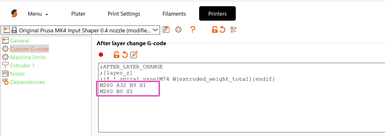
Custom G-Code in Prusa Slicer
Insert the code in the exact spots where it is needed, after/before another particular G-Code command. In the example screenshot, the custom G-Code that controls the GPIO board is set through PrusaSlicer and is positioned after each layer change. However, it can be positioned at any point.
Examples
Sample Connection of GPIO Module to Addon Controller (Fan Filter and LED)
In the image attached below, we can see the connection between the GPIO module and the addon controller responsible for controlling the Original Prusa Enclosure's fan filter and LED.
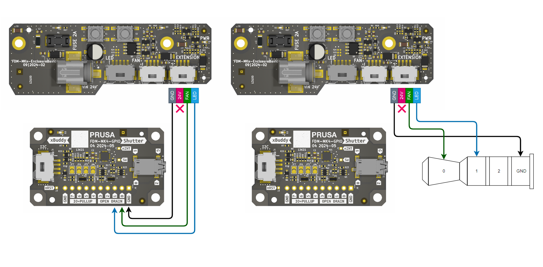
Connecting the GPIO board to the Addon Controller allows the printer to automate enclosure features. Example:
Direction: Set the connecting pin (e.g., Pin 0) to output: M262 P0 B0.
Automation: In PrusaSlicer, go to Printer Settings > Custom G-code.
Start G-code: Add M264 P0 B1 to turn on the enclosure lights/fan when the print begins.
End G-code: Add M264 P0 B0 to turn them off when finished.