After successfully finishing the build of your Original Prusa MMU2S upgrade and going through 8. Preflight check & Calibration of the assembly manual you should be good to go. However, if you are encountering persistant issues, we have compiled a checklist of what you want to double-check.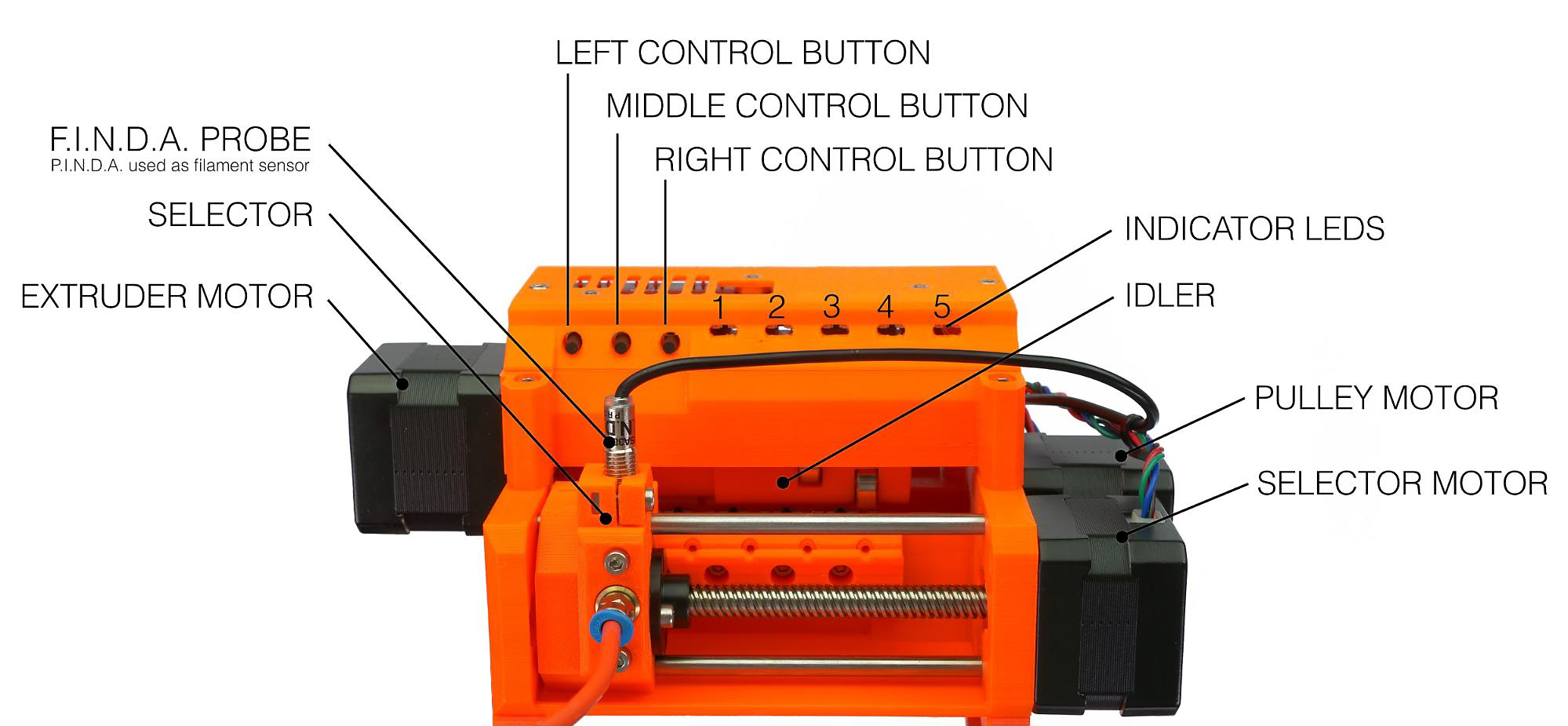
Necessary calibrations
With the hundreds of filament changes that can go into a single MMU print, the system needs to know where each filament is at all times. Therefore, there are two sensors, that both have to be set up properly. You can see if they trigger correctly on the LCD menu under Support -> Sensor info. Each should trigger "1" of filament is present and "0" when it's not.
IR filament sensor calibration
This is one of the two sensors on the MMU2S, located on the extruder of the printer. Before you start printing, make sure your IR filament sensor mechanism is properly calibrated.
SuperFINDA sensor calibration
The SuperFINDA is the second sensor on the MMU2S. Its position is crucial to ensure smooth operation. Its assembly can also collect debris or strings from filament changes. To set it up and inspect it, please see FINDA setup and troubleshooting.
Hardware configurations
Idler screws tension
Just like the extruder idler screw, its MMU2S counterparts need to be tightened just right. If the idler springs are over-tightened, it may cause the idler motor to skip. Over-tightening can also cause the pulleys to be "choked" by the filament.
To find the perfect tension, tighten the screw to about 0.5 mm (0.02 in) below the edge of the hole, on both sides of the idler body, and follow these steps:
- All 5 filaments have to be loaded to the hobbed pulley's position.
- Move the selector to the far right (5th filament position) and back, by long-pressing the right and left control buttons.
- If you hear clicking, loosen the screws a little bit and try to move the selector again.
- Repeat until there is no more clicking.
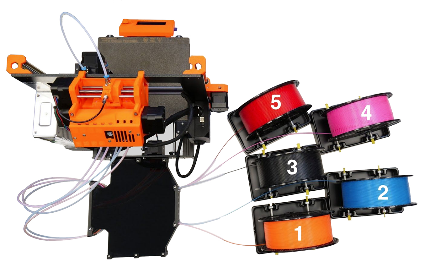
Spools and buffer positioning
The spool holders shouldn't be too close to each other. Ideally, the spools should be positioned as described and shown in the handbook (picture below).
Assembly inspection
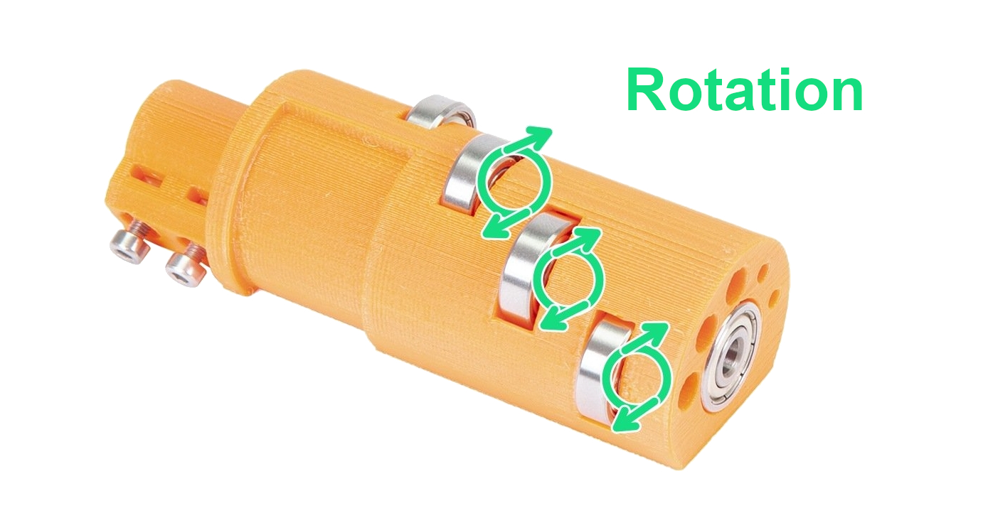
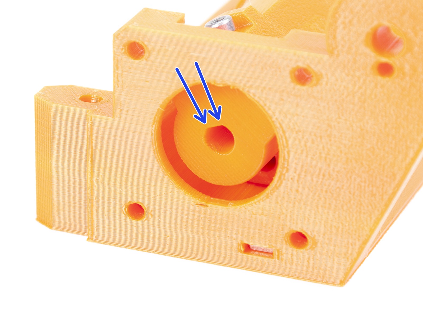
Idler Bearings
The five bearings that are protruding from the idler cylinder must be spinning freely on their shafts. If that is not the case, you can always remove and inspect the bearing by pushing out the shaft from the opposite side they are inserted. Use a rod or Allen key at least 100 mm (~4 in) long.
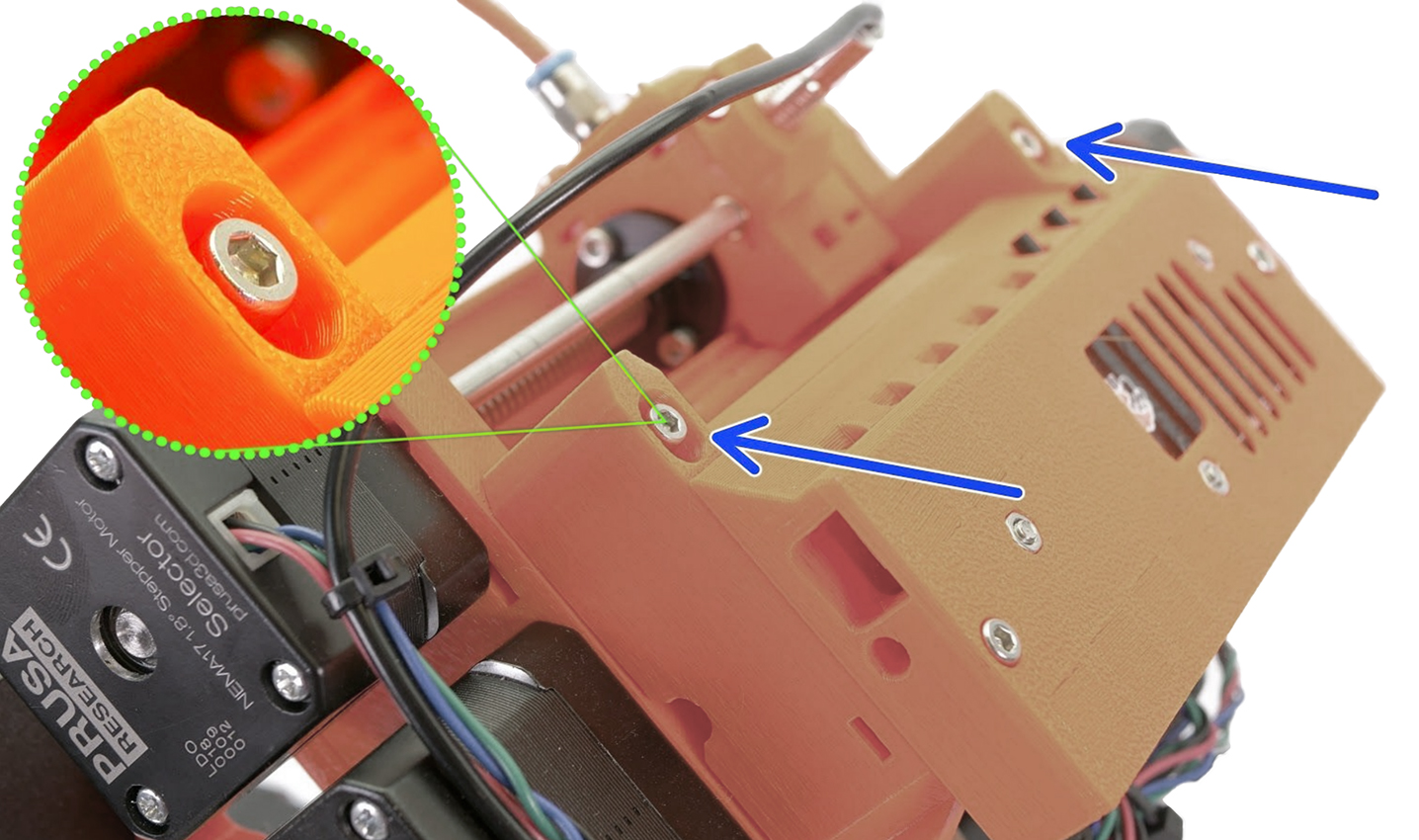
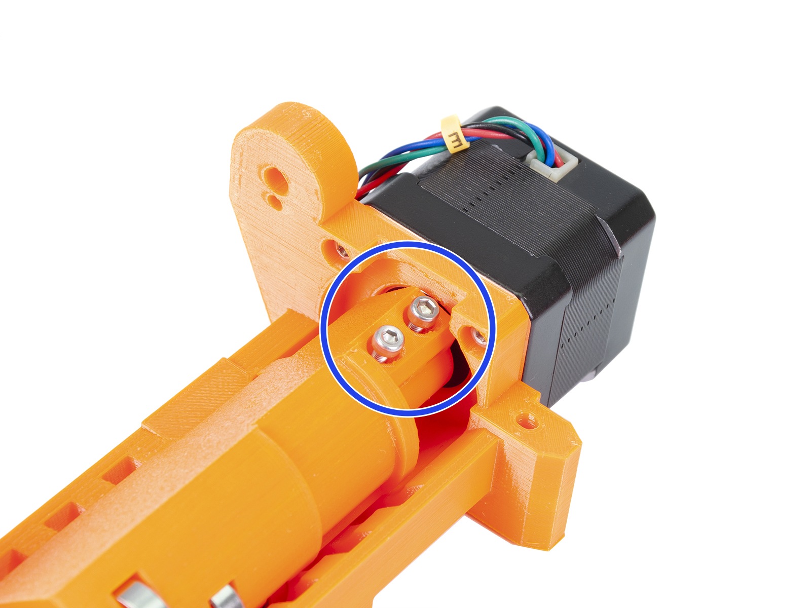
Securing the idler on the shaft
The idler cylinder has to be secured by two M3x10 screws which act as grub set screws on the MMU2S extruder motor shaft.
Keep in mind that these two M3x10 screws might also get loose over time, so check the tightening every few dozen print hours. Another potential issue for you to verify is whether the two screws are tightened against the flat part of the extruder motor shaft. See 4. Idler body assembly of the assembly manual.
 |  |
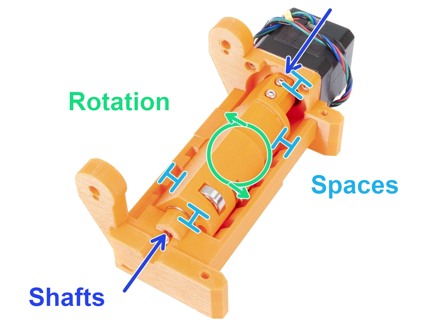
Idler rotation
The idler must have some space on the left or right side and around the circumference of the idler barrel (see the light blue spacers in the picture below). The solution is to move the idler barrel a little bit away from the idler body and extend the gap. Around 1 mm (0.04 in) gap on both sides is more than enough. Test by rotating the idler by hand when the printer is off.
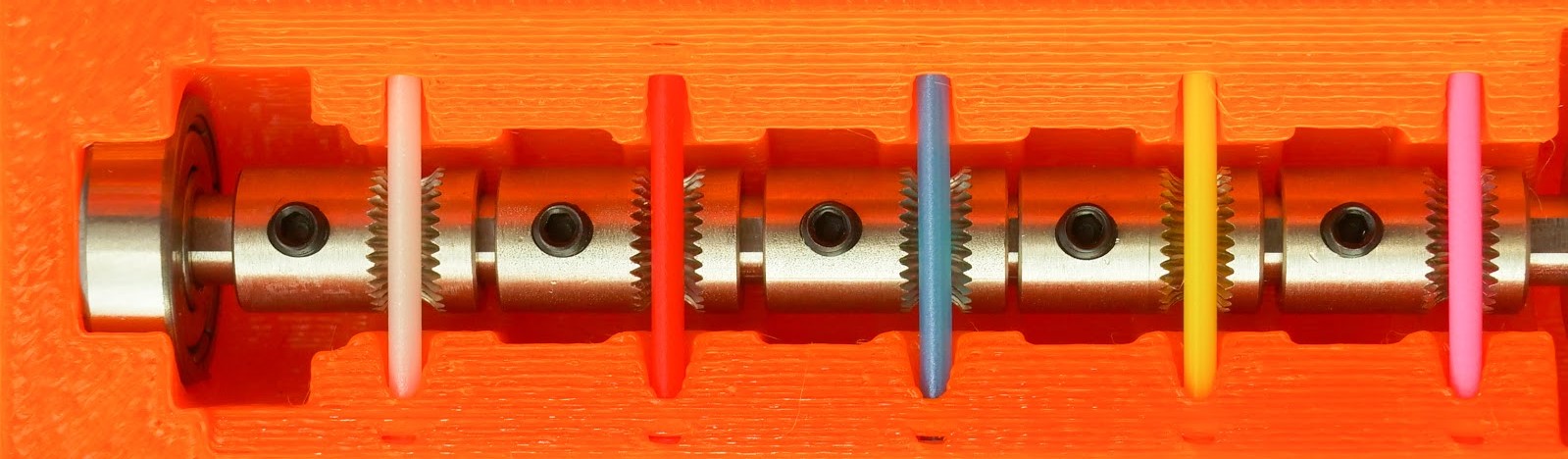
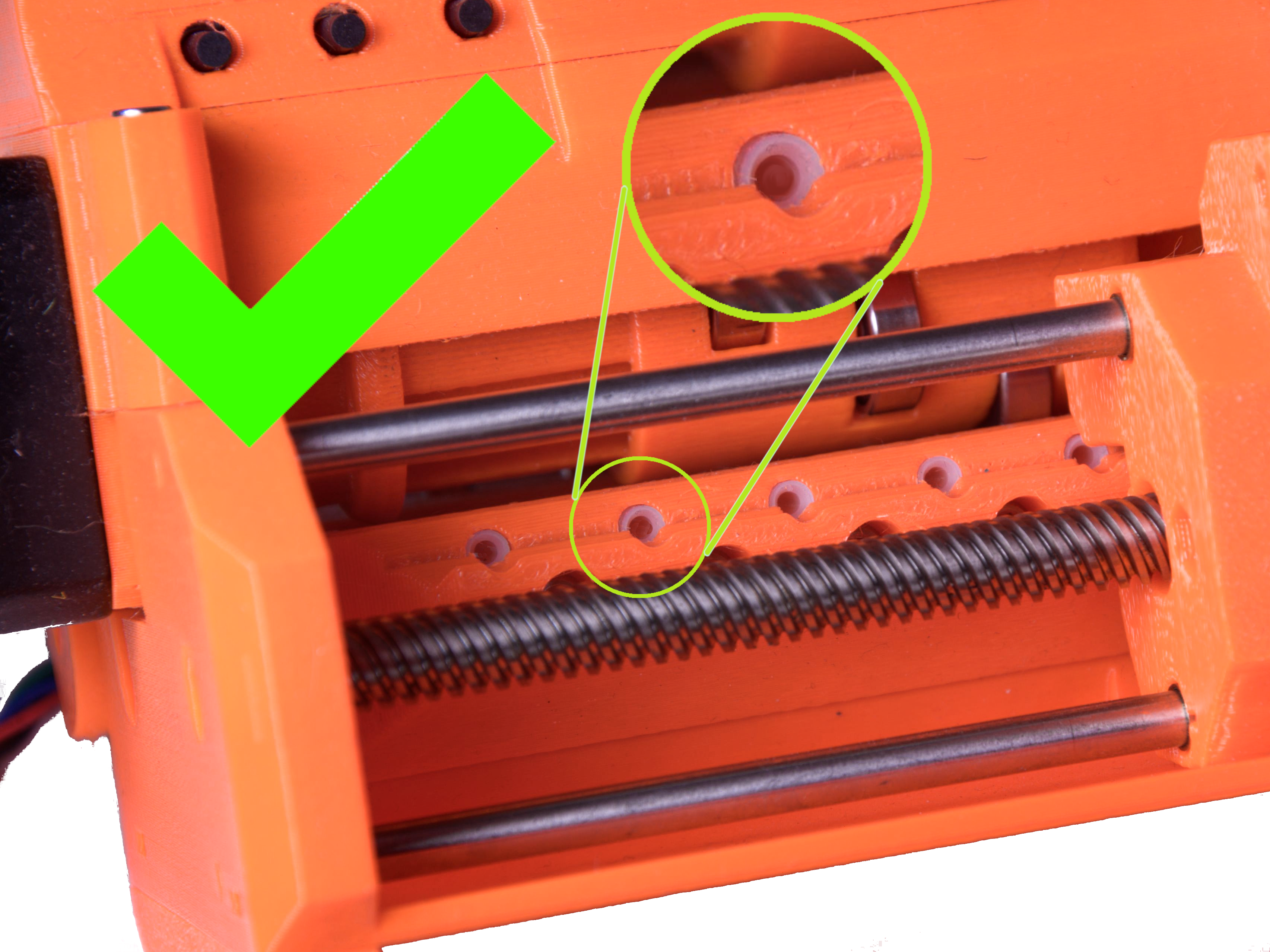
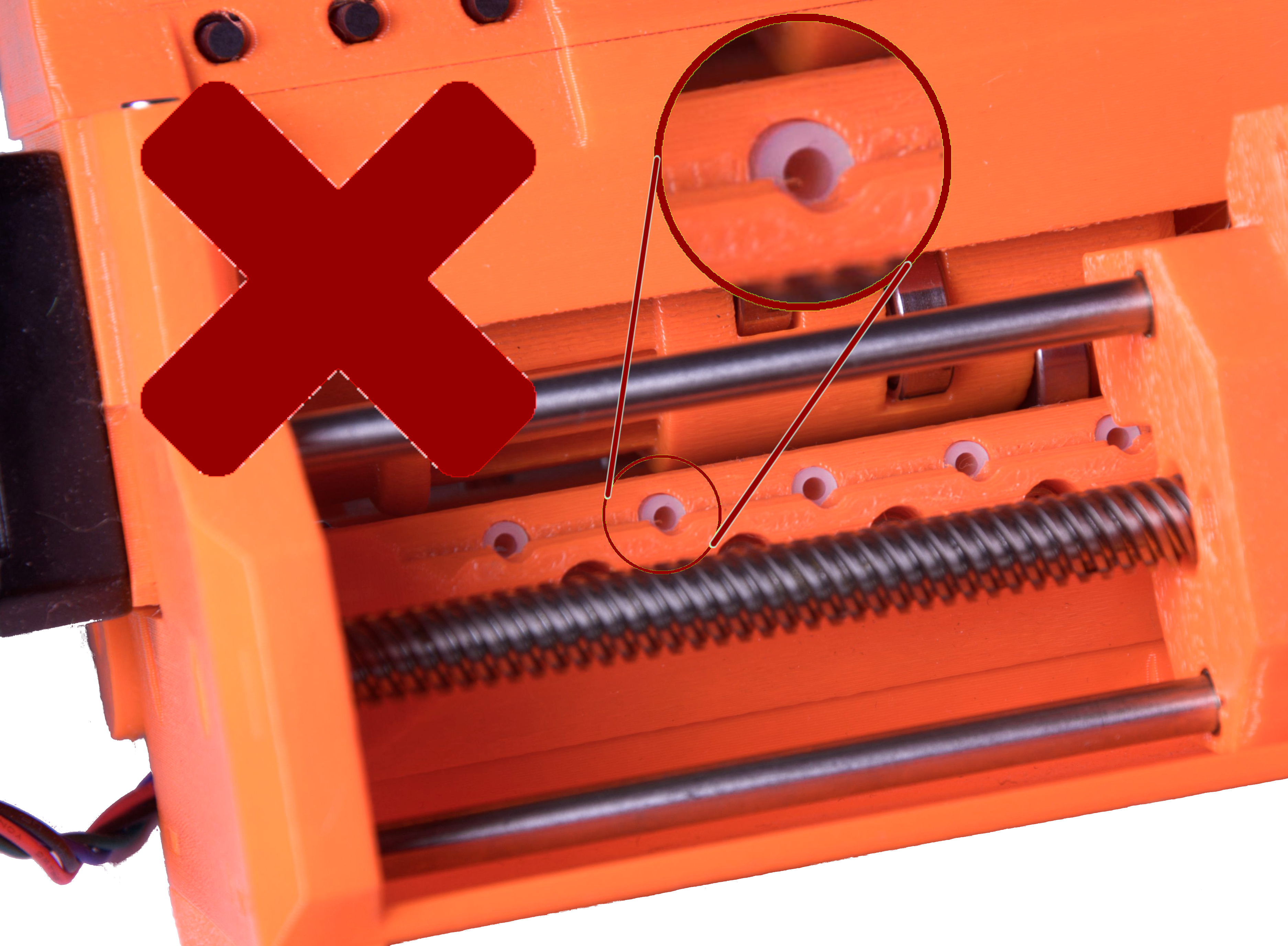
Align the pulleys
The filaments are being pushed through the MMU2S unit using 5 hobbed pulleys, mounted on the long shaft of the pulley motor. The grub screws must be:
- Oriented on the left side of the teeth, away from the Pulley motor.
- Perfectly aligned with the filament holes and filament, as shown in the photo below.
- Secured by the small black grub screw against the flat side of the Pulley motor shaft.
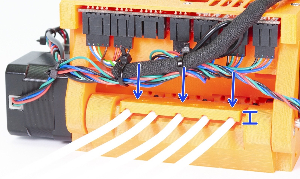
Short PTFE tubes orientation
After the filament is grabbed by the hobbed pulley, it is pushed into one of the five 19 mm (0.75 inches) PTFE tubes. These tubes are chamfered on one end, which provides some extra space for the unloaded filament, as the tip might be slightly thicker than the rest of the filament. Therefore, the chamfered end must be facing out, away from the pulleys, as explained in 5. Pulley body assembly of the Assembly manual.
 |  |
Rear PTFE holder overtightened
This holds the long PTFE tubes where you feed in filament to the MMU2S. Before tightening the four M3x18 screws, make sure that:
- The half-circular grooves are perfectly aligned with the half-circular grooves of the pulley body.
- The screws are not tightened too much, deforming the long PTFE tubes, changing their inner diameter.
- The long PTFE tubes have been inserted all the way in, past the holder, touching the Pulley body. The corresponding steps in the assembly manual are Step 13 and 14.
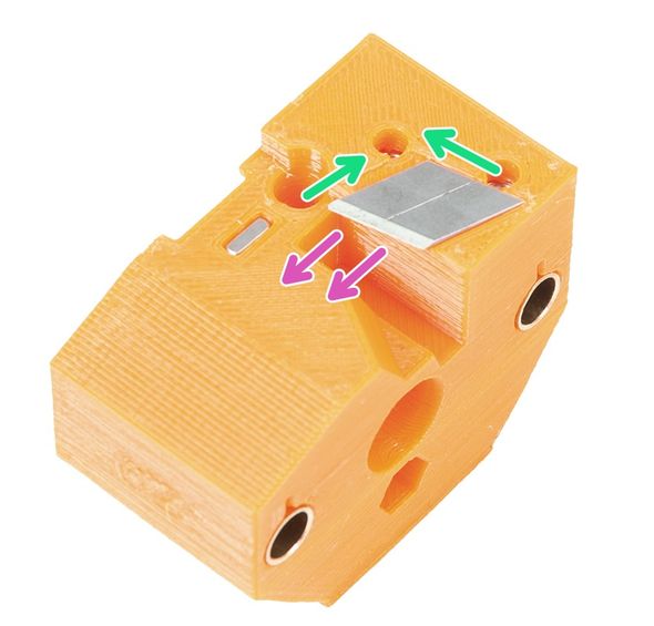
Selector blade
Make sure the little blade that is supposed to cut filament strings is secured in place with two M3x10 screws. For more info please see MMU2S Selector not moving.
 | 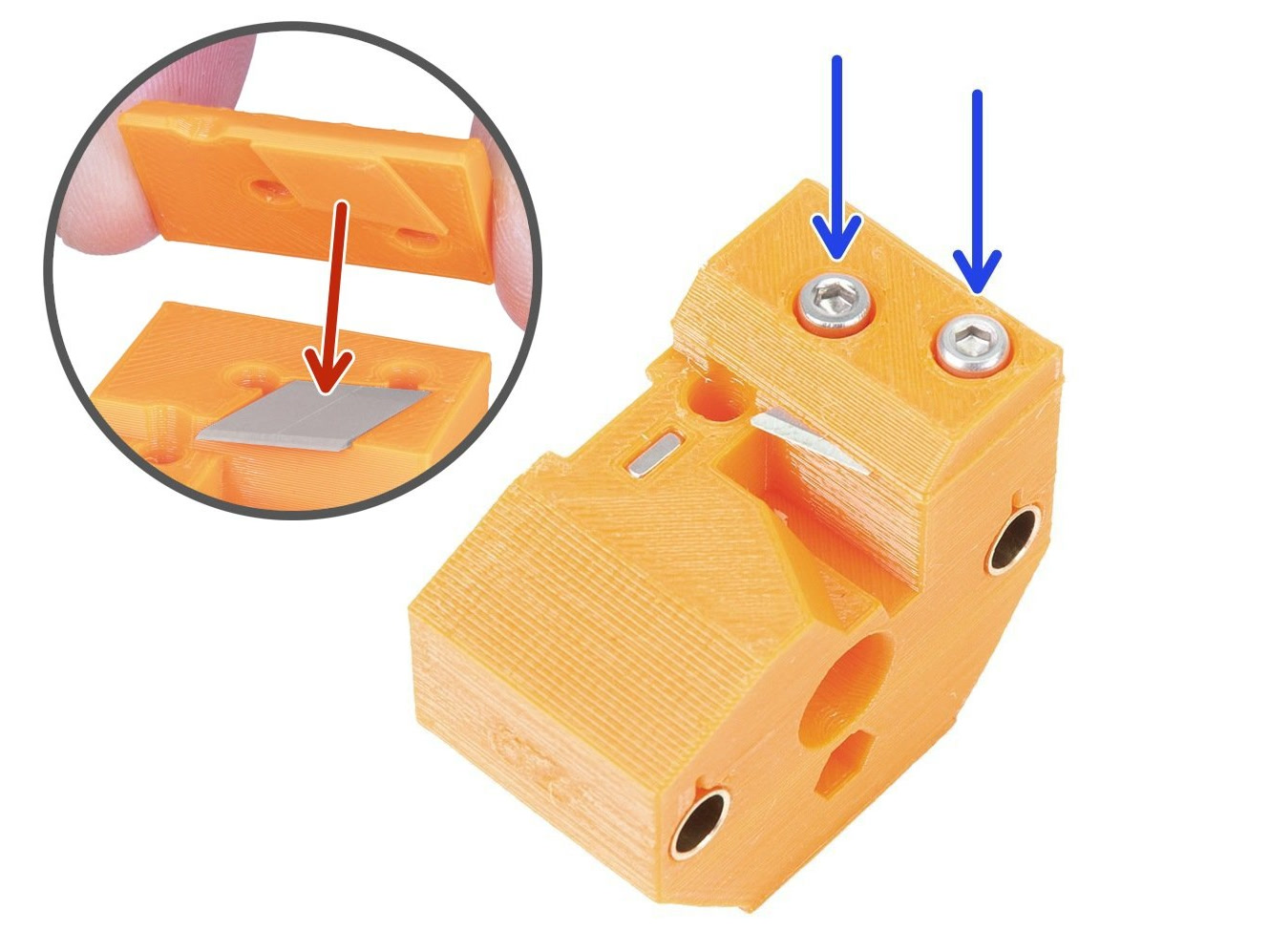 |
Slicer settings
The shape of the filament tip is very important for a successful MMU2S print. The tip should be pointy but without any lump or string. The diameter of the tip can be slightly bigger than the rest of the filament, but not by much.
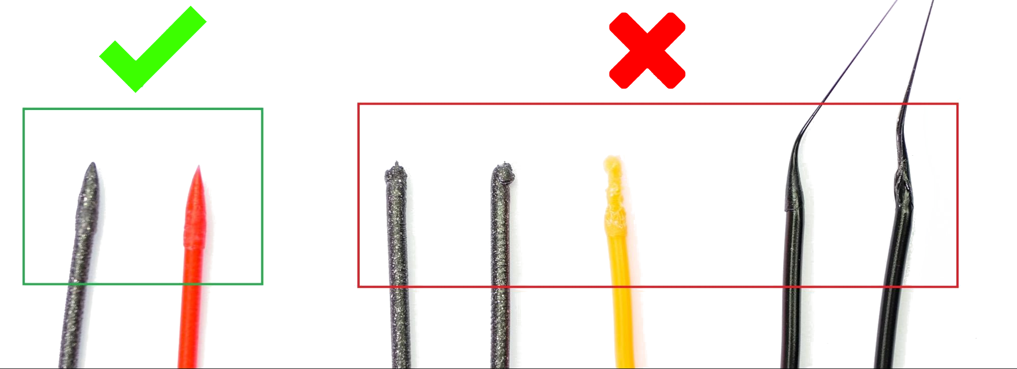
First of all, try to adjust the hotend temperature (increase or decrease it by increments of 2°C) which in most cases will solve the problem. You can do so during the print in the Tune Menu or when slicing the model.
If the problem persists, head back to PrusaSlicer and increase the number of cooling moves by 2 or 3 from Filament settings -> Advanced -> Number of cooling moves). Furthermore, you can try to increase the unloading speed by increments of 10 mm/s from Filament settings -> Advanced -> Unloading speed.
Test prints
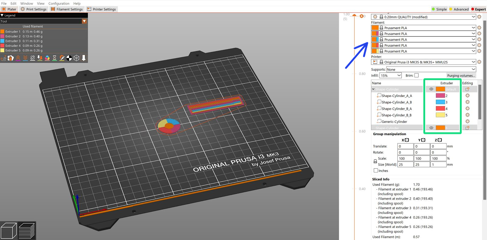
If you are sure that all potential issues mentioned above have been avoided, feel free to attempt the attached test print. Download it, and open it as a project. Before slicing the file, double-check that you set the desired materials.
The file uses all five filaments. If you intend to use less than five, modify the extruder assignment for one or more components of the object.
2 comments
Hey!
Thanks for the tip. You can prepare the G-codes for PET-G yourself, it is fairly easy! Have a look at these:
G-code preparation for MMU2S
How to prepare .stl files and G-codes for MultiMaterial Upgrade
Suggestions?