What happened?
The printer is displaying the message: Failed to reach tilt endstop, please check that the cable is connected and repeat the action.
Error name: Tilt endstop not reached
Error code: #10115
Issued when the printer did not manage to move the connecting rod as it should.
How to fix it?
The inability to home the tilt might indicate that there is a physical block of the tilt mechanism or an assembly error in the motor and the connecting rod.
- Open the eight M3x5b screws securing the cover. Be careful to unplug the USB & Power-cable before removing the cover completely.
|
|
|
|


- Remove the M4x10 screw holding the right side of the touch screen. It is not necessary to remove the left screw. Just loosen it about a half-turn and you can slide the screen out, like a door. This will give you access to the motor and connecting rod.

Be very careful with the touch screen flat cable. It is fragile and can be easily damaged or cut.
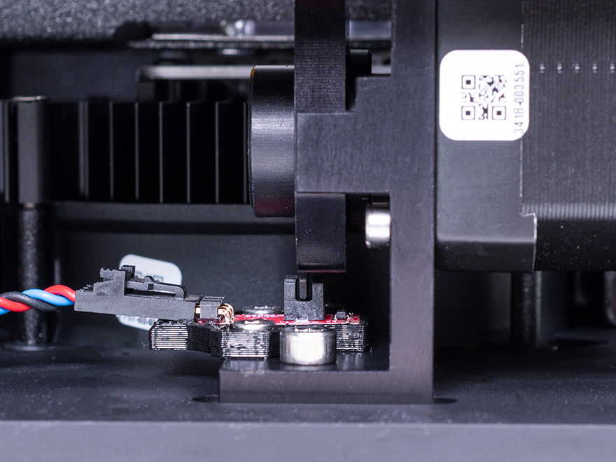
- Move the connecting rod with your hands and see if it has a full range of motion and if the blade sensor-trigger is between the two sides of the sensor. If so, jump to step 12. If any resistance is found, continue with the next step.
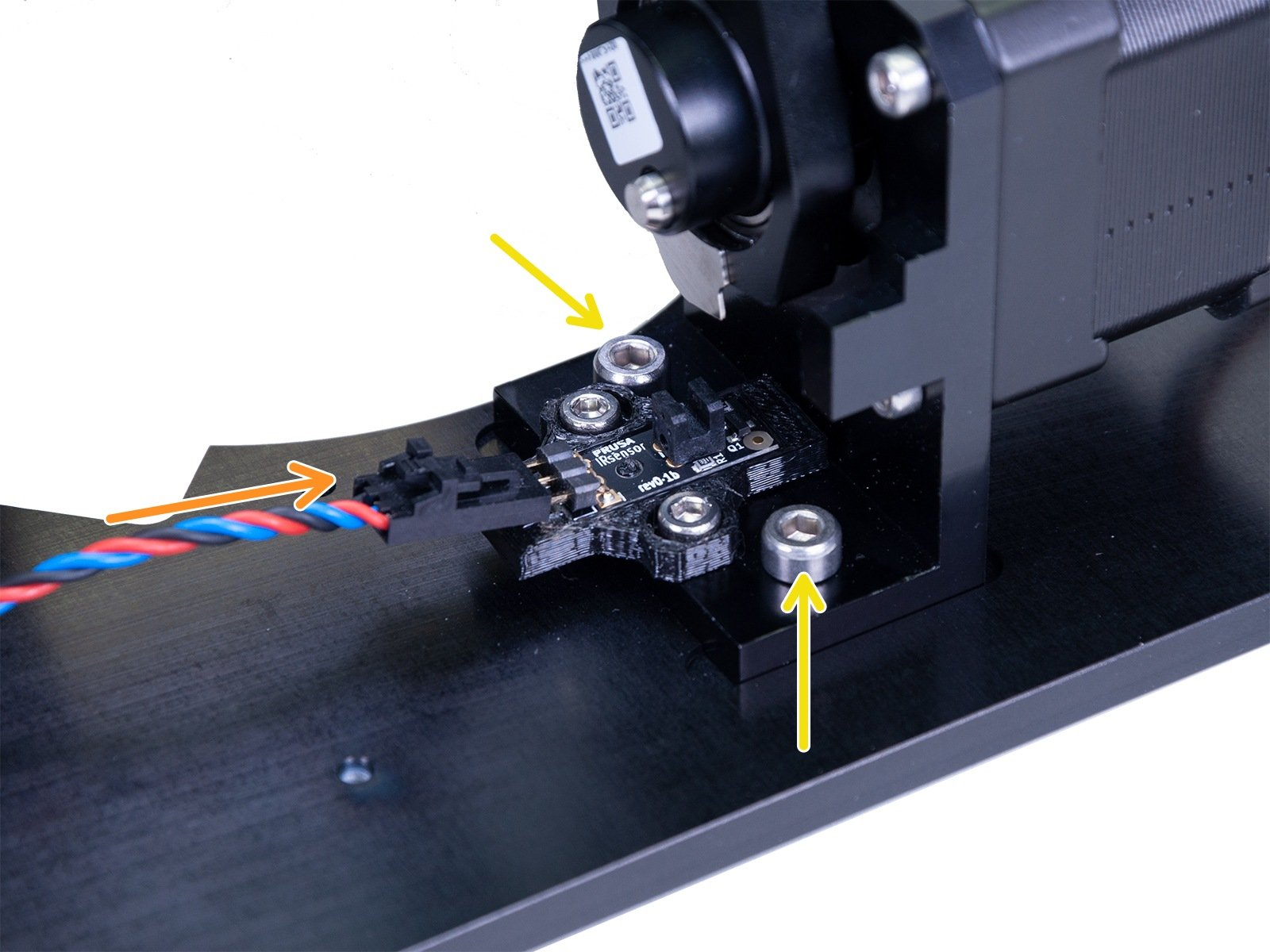
- Remove the M3nN-nut from the screw that connects the tilt-mechanism and the connecting rod. You can do that by using a spanner or pliers to hold the nut and an Allen key to unscrew from the other side.
- Remove the two M4x8 screws securing the tilt-motor holder to the bottom plate.
- Remove the motor-holder and the connecting-rod from the tilt mechanism.
- Go to Step 18 of 2. Base & Tower of the assembly guide, and remake the connection of the connecting rod and the motor shaft.

Pay extra attention to this step, as not aligning the connecting rod with the protrusion on the holder as instructed will cause the issue again.
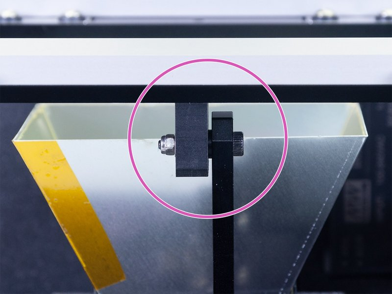
- Reassemble first the tilt to the connecting rod, make sure that after tightening the nut the two parts are in contact.

Do not over-tighten the nut!
- Connect the motor holder to the bottom plate using the M4x8 screws.

- Make sure that the optical sensor cable has its correct end connected to the sensor. The middle wire should be blue. In case the middle wire on the sensor connector is black, the connection will need to be swapped.
- Move the connecting-rod manually and see if it moves smoothly until the blade sensor-trigger is between the two sides of the sensor.
Make sure the sensor is secured!

- Slide the LCD back to its place, and tighten both M4x10 screws holding it.
- Connect the USB and Power cable and close the eight M3x5b screws that hold the cover. Tighten them diagonally at first, and add all the screws before tightening them. Pay attention to the cables from the electronics so that they are not pinched.

- Run the wizard again.
Was this article helpful?
This action is available only to registered users. Please log-in.
Log in to post a comment
No comments