AA

Featured products

    Popular categories

      Trending searches

        Articles

          Blog

            Products

              Categories

                Suggested searches

                  Searching…
                  No results
                  Something went wrong.
                  ↑↓ Select↵ OpenEsc Close search
                  • English
                  • Čeština
                  • Deutsch
                  • Español
                  • Français
                  • Italiano
                  • Polski
                  • 日本語
                  • Orders
                  • Address
                  • In-stock Alerts
                  • My Courses
                  • Subscription
                  • Edit Account
                  • 3D printers9+▾

                    3D printersnew

                    newPrusa CORE One L+Learn more
                    newPrusa CORE One+ (Gen 2)Learn more
                    newPrusa CORE One L+ INDX 8-ToolnewPrusa CORE One+ (Gen 2) INDX 8-ToolPrusa CORE One L+: Critical InfrastructureOriginal Prusa MK4SnewOriginal Prusa XL+Original Prusa XL+: Critical Infrastructure

                    Printer upgrades

                    newINDX Conversion KitsnewPrusa CORE One L to CORE One L+ upgradenewPrusa CORE One+ to Prusa CORE One+ (Gen 2)newPrusa XL to Prusa XL+ Upgrade
                    Prusa Reward ProgramLove your Prusa printer? Share your experience and earn $30 Prusa e-shop vouchers.
                    How to Choose a 3D Printer?We’ll walk you through the basics to find the exact machine for your space, budget, and ideas.
                    Free E-bookDownload a free e-book Basics of 3D Printing with Josef Prusa and make your first steps in 3D printing world
                    Original Prusa Printable PartsCollections of printable spare parts for Original Prusa 3D printers and upgrades.
                    Shipping informationRegularly updated info about the current manufacturing capacity and delivery times of our printers.
                    Custom 3D PrintingProfessional custom 3D printing from various materials according to your requirements.
                  • Materials▾

                    Filaments

                    PrusamentPLAPETGASA / ABSPC (Polycarbonate)PA (Nylon)FlexCompositesSpecialMaterials clearance sale

                    Resin

                    Prusament ResinResin Cleaner
                    Filament GuideCheck my Prusament Spool
                    Prusament.com
                  • Parts & Accessories▾

                    Accessories

                    EnclosuresNozzlesPrint SheetsEssential AccessoriesCameras & AddonsTools & CraftingAdhesives

                    Spare parts

                    Merchandise

                    Spare parts - All PrintersCORE OneMK4/S & MK3.9/SMK3/S/+XL
                    Merch
                  • For Business▾
                    Prusa Pro HT90Prusa Pro SLXPrusa Pro AFSPrusa Pro Medical OneOriginal Prusa XLOriginal Prusa XL: Critical Infrastructure
                    Prusa CORE One+Learn more
                    Prusa CORE One LLearn more
                    Prusa CORE One L: Critical Infrastructure Edition

                    3D Printing for

                    Manufacturing and R&DAutomotive IndustryHealthcareEducation and Academic ResearchArchitects and DesignersFilm IndustryCritical Infrastructure

                    3D Printing Stories

                    • How 3D printing started: About Rep-rap and open-source with Adrian Bowyer
                    • Teaching mathematics redefined with 3D printing at JKU Linz
                    • The story behind the LTT screwdriver
                    • Victoria Hand Project: Changing Prosthetic Care with 3D Printing
                    Official Prusa Resellers
                    Sustainability
                    Prusa Education
                    Contact and Inquiry
                    Custom 3D Printing
                    ISO Certified
                  • Software▾
                    PrusaSlicer

                    PrusaSlicerPrusaSlicer

                    PrusaSlicer is an open-source, feature-rich, frequently updated tool that contains everything you need to export the perfect print files for your 3D printer.

                    WindowsMacOSLinux
                    Prusa Connect

                    Prusa Connect

                    Prusa Connect is a cloud service enabling remote control and monitoring of your 3D printers, offering secure data handling, easy setup, and support for managing multiple printers from anywhere.

                    Log in to Connect
                    Prusa.app

                    Prusa.app

                    Control your printer/s remotely from anywhere using the Prusa Connect technology behind. Prusa.app brings a new level of Prusa printer experience to Android and iOS phones.

                    Try it now!
                    Drivers & FirmwareDownload the latest firmware and drivers for your 3D printer.
                    PrusaSlicer Support
                    Prusa Connect Support
                  • 3D Models▾
                    3D PrintersArt & DesignHobby & MakersHouseholdTabletop MiniaturesToys & GamesPrintables Store

                    Popular 3D models

                    • Strong garden hose holder
                    • Prusa Spool Bot
                    • Build Tray — Modular Organizer for Assembly, Disassembly and Maintenance
                    • Broom Holder
                    • Octagon Fabric
                    • Prusa CORE One ? (Mimic Skin)

                    Design Contests

                    • Réutilisation de la carte mère Framework Laptop 129/1/2026 – 9/30/2026
                    • 🏆 Défi du designer : Tours de magie !9/1/2026 – 9/22/2026
                    • Organisateurs de maquillage9/4/2026 – 9/20/2026
                  • Community▾

                    Upcoming Events

                    • 3D Printopia 20269/26/2026 – 9/27/2026 · Pennsylvania, United States · Prusa Team
                    • Maker Faire Bay Area9/25/2026 – 9/27/2026 · Kalifornie, United States · Prusa Team
                    • Hobby Messe10/2/2026 – 10/4/2026 · Sachsen, Germany · Prusa Team
                    • Mezinárodní strojírenský veletrh10/6/2026 – 10/9/2026 · Jihomoravský kraj, Czechia · Prusa Team

                    Prusa Forum

                    • LDC Screen Locked Up on Progress Screen during Print?
                    • Prusa slicer can't use multiple filaments with difference shrinkage rates?!
                    • Front Fan Wiring route
                    Prusa World MapPrusa World MapFind local 3D printing users and explore the community around you.
                  • Help▾
                    Guides & TutorialsPrusaSlicerPrusa ConnectMaterials

                    Printer Model

                    CORE One INDXCORE One LCORE One+CORE One

                    Hardware Troubleshooting

                    • Selftest failed (CORE One/+)
                    • Clogged nozzle (CORE One, CORE One L, XL, MK4/S, MK3.9/S)
                    • Adjusting belt tension (CORE One/+, CORE One INDX, CORE One L/+)
                    • Prusa Connect and PrusaLink explained

                    Drivers & Firmware

                    INDX familyCORE One familyMK4 familyXL familyMMU familyPRO family
                  • Courses▾

                    Become an expert in 3D printing

                    Prusa Academy offers online courses on various 3D printing related topics. Each course features:

                    • easy-to-read text with many pictures and short videos
                    • links for inspiration and further study
                    • quizzes for testing your knowledge along the way
                    • certificate of completion
                    Browse all coursesMy courses library
                    • 3D Modeling in Autodesk Fusion
                    • PrusaSlicer Masterclass – Beginner to Advanced
                    • Complete Guide to 3D Print Postprocessing, Painting, and Detailing
                    • Beginner's Guide to Blender for 3D Printing: Edit and Remix STLs
                  • Blog▾
                    • Prusament PLA ColorMix: Print 45 color shades using just five filament spools (and more)
                    • Back-to-School 2026 Deals Are Here!
                    • PrusaSlicer 3.0 Preview – Built for the Future of 3D Printing
                    E-Book: Basics of 3D Printing
                  • Company▾

                    About Prusa Research

                    We are the largest maker of 3D printers in Europe and the United States.

                    Founded as a one-man startup in 2012 by Josef Prusa, a Czech hobbyist, maker, and inventor. In just 15 years, we've grown into a company of more than 1,200 people. Every month, we design, build, and ship over 10,000 innovative and secure 3D printers from our headquarters in Prague, Czech Republic, and Delaware, USA, to users in more than 160 countries.

                    Watch a video and find out how Prusa Research was born and what we achieved within only 10 years!

                    About UsTimelineSustainabilityOpen-source
                    About Us
                    Contact Us
                    Logo and Photos
                    ISO Certified
                  1. Support
                  2. Original Prusa MK4S
                  3. Printer features
                  4. GPIO Module
                   

                  Contents

                  • Use-case ideas
                  • Safety first!
                  • Schematics
                  • How to install the GPIO board
                  • Pins
                  • Pull-up resistors
                  • Understanding pin values
                  • Setting GPIO via Custom G-Code
                  • How to Set Up G-code for Input Pins
                  • Advanced Input Control and Macro Triggering
                  • Custom G-Code in Prusa Slicer
                  • Examples

                  Blog

                  • Prusament PLA ColorMix: Print 45 color shades using just five filament spools (and more)
                  • Back-to-School 2026 Deals Are Here!
                  • PrusaSlicer 3.0 Preview – Built for the Future of 3D Printing

                  Newsletter

                  Signup and get our monthly squeeze on updates, blog, printables and much more.

                  By clicking, you agree to receive our newsletter.

                  This site is protected by reCAPTCHA Enterprise and the Google Privacy Policy and Terms of Service apply.

                  Strong garden hose holder
                  E-shop
                  • 3D Printers
                  • Printer Upgrades
                  • Filaments
                  • Accessories
                  • Prusa Merchandise

                  © Prusa Research a.s.

                  Printables
                  • 3D Models
                  • Store
                  • Clubs
                  • 3D Design Contests
                  • Brands
                  Community
                  • World Map
                  • Forum
                  • User Groups
                  • Events
                  Help
                  • Prusa Help
                  • Prusa Academy
                  • 3D Printing Calculators
                  Software
                  • PrusaSlicer
                  • Prusa.app
                  • Prusa Connect
                  • Drivers and Software
                  Company
                  • About Us
                  • Blog
                  • Official Prusa Resellers
                  • Contact Us
                  • Certified for ISO 9001, ISO 14001, ISO 45001
                  • General Terms and Conditions
                  • General Terms and Conditions of Use of the PRUSA Websites
                  • Privacy Policy
                  • Information about cookies
                  • Customer Complaints Policy
                  • Status Page
                  • Do Not Sell or Share My Personal Information
                  • Supplemental Statements
                  • General Terms and Conditions
                  • General Terms and Conditions of Use of the PRUSA Websites
                  • Privacy Policy
                  • Information about cookies
                  • Customer Complaints Policy
                  • Status Page
                  • Do Not Sell or Share My Personal Information
                  • Supplemental Statements

                  © Prusa Research a.s.

                  JOSEF PRUSA®, PRUSA RESEARCH®, PRUSA POLYMERS®, PRUSA ORANGE®, PRUSA 3D ® AND PRUSAMENT® are registered trademarks of Prusa Development a.s. used by Prusa Research a.s. under licence from Prusa Development a.s.

                  GPIO Module

                  Relevant for

                  CORE One family
                  MK4 family
                  MK3.5 family
                  MK3.9 family
                  48 comments
                  Article is also available in following languages
                  English
                  Čeština
                  Polski
                  Deutsch
                  Français
                  Español
                  Italiano
                  日本語

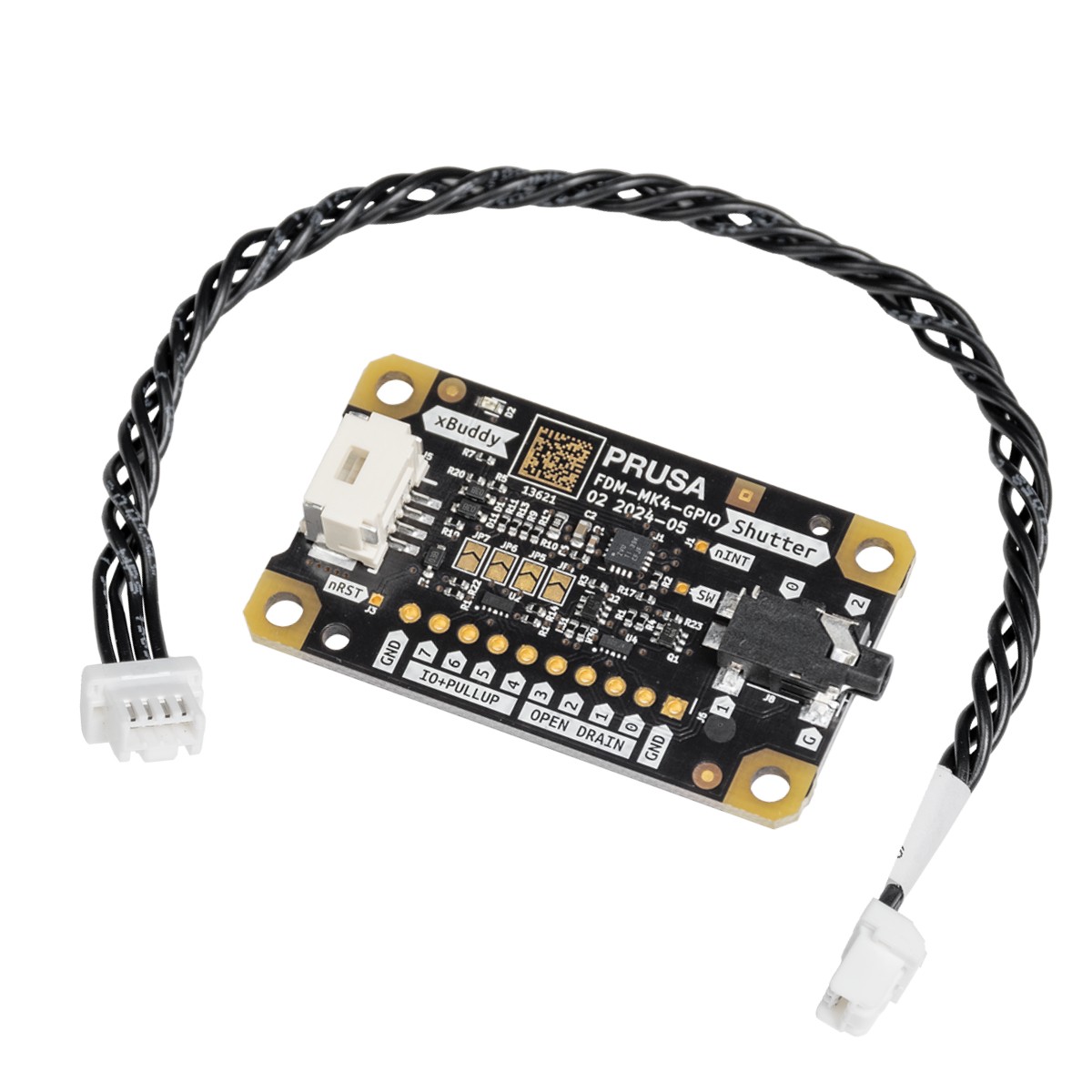
                  The GPIO module (General Purpose Input Output) is an additional, optional PCB that can be connected to the Prusa CORE One/+, and to the Original Prusa MK4/S, MK3.9/S, or MK3.5/S.

                  IMPORTANT: To utilize the full potential of the GPIO board you need firmware 6.2.0-alpha1 or newer. Visit the GitHub to download the latest firmware. 

                  The module provides expanded functionality by allowing the control of external devices through connections to the GPIO board pins, which can operate in either INPUT or OUTPUT mode. This versatility opens up a wide range of potential use cases.

                  Share and discuss your projects with the other members of the Prusa Community on our official forum. We have created a dedicated GPIO section.
                  Use-case ideas

                  The module can control a camera shutter at a precise moment, making it ideal for creating visually perfect time-lapses, where each picture is captured at the exact same point in time.

                  Beyond controlling a camera shutter, the module can be used for various other applications. For example, it can trigger external lighting to illuminate the print area at specific stages of the printing process, ensuring optimal lighting conditions for quality checks or photography. Additionally, it can be configured to activate cooling fans or other peripheral devices, such as extractors or alarms, based on custom G-Code execution during prints, helping maintain optimal operating conditions and improving the safety and efficiency of the 3D printing environment.

                  Another powerful use case is the integration of a macro keyboard, where each keypress can trigger the execution of specific G-Code commands. This setup allows for rapid manual control of the printer's functions, such as starting or pausing a print, adjusting temperatures, or moving the print head to an exact position. The ability to trigger custom actions with a simple keypress can significantly streamline workflows, making the GPIO expansion module a versatile and indispensable tool for those looking to fully customize and optimize their 3D printing setup.

                  Safety first! 

                  While the ability to trigger G-Code via GPIO inputs adds great flexibility, it also comes with limitations and potential risks. Improper use or poorly timed G-Code commands can interfere with the printing process, leading to print failures or even damage to the printer. It’s crucial to thoroughly test any custom G-Code setups in a controlled environment before deploying them in actual print jobs to avoid unintended consequences.

                  Additionally, we recommend that only experienced users with a solid understanding of electronics and G-Code manipulation utilize this GPIO module, as improper connections or configurations can result in hardware damage or safety hazards.

                  Schematics 

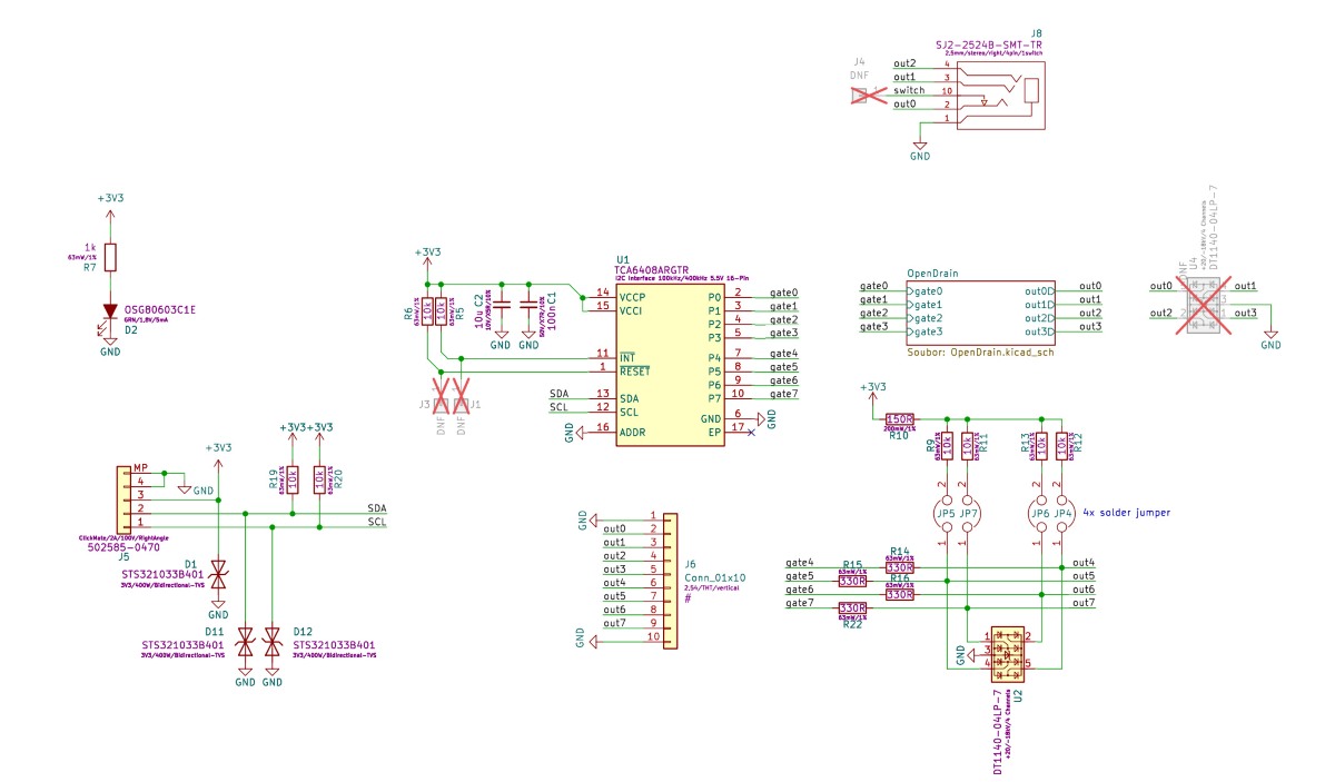
                  The schematics are open source, and available on our page Open Source at Prusa Research. 
                  How to install the GPIO board

                  1. Ensure the printer is cooled down to room temperature, and switch it off.
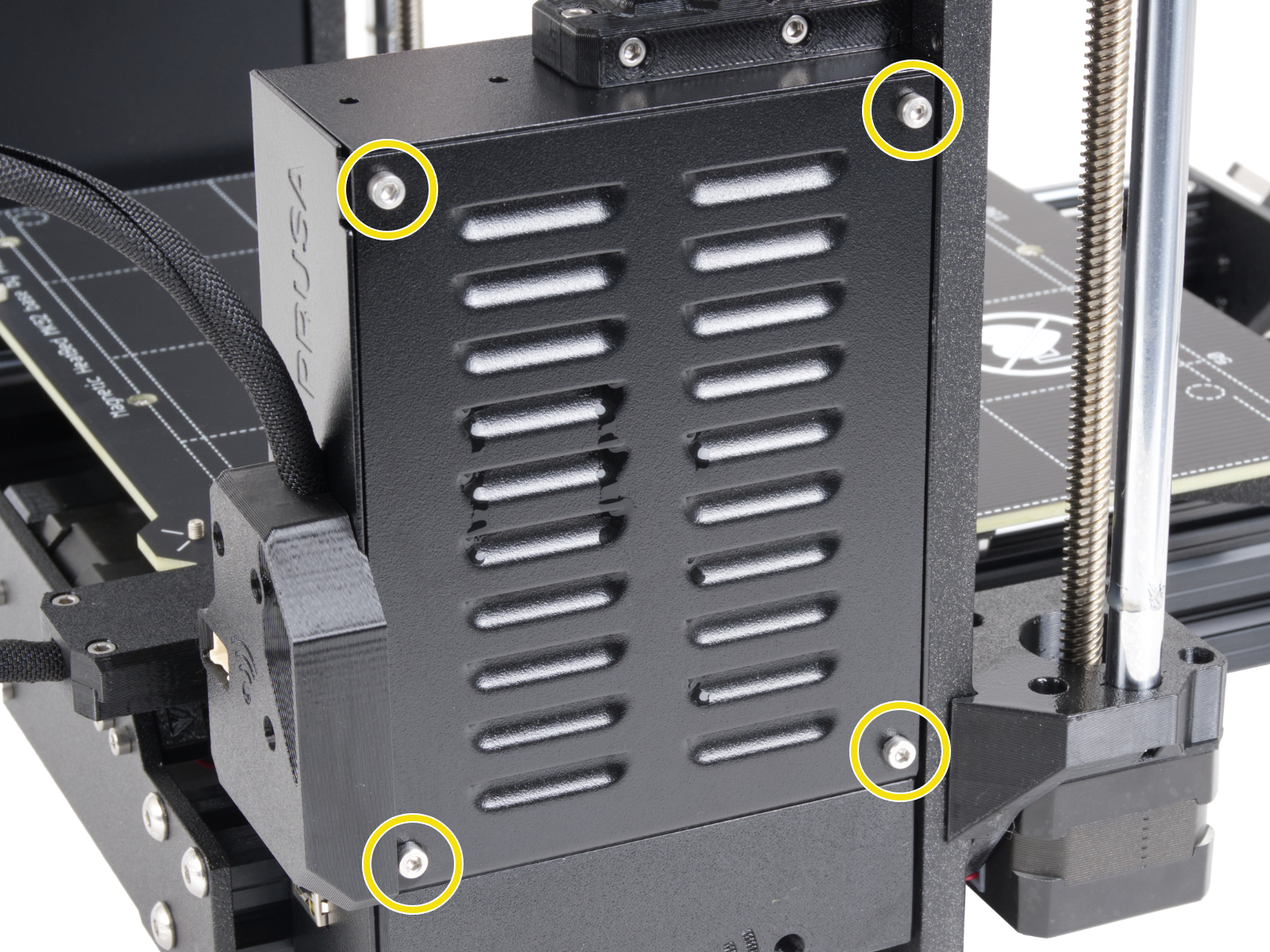
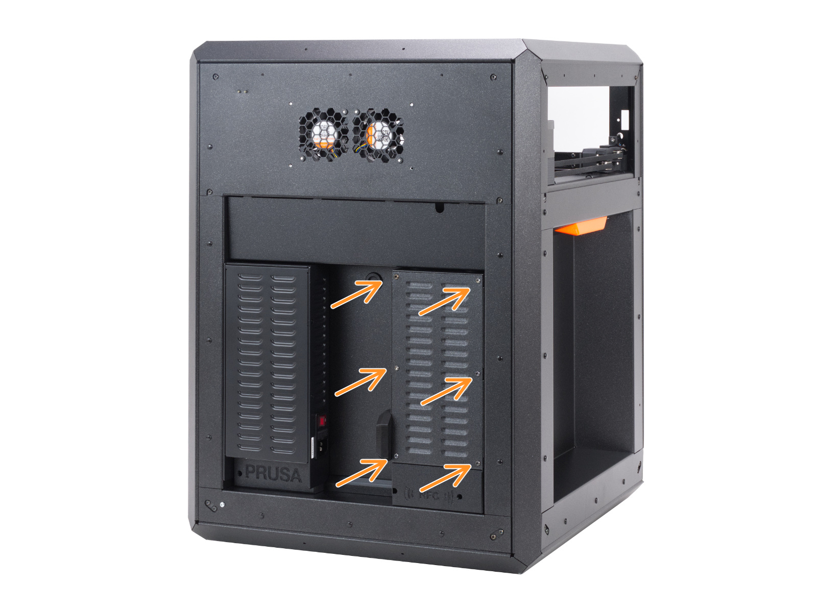
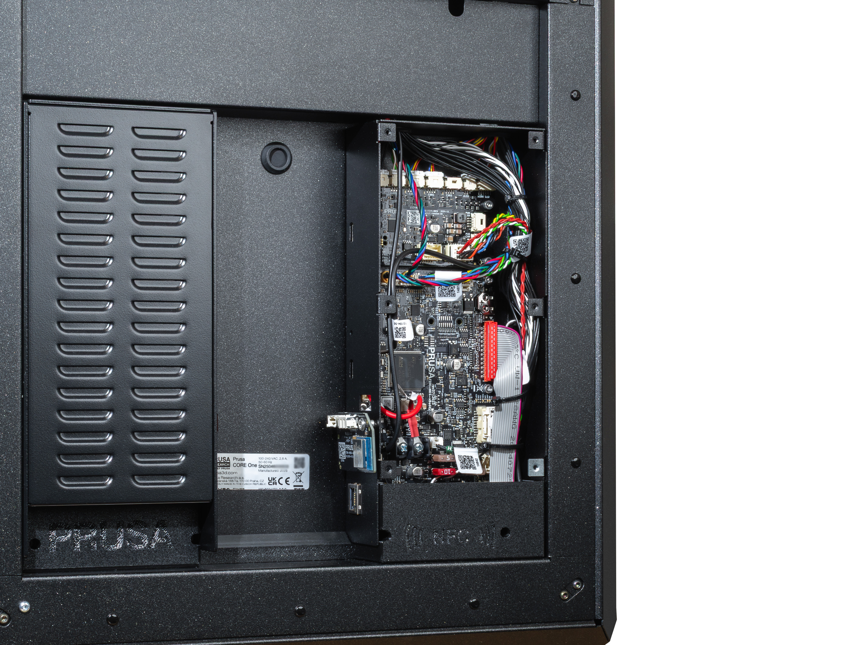
                  2. Open the xBuddy box cover by removing four M3x6 screws (MK-series), by removing six M3x4bT bolts (CORE One). 
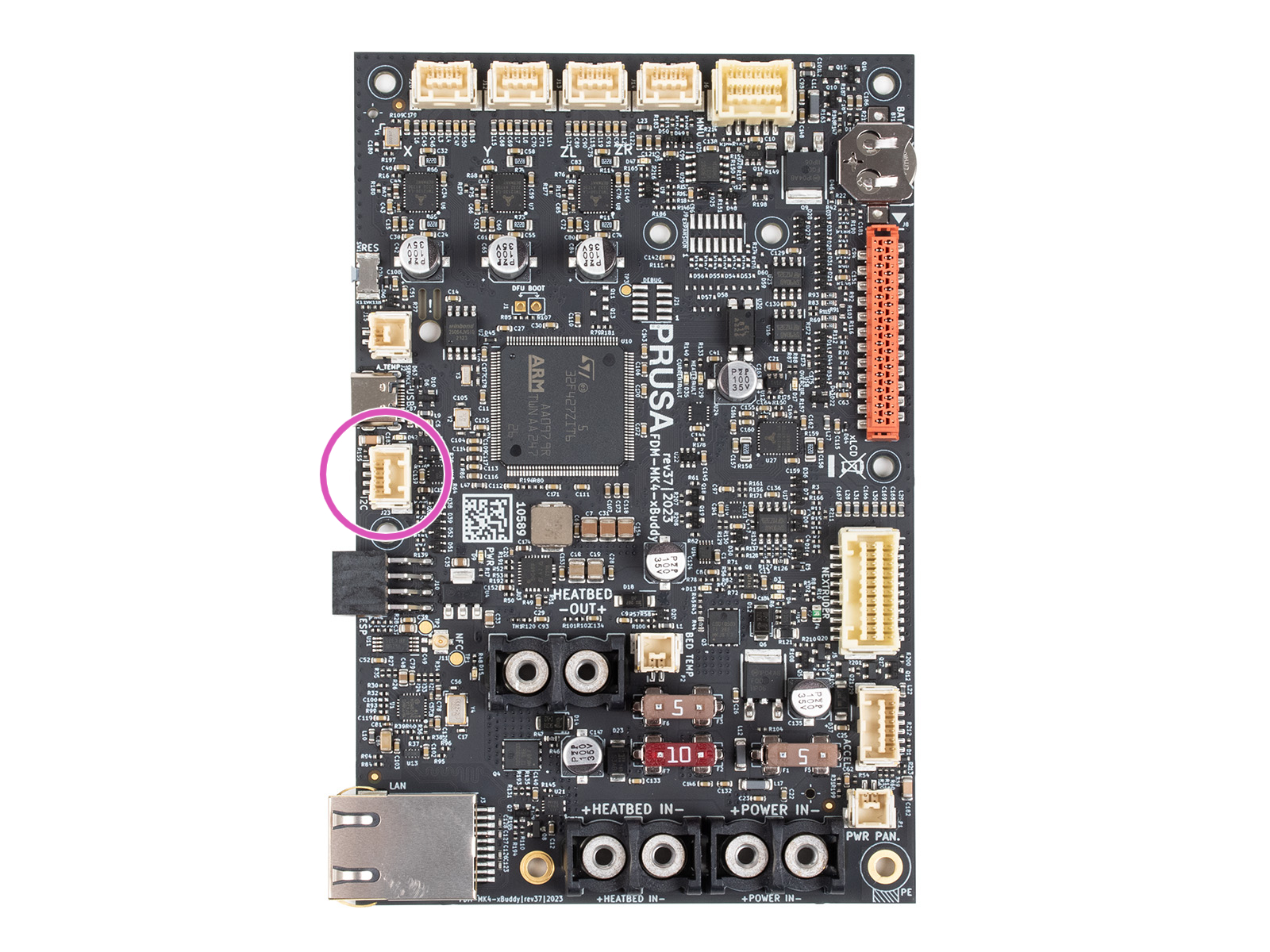
                  3. Connect the GPIO cable to the I2C port.
                  4. Close the xBuddy box cover.
                  5. Ensure that the GPIO does not touch any metal parts of the xBuddy box or its cover. 
                  6. Enjoy your project!

                  Pins

                  Limits - output mode

                  PIN 0 to 3 -> switch max. 24V, 500mA (to ground)
                  PIN 4 to 7 -> switch 0V or max. 3.3V, 10mA

                  Limits - input mode

                  PIN 4 to 7 -> 0V or 3.3V (max short-circuit current: 0.5mA with < 4 kΩ resistance).

                  Description

                  The board features 8 pins, numbered 0-7. Pins 0-3 can be used as output, and pins 4-7 can function as either input or output. Each pin is of the open-drain type when used as an output, meaning it is controlled by a transistor that connects the pin to the ground (0 V) when active. When the pin is inactive, it remains "floating", which means it is not connected to any specific voltage, but due to internal pull-up resistors, the voltage on the pin can hover around 3.3 V. 

                  It is possible to solder external pull-up resistors to the JP pins. This changes the behavior described above. For more details on that, see the pull-up resistors paragraph below. 

                  The behavior of the pins in an open-drain state when used as outputs can be explained as follows:

                  • Pin set to 0 (LOW): The pin is turned off and is in a "floating" state, which means it is not connected to any specific voltage. In this state, the voltage on the pin can fluctuate and is not well-defined unless stabilized by a pull-up resistor.

                  This "floating" state may cause the pin to pick up random electrical noise or interference, leading to unintended behavior if not properly managed. 

                  • Pin set to 1 (HIGH): The pin is turned on and connected to the ground (0 V), causing the voltage on the pin to drop to 0 V. This state is clear and does not lead to any ambiguity in signal detection.

                  When the pins are used as inputs, they can detect the voltage level applied to them. The input state is influenced by the presence of pull-up resistors, which can help ensure a consistently high voltage (3.3 V) when no other voltage source is applied.

                  Pull-up resistors

                  The board allows the connection of external pull-up resistors via solder jumpers labeled JP4 to JP7. These solder jumpers are located in the center of the board and are connected to the corresponding pins:

                  • JP4 is connected to Pin 4
                  • JP5 is connected to Pin 5
                  • JP6 is connected to Pin 6
                  • JP7 is connected to Pin 7

                  Solder jumpers JP7 to JP4 can be used to connect integrated pull-up resistors, which ensures that the pins remain at a high voltage (3.3 V) when not actively driven low by an external source or by the pin's output state. These pull-up resistors have a value of 10K ohms, which is a standard value to provide stable voltage without excessive current draw.

                  If the jumper is not soldered, the pin may remain in a floating state, potentially leading to unstable behavior. JP stands for "jumper": if the jumper is not soldered, the stabilizing 10 kOhms resistor is not connected to the gate and its signal. 

                  For less experienced users, it's important to understand that open-drain outputs do not inherently produce a high voltage (3.3 V) but rather allow a connection to ground (0 V). Pull-up resistors are necessary to ensure that the pin remains at a high voltage when turned off or when used as an input. If not properly managed, a "floating" voltage can cause the pin to pick up electrical noise, leading to unwanted switching or system instability.

                  Understanding pin values

                  To use advanced registers or read multiple pins at once, the board uses a binary-to-decimal system. Each pin has a unique numerical "weight." To target multiple pins, add their weights together.

                  Pin01234567
                  Weight1248163264128
                  • Example: if you want to use Pin 0 and Pin 1, the value is 1 + 2 = 3
                  • Example: to set all pins (0-7) at once, the value is 255

                  Setting GPIO via Custom G-Code

                  General Information

                  The following is a sequence of custom G-Code commands used for controlling the GPIO board. This allows you to configure output states, read input states, and manage other advanced settings on the board through G-Code instructions, integrating them seamlessly with your 3D printer’s workflow.

                  Pin control via G-Code

                  To control the output pins on the GPIO board, you can use the following G-Code commands:

                  1. Set Pin Mode (Output or Input)
                    • P<0-7>: Select the pin number to configure (from 0 to 7).
                    • B<0 or 1>: Set the pin mode.
                      • 0 - configures the pin as an output
                      • 1 - configures it as an input.
                    • Example: M262 P0 B0 - Configures pin 0 as an output pin.
                       
                  2. Write state to an Output Pin
                    • P<0-7>: Select the pin number to write to (from 0 to 7).
                    • B<0 or 1>: Write 0 to set the pin to LOW (0 V) or 1 to set the pin to HIGH (3.3 V).
                    • Example: M264 P0 B1 - Sets output pin 0 to HIGH (1).
                       
                  3. Toggle state of Output Pin
                    • P<0-7>: Select the pin number to toggle (from 0 to 7).
                    • This command flips the current state of the selected pin.
                    • Example: M265 P0 - Toggles pin 0.
                       When using M267, the R parameter selects the "folder," and the B parameter provides the pin map:
                  4. Advanced Register Setup (For Experienced Users)

                  When using M267, the R parameter selects the "folder," and the B parameter provides the pin map:

                    • R<1-3>: Select the register to configure:
                      • 1: Output Register. Sets the voltage for output pins. 0 = Low (0V), 1 = High (3.3V).
                      • 2: Polarity Register. Defines logic. 0 = Normal, 1 = Inverted. Useful for preventing "ghost" triggers on pins 0-3.
                      • 3: Configuration Register. Defines direction. 0 = Output, 1 = Input. (e.g., B255 makes all pins inputs).
                    • B<0-255>: Set the value to be written to the selected register.
                    • Example: M267 R3 B255 - Configures the Configuration Register with the value 255 (all pins set to inputs).

                  To read the state of pins or set up configurations, use the following G-Code commands:

                  1. Read state of Pin
                    • P<0-7>: Select the pin number to read from (from 0 to 7).
                    • The returned value will indicate whether the pin is HIGH (1) or LOW (0).
                    • Example: M263 P6 - Reads the state of pin 6 (returns 32 for HIGH or 0 for LOW).
                       
                  2. Read Entire Input Register
                    • This command reads the entire input register, returning a number in given "style" format that represents the states of all input pins (from 0 to 7).
                    • Possible states are:
                      • 1 - HEX DUMP
                      • 2 - signed two byte integer, base 10 (int16)
                      • 3 - unsigned byte, base 10 (uint8)
                    • device address is always 32
                    • Example: M261 A32 B1 S3 - reads the entire input register and returns it as unsigned byte base 10
                       
                  3. Read IO expander's register (For Experienced Users)
                    • this reads the whole byte of the given register at once
                    • R<0-3>:
                      • 0 - Input
                      • 1 - Output
                      • 2 - Polarity
                      • 3 - Config
                    • Example: M268 R3 - Reads Config register

                  Interpreting Read Results

                  When you read a register (M268) or the entire input (M261), the printer returns a single number. Use the weight table to decode it. 

                  Note on M261: This command is for communicating with external I2C "Slave" devices connected to the board. Address 32 is the GPIO board itself; other addresses depend on the specific hardware you attach.
                  Pin01234567
                  Weight1248163264128

                  Examples

                  • If M268 R0 returns 64, Pin 6 is active.
                  • If it returns 192, then both Pin 6 (64) and Pin 7 (128) are active (64+128=192).

                  How to Set Up G-code for Input Pins

                  To configure input pins for your setup, each input pin is automatically mapped to a specific G-code file located on the USB drive. These files must be stored in a folder named "macros" and follow a strict naming convention: the file name must be in the format

                  where {pin_number} corresponds to the specific GPIO pin you are using. All letters in the file names must be lowercase.

                  For example:

                  • if you are using pin 7, the corresponding G-code file must be named btn_7.gcode and placed in the "macros" folder.
                  • similarly, for pin 4, the file should be named btn_4.gcode

                  The system supports 8 input pins on the GPIO board, and each pin can be mapped to a unique G-code file in this way.

                  When a G-code file is triggered via its corresponding input pin, the G-code stored in that file is immediately injected into the ongoing process. Please note that there is a size limit for each G-code file, which must not exceed 1024 bytes.

                  While the naming convention (btn_x.gcode) is fixed, the content of the file is limited only by the Prusa firmware.

                  You can inject any valid G-code. This includes M600 (filament change), M112 (emergency stop), M104 (temperature changes), or G28 (homing).
                  Limitations: Macros are injected into the current command stream. The system does not currently support software-based triggers (e.g., "run macro when print finishes"); triggers are strictly physical via the input pins.

                  Advanced Input Control and Macro Triggering

                  When an input pin is configured using M262 and set to 1 (input mode), the state of the pin is periodically checked every 0.5 seconds.

                  If a button connected to the pin is pressed (pin state goes LOW), it triggers a macro button. For example, a button on pin 7 can automatically execute a macro stored in the file macros/btn_7.gcode on a USB drive. The macro is injected into the print sequence, with a size limit of 1024 bytes.

                  Persistent Memory

                  Configuration of the pins and their states are stored in EEPROM, ensuring that pin settings (output/input modes, polarity, and states) are preserved even after a power cycle.
                  Changes made via M262, M264, M267, or any other relevant G-Code will update the EEPROM, so the settings are persistent.

                  Edge Cases

                  For pins 0-3, which lack internal pull-up resistors, configuring them as input without additional external circuitry may result in an inverted logic state. This can inadvertently trigger macro execution due to their default idle state being LOW (0).

                  You can invert the logic of input pins using the Polarity Register (M267 R2 B<value>). This feature is particularly useful for pins that do not have pull-up resistors (pins 0-3), which default to an idle state of 0 (LOW) and might trigger unwanted actions when left unconfigured.

                  All pins (0-7) support polarity inversion equally. This means you can invert the logic for any pin, which is configured as input.

                  The primary difference in behavior between the pins comes from the fact that pins 4-7 can utilize internal pull-up resistors, which hold them at a HIGH state (3.3 V) when not actively driven LOW. However, these pull-up resistors are only active if the corresponding solder jumpers (JP4 to JP7) are connected. If these jumpers are not soldered, pins 4-7 behave similarly to pins 0-3, defaulting to a floating state.

                  When using input pins to trigger macros, the system is designed to detect a LOW state as indicating a pressed button. For pins without active pull-up resistors, this default LOW state can inadvertently trigger macros unless polarity inversion is used.

                  Warnings and Limitations

                  When configuring or writing to pins, the system outputs a warning via the serial port if there is a mismatch between the intended operation (e.g., trying to write to an input pin). It is essential to correctly configure pins using M262 to avoid such conflicts.

                  Custom G-Code in Prusa Slicer

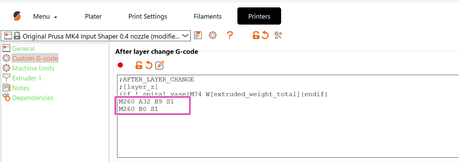
                  Insert the code in the exact spots where it is needed, after/before another particular G-Code command. In the example screenshot, the custom G-Code that controls the GPIO board is set through PrusaSlicer and is positioned after each layer change. However, it can be positioned at any point. 
                  Examples

                  Sample Connection of GPIO Module to Addon Controller (Fan Filter and LED)

                  In the image attached below, we can see the connection between the GPIO module and the addon controller responsible for controlling the Original Prusa Enclosure's fan filter and LED. 
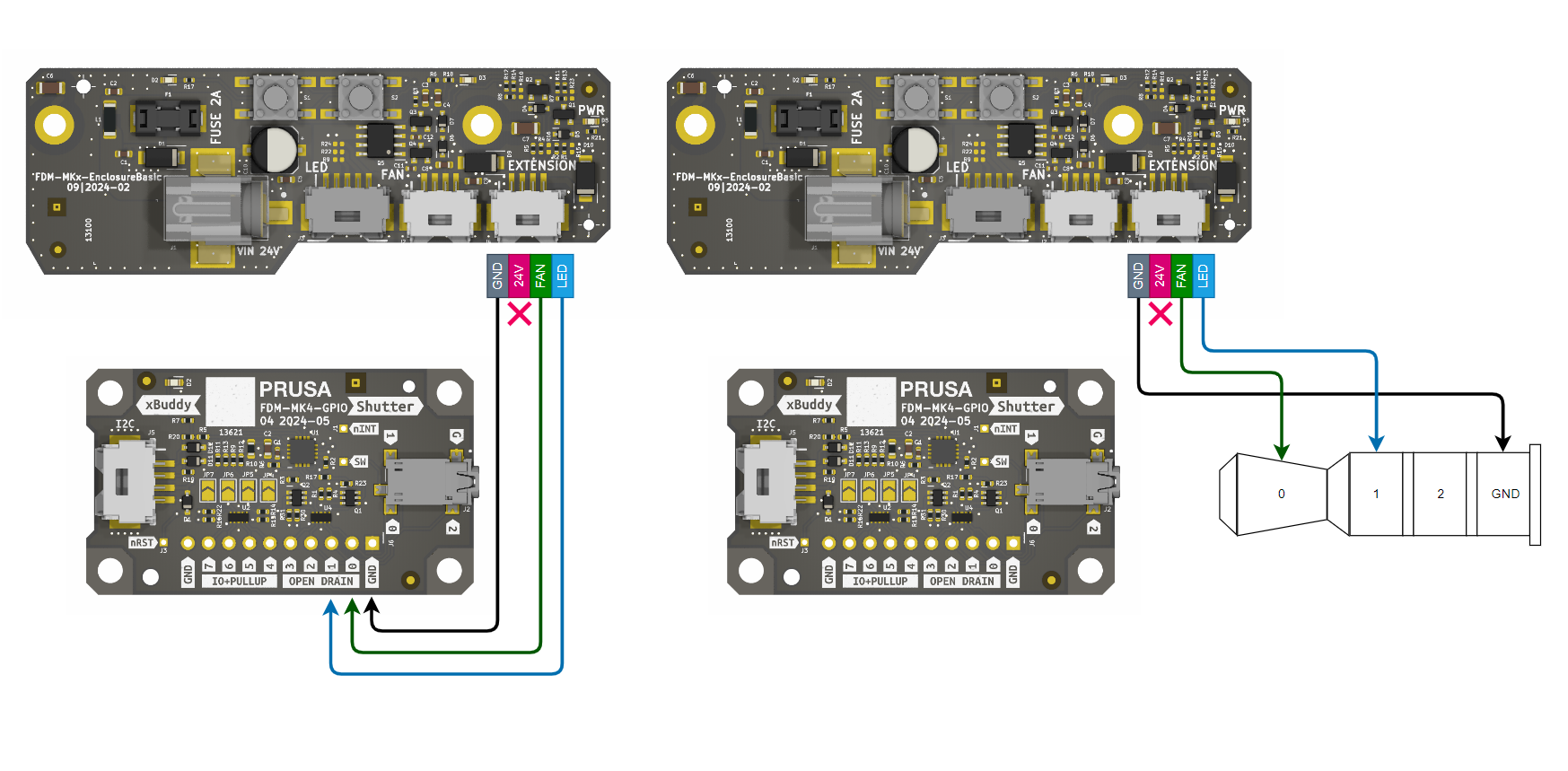
                  We are currently developing a jack-to-molex cable solution for connection between the GPIO board and the EnclosureBasic board. This will provide an easy and user-friendly way to manage the enclosure’s controls.

                  Image of example setup for enclosure

                  Connecting the GPIO board to the Addon Controller allows the printer to automate enclosure features. Example: 

                  Direction: Set the connecting pin (e.g., Pin 0) to output: M262 P0 B0.
                  Automation: In PrusaSlicer, go to Printer Settings > Custom G-code.

                  Start G-code: Add M264 P0 B1 to turn on the enclosure lights/fan when the print begins.
                  End G-code: Add M264 P0 B0 to turn them off when finished.

                  Was this article helpful?
                  This action is available only to registered users. Please log-in.

                  Topics

                  • About your printer
                    • Printer features
                      • Steel sheet profiles
                      • Flexible steel sheets (guidepost)
                      • Power-modes
                      • IR Filament Sensor (MK2.5S, MK3S/+, MK3.5/S)
                      • Experimental settings (MK4/S, MK3.9/S, MK3.5/S, XL/+, MINI/+)
                      • Loadcell (MK4/S, MK3.9/S, XL/+)
                      • Status LED explained (MK4/S, XL/+)
                      • Nextruder filament sensor (CORE One, CORE One L, MK4/S, MK3.9/S, XL/+)
                      • Buddy firmware-specific G-code commands
                      • Nextruder silicone sock (CORE One/+, CORE One L/+, XL/+, MK4/S, MK3.9/S)
                      • Model preview
                      • Cancel Object (MK4/S, MK3.9/S, XL/+, CORE One+/GEN 2, MINI/+)
                      • Touch screen (CORE One L, CORE One, MK4/S, MK3.9/S, MK3.5/S, XL/+)
                      • NFC antenna
                      • Accelerometer (CORE One, MK4/S, MK3.9/S)
                      • GPIO Module
                      • Network Connection (CORE One L, CORE One, MK4S, MK3.9S)
                      • MMU3 Prusa Nozzle vs. CHT nozzle
                      • Flashing custom firmware (CORE One L, CORE One, MK4/S, MK3.9/S, MK3.5/S)
                      • Safety and safety timer messages (CORE One, CORE One L, XL, MK4/S, MK3.9/S, MK3.5/S)
                      • Advanced filtration system for Prusa CORE One
                      • Prusa CORE One to CORE One+ upgrade (community version)
                    • Printer description
                    • General Information

                  24 comments

                  Log in  to post a comment
                  KmanSweden
                  •
                  Any update on the "jack-to-molex cable solution for connection between the GPIO board and the EnclosureBasic board" project?
                  Reply
                  Amtshofmann
                  •
                  I am looking for an instruction how and where to install the gpio board. In the section "How to install the GPIO board" above I have seen only an instruction where to plug in the cable.
                  Shall the board be installed inside or outside of the xBuddy box?
                  The board contains screw holes at all 4 corners. Is there a place prepaired where to fix appropriate screw?
                  Reply
                  Thunderhead
                  •
                  Bad idea to put it inside the buddy box without some proper isolation. IE: if any of the circuitry makes contact with other circuits on the buddy board... well... I don't want to see that happen to anyone.

                  Better off to run it outside the buddy box: print an enclosure for it and then attach it somewhere that's out of the way but still accessible so that you can tinker:
                  https://www.printables.com/search/models?q=Prusa+GPIO
                  Reply
                  Milan Huf
                  •
                  Hello,

                  Please, when will the cable jack to molex for gpio be available? Tank you
                  Reply
                  Olivier COLLET
                  •
                  I used to have a Raspberry/Octoprint on my Mk3s to monitor temperature of Enclosure / Supply / Electronic box plus some relays to control leds and cut printer powers in case of emergency. This plus a video monitoring with a cheap camera.
                  All these beeing controled with simple buttons on the excellent Octopod application.

                  Now I upgraded to Mk3.5S and enjoy Prusa connect BUT I lost all these fonction

                  Is it possible to do the same (at least 2 relays control and 3 temperatures monitoring) with this hacker’board and to read the values / control the relays on Prusa Connect app?

                  Where can I find informations ?

                  Thanks!
                  Reply
                  Schehlein
                  •
                  The page ends with "Setting GPIO via Custom G-Code". Where can we find the rest like "How to Set Up G-code for Input Pins", "Advanced Input Control and Macro Triggering" and "Examples"?
                  Reply