This article guides you through the community version of the Prusa CORE One to the Prusa CORE One+ upgrade. It lists all the components required for the upgrade and provides instructions for each relevant part of the printer. Some parts need to be printed, and a few additional components must be sourced, most of which are readily available from standard hardware stores.
New key features of CORE One+
- Automatic grille opening adjusts the chamber ventilation based on the internal temperature. This ensures that the environment is optimal for the materials being printed, helping to reduce warping and improve adhesion.
- Advanced side filament sensor featuring a hardware switch to ensure reliable, snag-free feeding of TPU filaments.
Which parts can be upgraded
- Nextruder & Top panel for vent grille automation
- Side filament sensor
- Spool holder
Required components
Printed parts
The following printed parts must be prepared before starting the upgrade. Depending on the part's function and exposure to heat or stress, different materials are recommended. Below is a list of all printed parts along with the suggested material type for each.
| Printed part | Recommended material |
| C1+ FILAMENT SENSOR BODY | PETG Jet Black |
| C1+ FILAMENT SENSOR COVER | PETG Jet Black |
| C1+ FILAMENT SENSOR LEVER | PETG Jet Black |
| Puck Universal | PETG Jet Black |
| Spoolholder static | PETG Jet Black |
| C1+ FILAMENT SENSOR SWITCH | PETG Orange |
| C1+ UPG VENT BLOCK B | PCCF |
| C1+ PRINTHEAD COVER RIGHT LEVER | PCCF |
Recommended print settings for PETG parts
- Layer height: 0.2 mm
- Infill: 20%
- Infill pattern: Grid
- Brim: Optional (recommended for very small parts)
Recommended settings for PCCF parts
C1+ UPG VENT BLOCK B
- Layer height: 0.2 mm
- Infill: 20%
- Infill pattern: Grid
- Brim: Recommended
C1+ PRINTHEAD COVER RIGHT LEVER
- Layer height: 0.2 mm
- Infill: 50%
- Infill pattern: Grid
- Perimeters: 3
- Brim: Recommended
Mechanical parts and fasteners
| Part | Amount | Note |
| Magnet 10x6x2 | 2 | You can either remove them from the old part or purchase new ones in our eshop. |
| O-ring 25x3.5 mm | 1 | Recommended type: EPDM 70 ShA. |
| M3nS nut | 2 | You can either remove them from the old part or purchase new ones in our eshop. |
Upgrade instructions
Before you start, read the entire upgrade guide before disassembling your printer.
Make sure you have:
- all required replacement parts,
- all printed parts prepared,
- all the required tools,
- a clean and well-lit workspace.
Nextruder upgrade
The following instructions will guide you through installing the lever for automatically opening the top grille on the Nextruder.
- To access the Nextruder from above, first remove the top panel as described in the separate guide Top Cover Removal.
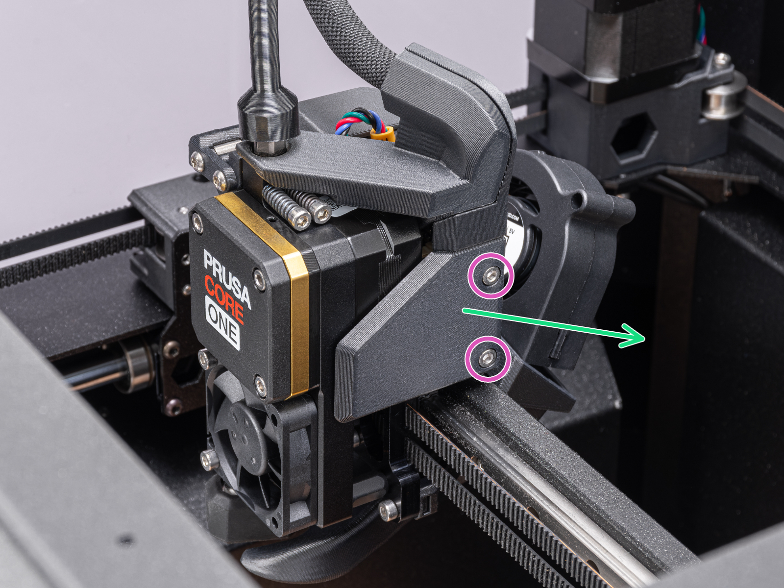
- On the right side of the Nextruder, loosen the two M3 screws securing the Print-head-cover-right.
- Remove the Print-head-cover-right. You can discard the Print-head-cover-right, as it will no longer be needed.
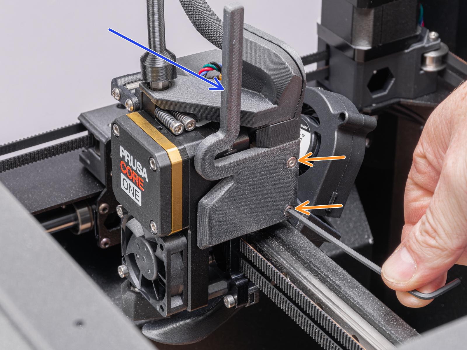
- Place the C1+ PRINTHEAD COVER RIGHT LEVER in place of the Print-head-cover-right and secure it with two M3x6 screws.
Top panel upgrade
In the following steps, we will guide you through installing the part on the top cover grille for its automatic opening.
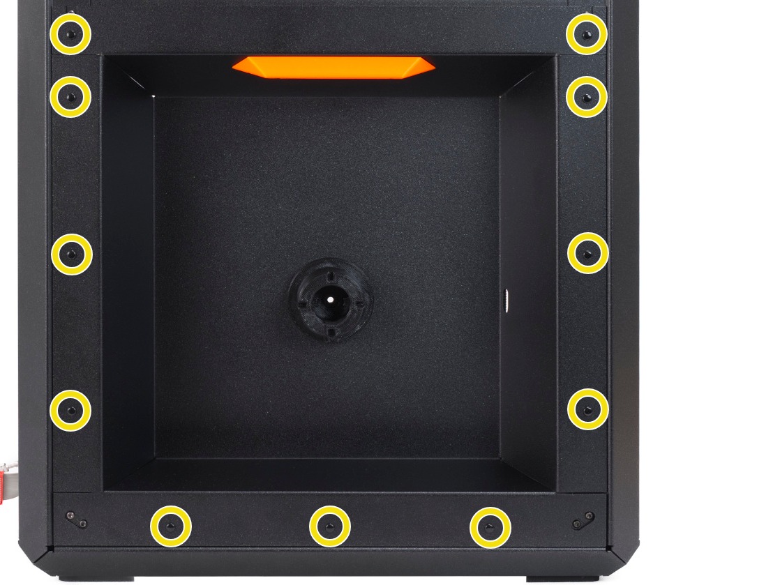
- Place the top panel on the table with the grille facing down.
- Loosen all the screws on the grille and remove them from the assembly.
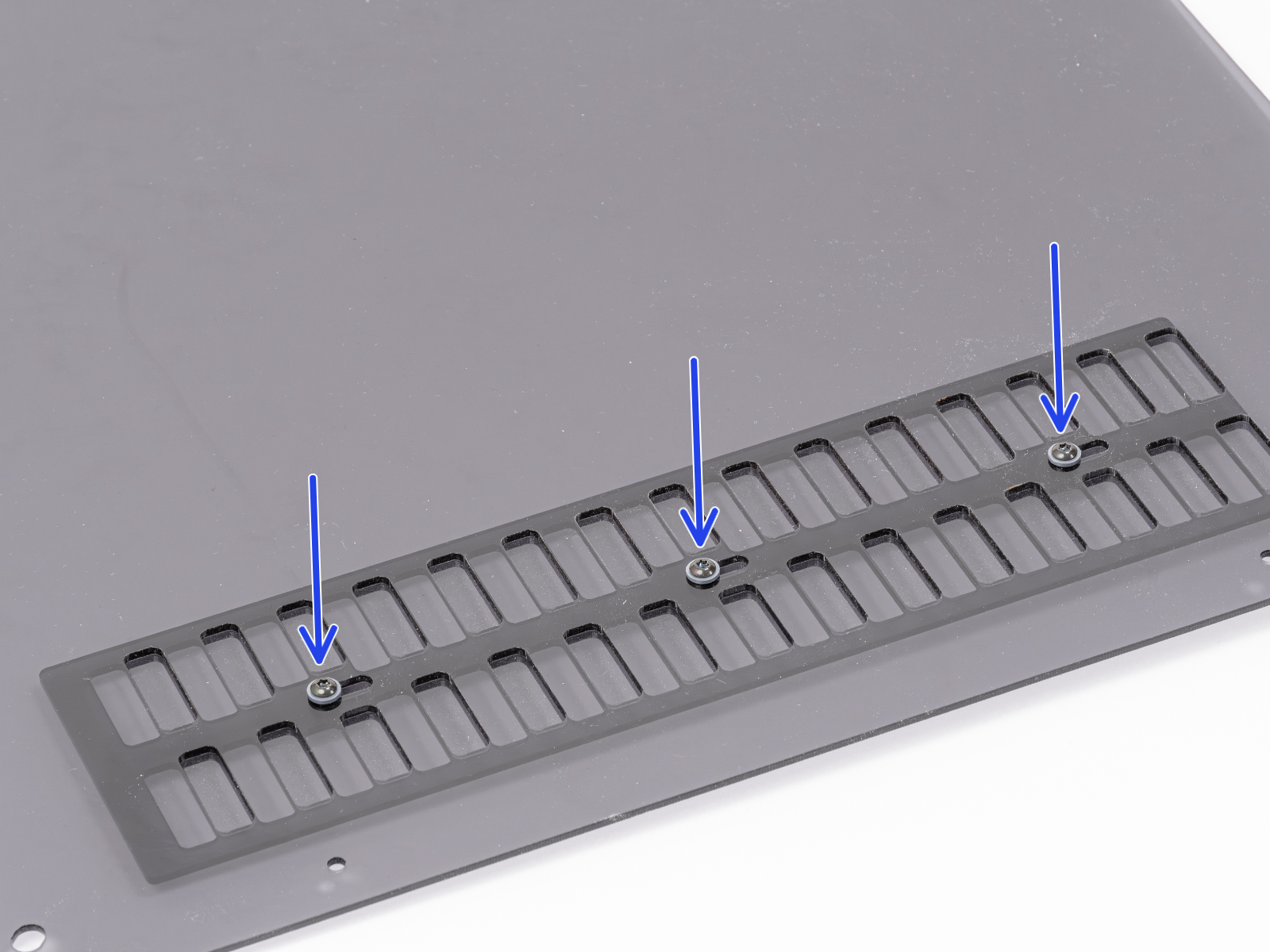
- Carefully slide the grille out from underneath, while keeping both parts aligned.
- Flip the grille 180°.
The screw holes are offset; flipping this moves the holes to the opposite side, ensuring they align with the vent block mounted in the following steps.
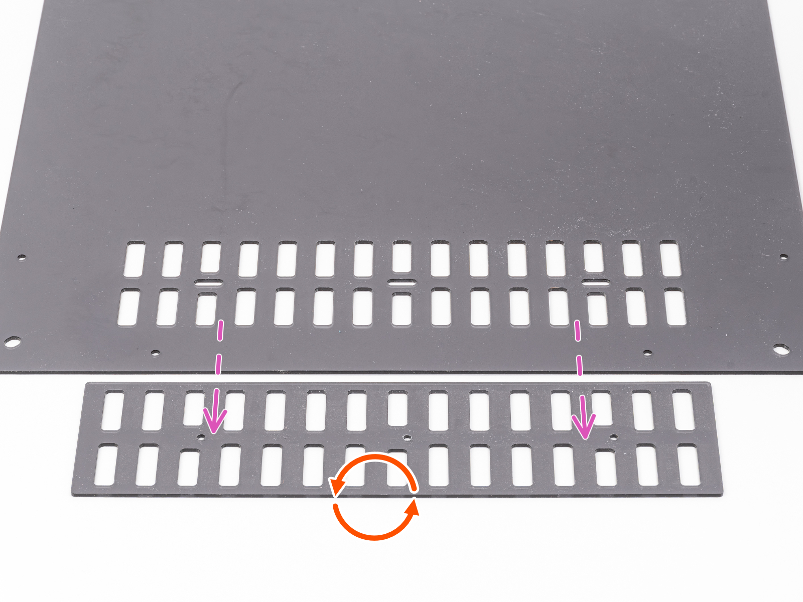
- Flip the grille 180°.
- Slide it back under the top panel in this orientation and align it with the top grille.
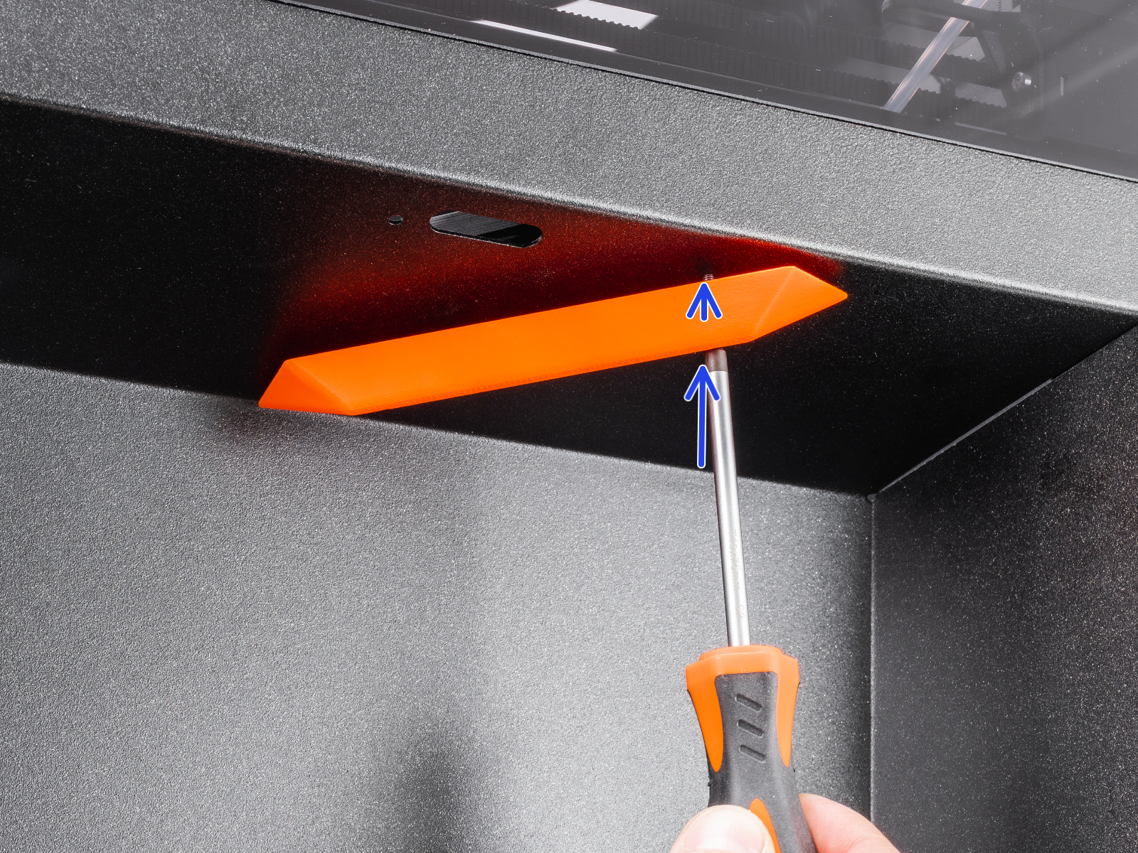
- Insert the three M3x10rT screws with the insulating inserts into the three holes in the top panel.
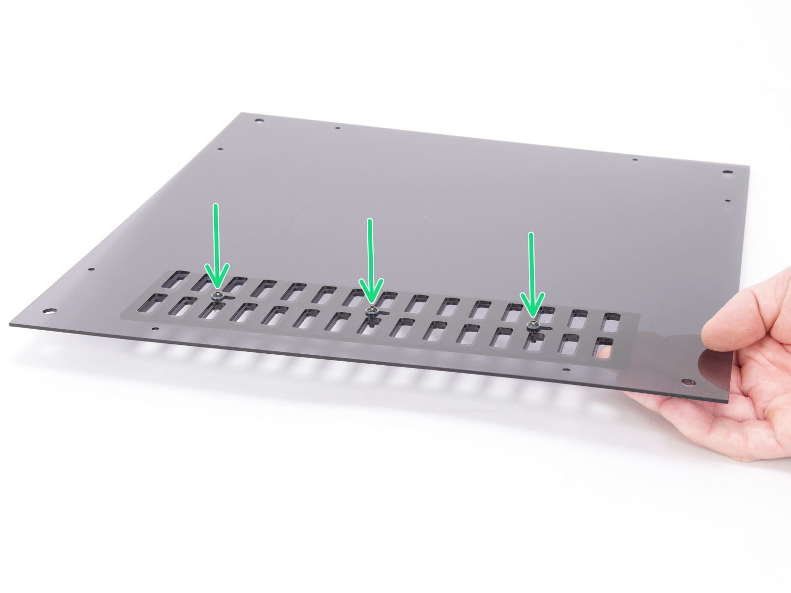
- Carefully lift the entire assembly with all parts positioned in place.
- Place the C1+ UPG VENT BLOCK B onto the screws and tighten them, but not completely.
- Make sure the part is correctly oriented.
- Note: The screw may encounter resistance during tightening, as the part has no thread and the screw cuts its own.
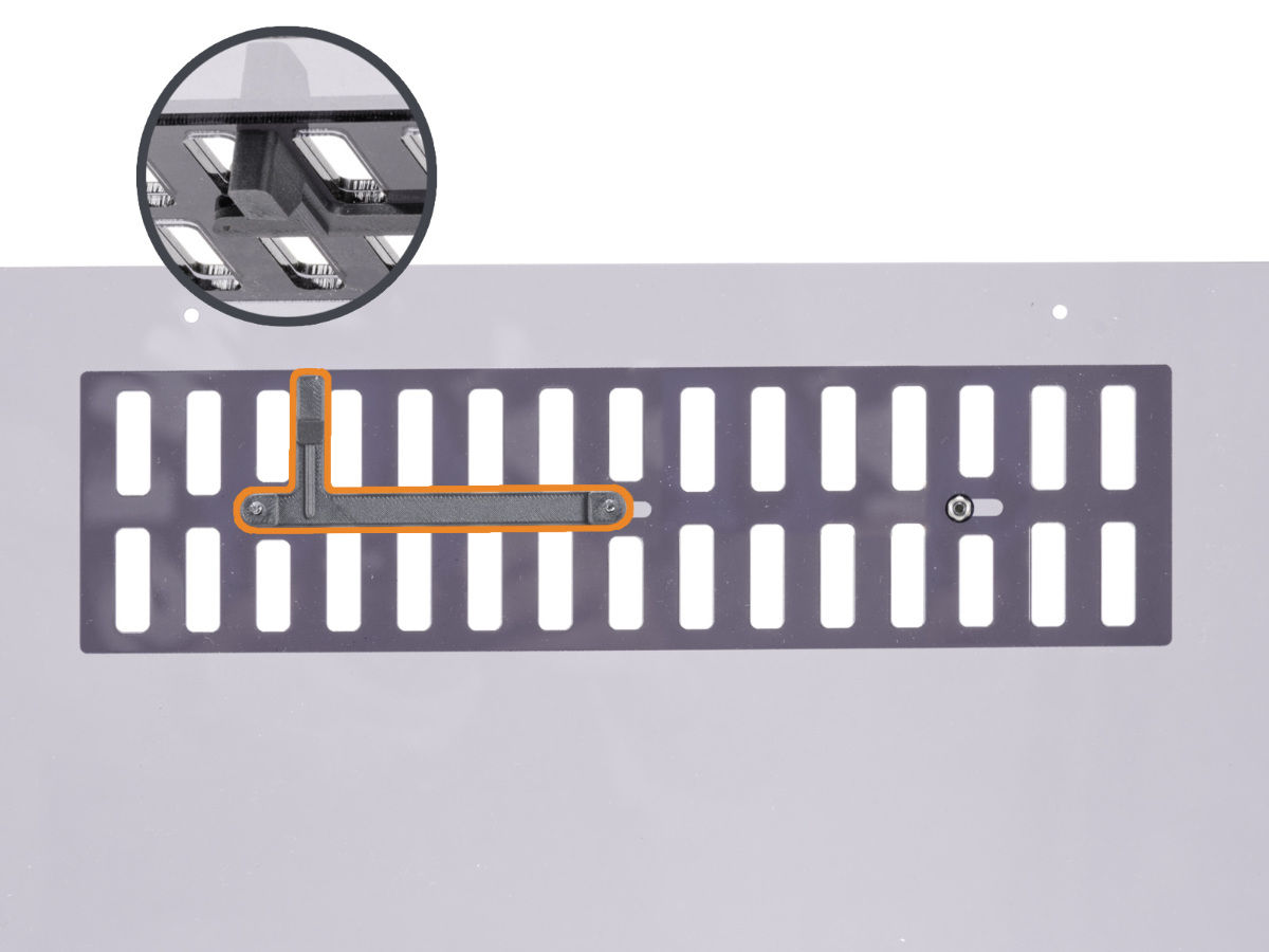
- Screw the M3nN nut onto the screw on the right. Do not tighten it fully; no screw should be tightened completely at this stage, as the grille must remain able to move freely.
- For now, set the panel aside in a safe place.
Side filament sensor & spool holder upgrade
In the following steps, we will guide you through upgrading the filament sensor assembly, which features a completely new body with a mechanical sensor switch. As part of this procedure, you will also upgrade the spool holder to the new design.
- Using steps 1-8 from the How to replace the side filament sensor (CORE One) guide, remove the right side panel and detach the IR filament sensor from the filament sensor assembly.
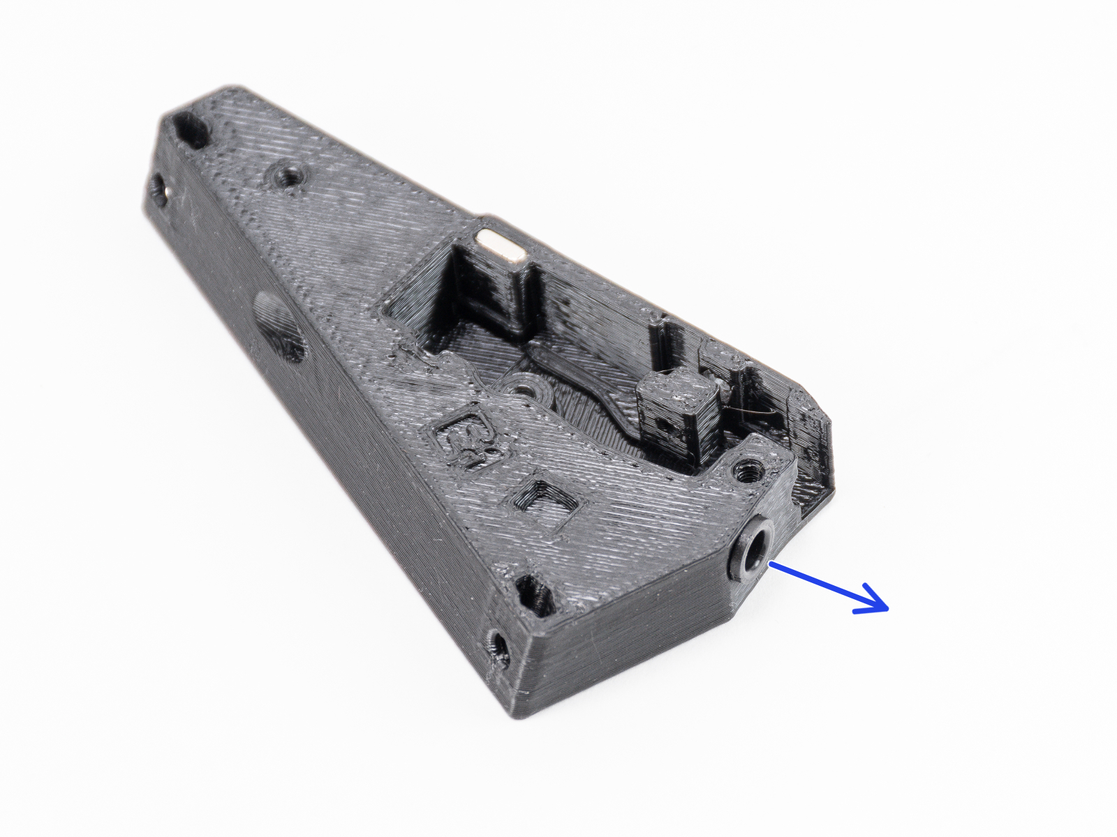
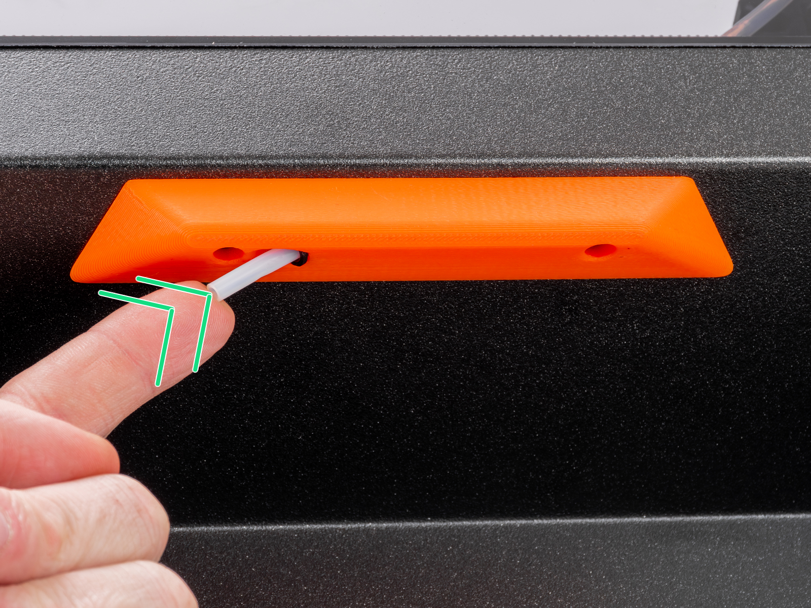
- Press the black collet inward on the filament sensor to release the PTFE tube. Remove the tube while doing pressing the collet.
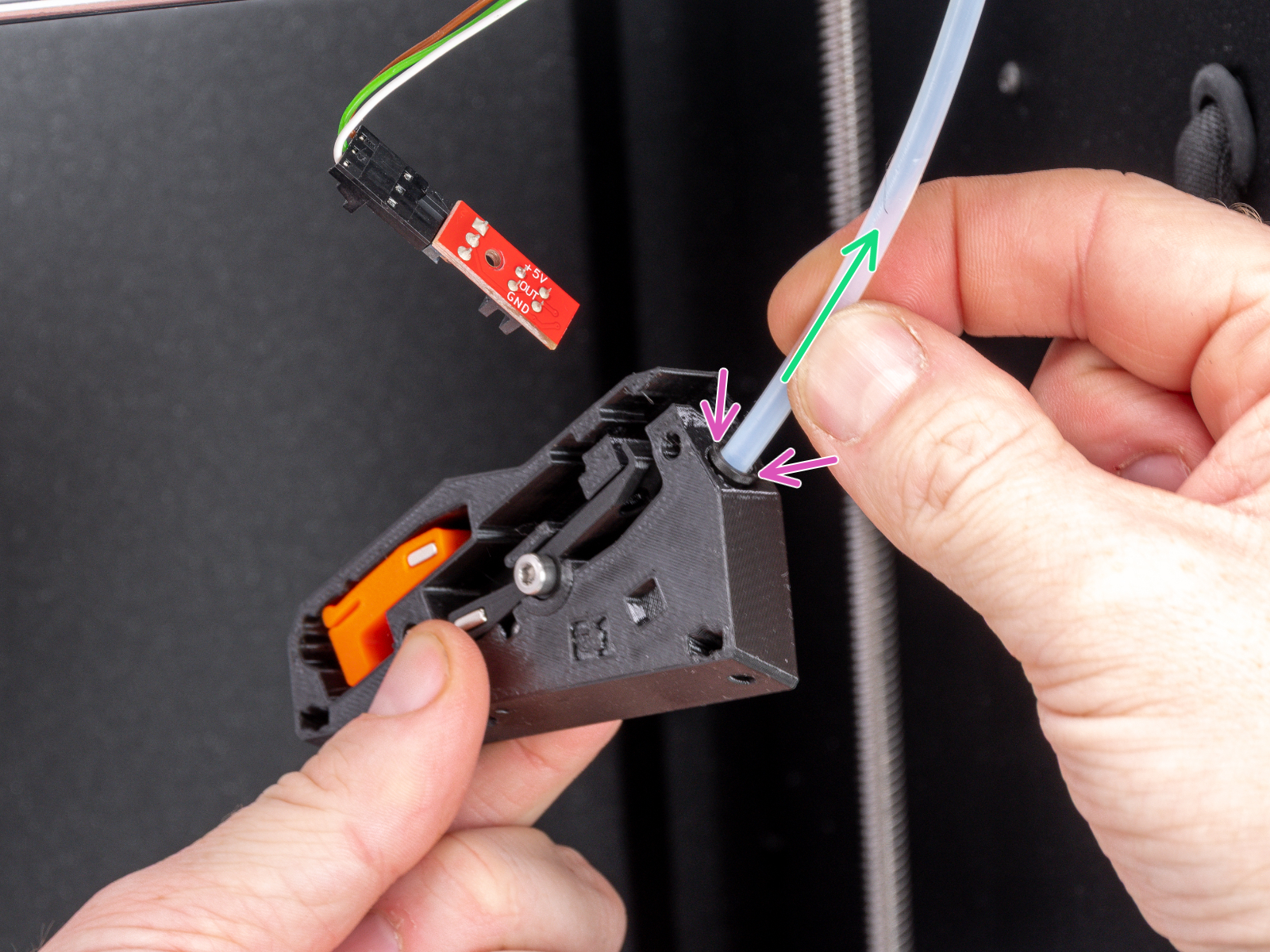
- Take the filament sensor body out of the printer.
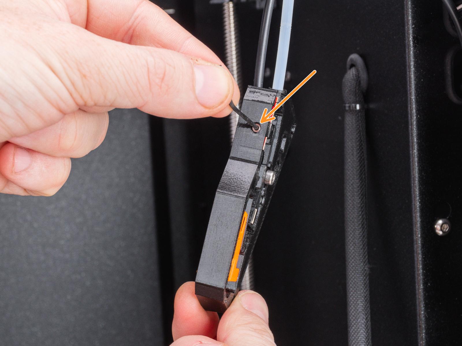
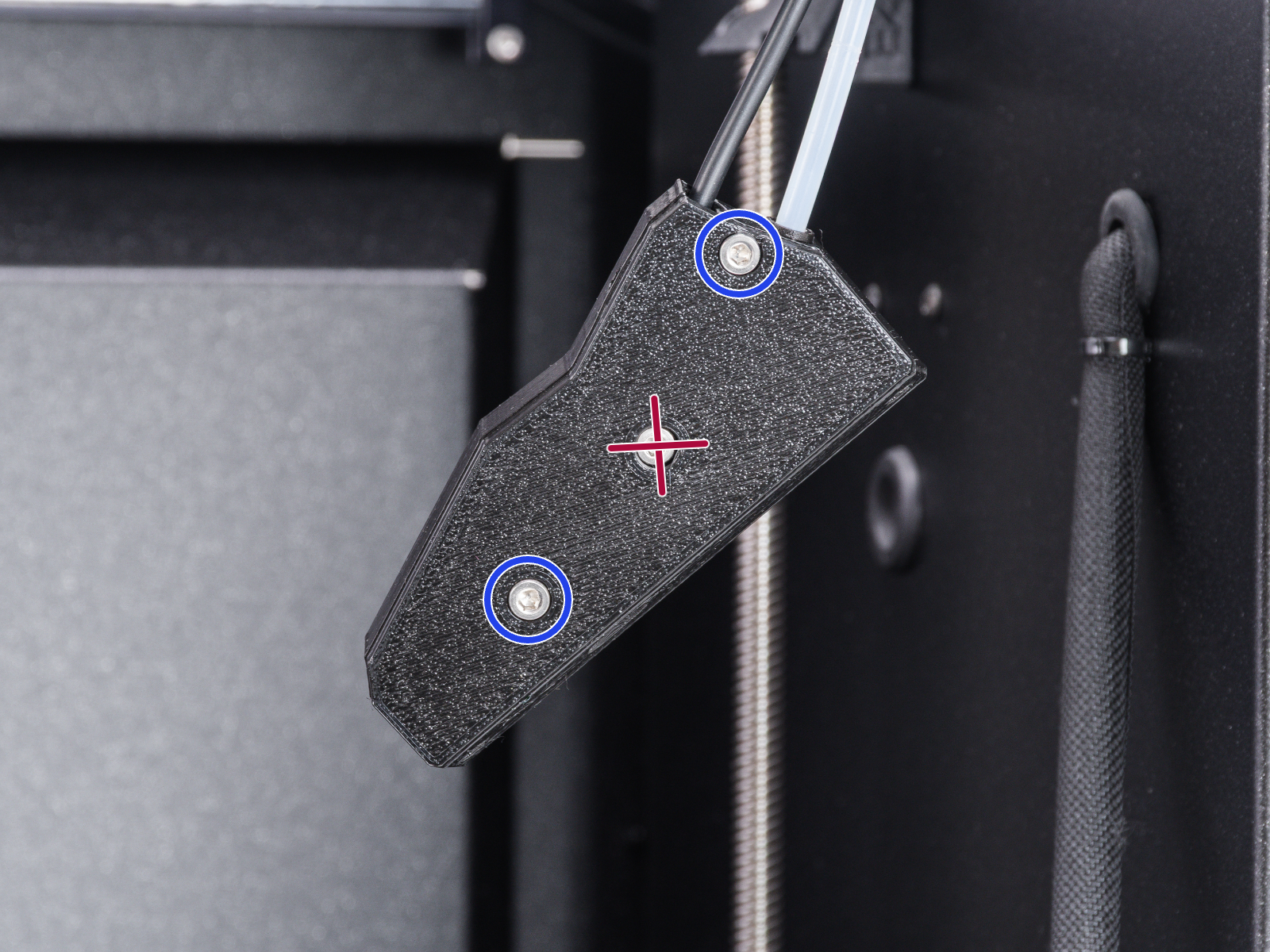
- Release the screw fixing the lever and remove the lever from the body.
- Remove and safely store the steel ball from the filament sensor assembly. You will need it again soon.
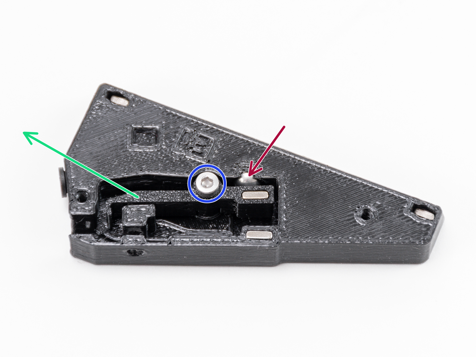
- Remove and safely store the steel ball from the filament sensor assembly. You will need it again soon.
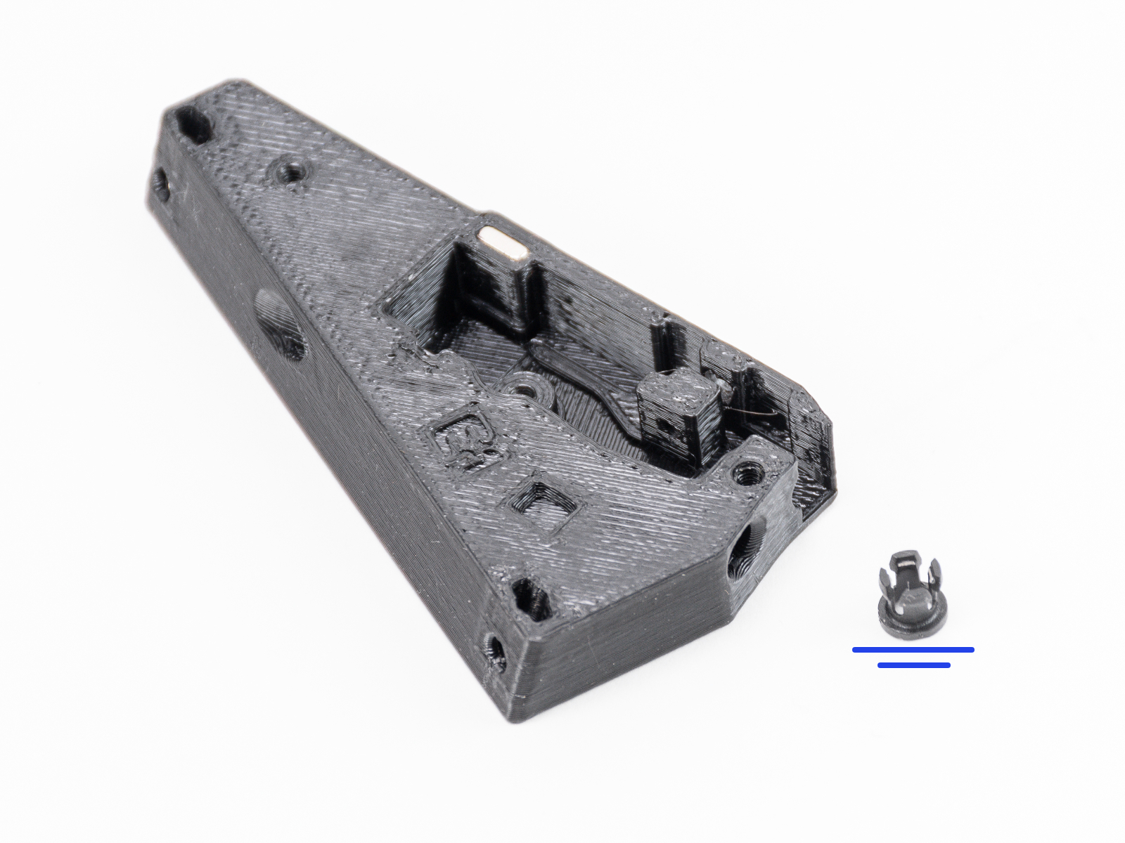
- Pull out the black collet and set it aside in a safe place. You will need it again shortly.
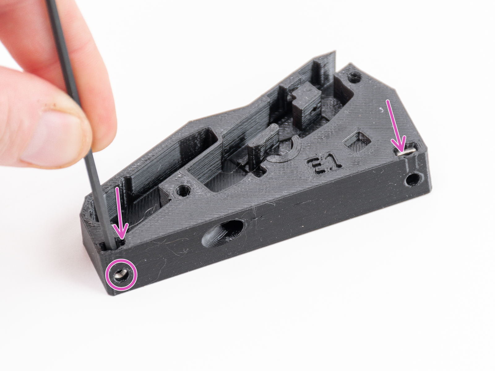
- Now is a good time to try to remove the following parts from the assembly:
- 2x magnet 10x6x2 - from the body and the lever
- 2x M3nS nut - from the body
- Push two M3nS nuts into the new filament sensor body - C1+ FILAMENT SENSOR BODY. Make sure the nuts are fully seated as deeply as possible.
- Press and snap the black collet into the new filament sensor body.
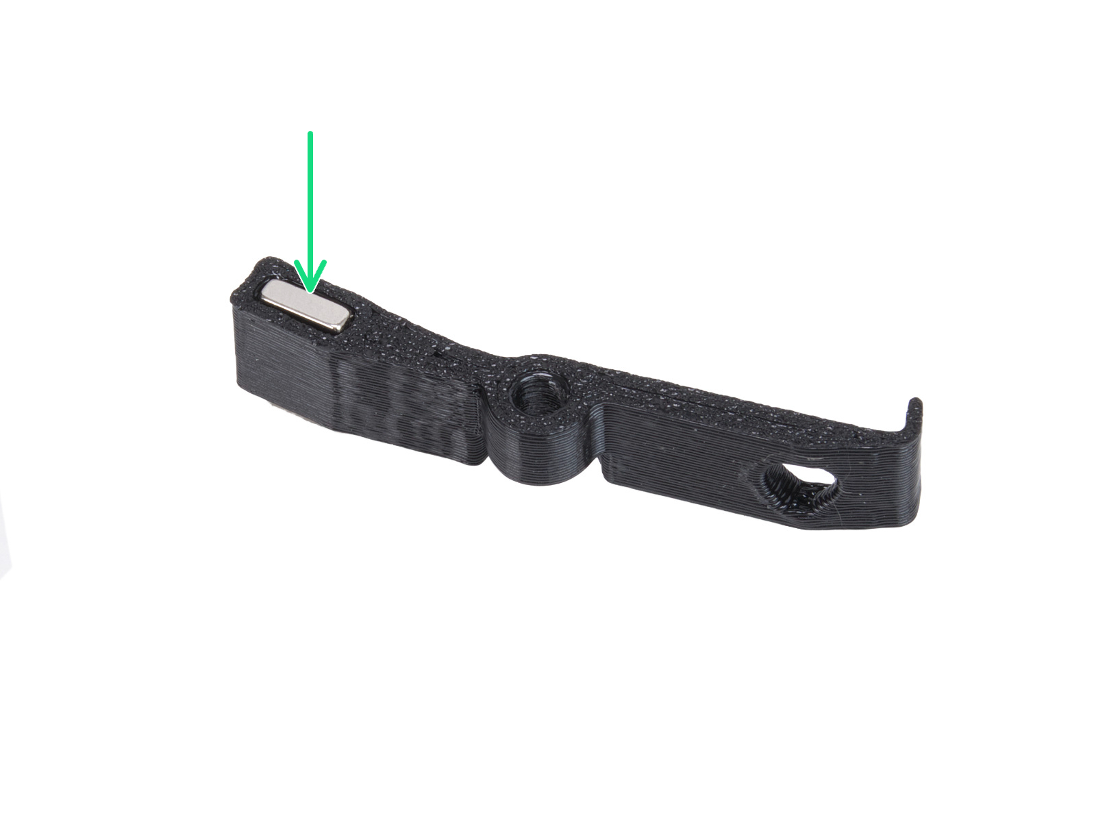
- Insert one 10x6x2 magnet into the new lever - C1+ FILAMENT SENSOR LEVER.
- Insert the steel ball and then the new lever into the filament sensor body, and secure the lever with the M3x10 screw. Do not overtighten the screw; the lever must move freely.
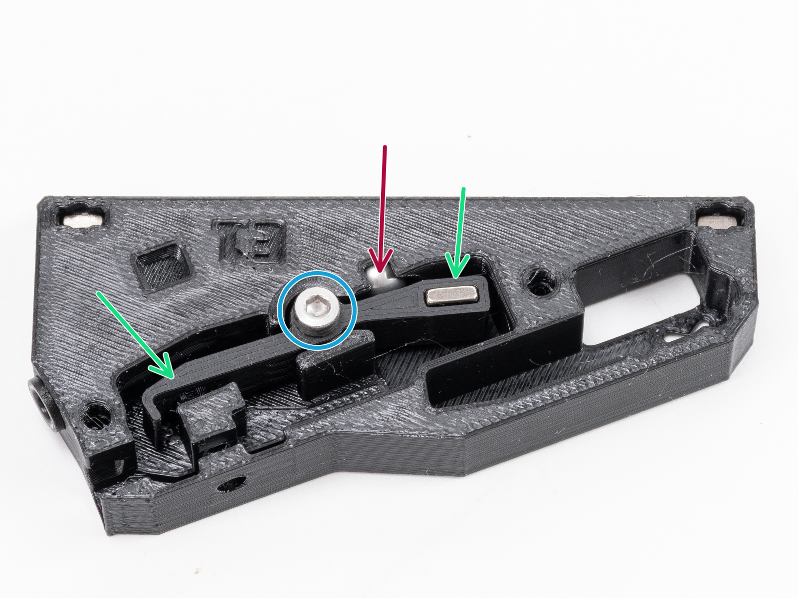
- Insert the second 10x6x2 magnet into the C1+ FILAMENT SENSOR SWITCH. The magnet must be positioned so that it repels the magnet in the lever.
- Insert the switch into the assembly and test it. If the magnets attract each other, simply press the magnetout of the switch and flip it.
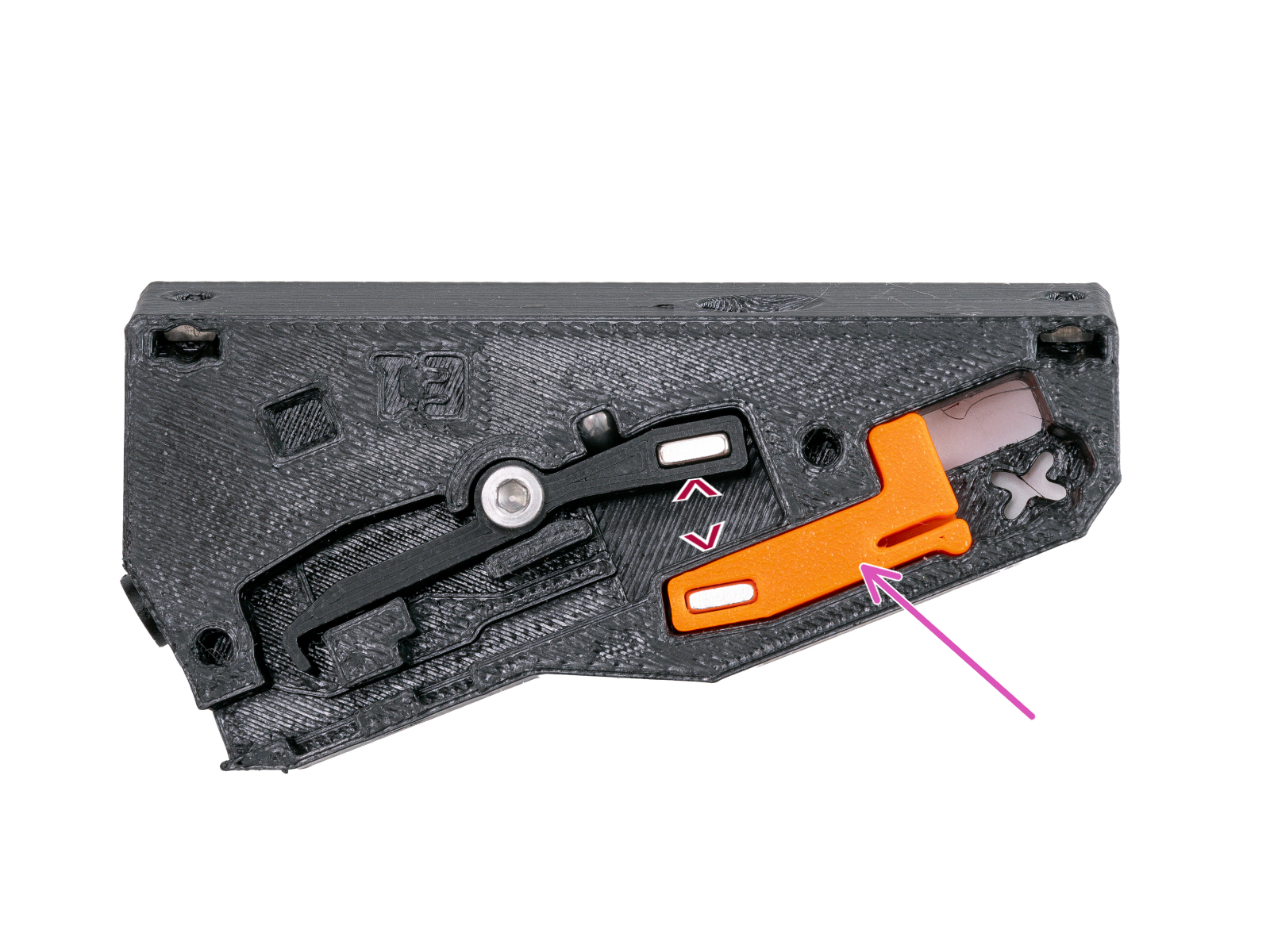
- Insert the switch into the assembly and test it. If the magnets attract each other, simply press the magnetout of the switch and flip it.
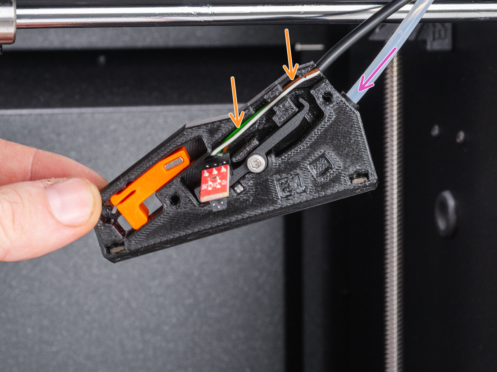
- On the printer, insert the PTFE tube as far as possible into the new filament sensor body.
- Insert the IR filament sensor cable into the groove. The black connector should be approximately in the middle of the sensor base.
- Insert the IR sensor itself into the dedicated groove.
- The lever must fit into the optical gate part of the sensor.
- Make sure neither the connector nor the cables touch the lever or the switch, as this could prevent the sensor from functioning correctly.
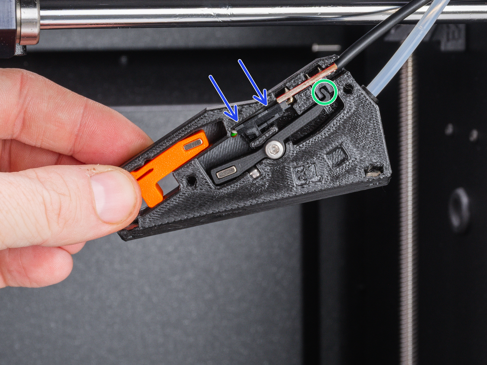
- Using the 1.5mm Allen key, fix the sensor in place with the M2x8 screw.
- Before covering the filament sensor, toggle the switch a few times and leave to test it and then turn it ON (observe the X symbol).
- Place the C1+ FILAMENT SENSOR COVER on the body and secure it with two M3x8 screws.
- Do not tighten the screw in the middle! Otherwise, the sensor would stop working.
- Do not tighten the screw in the middle! Otherwise, the sensor would stop working.
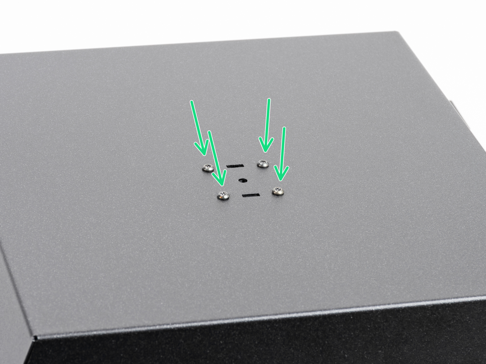
- Prepare the right side panel and remove four screws securing the spool holder. Then, remove the spool holder.
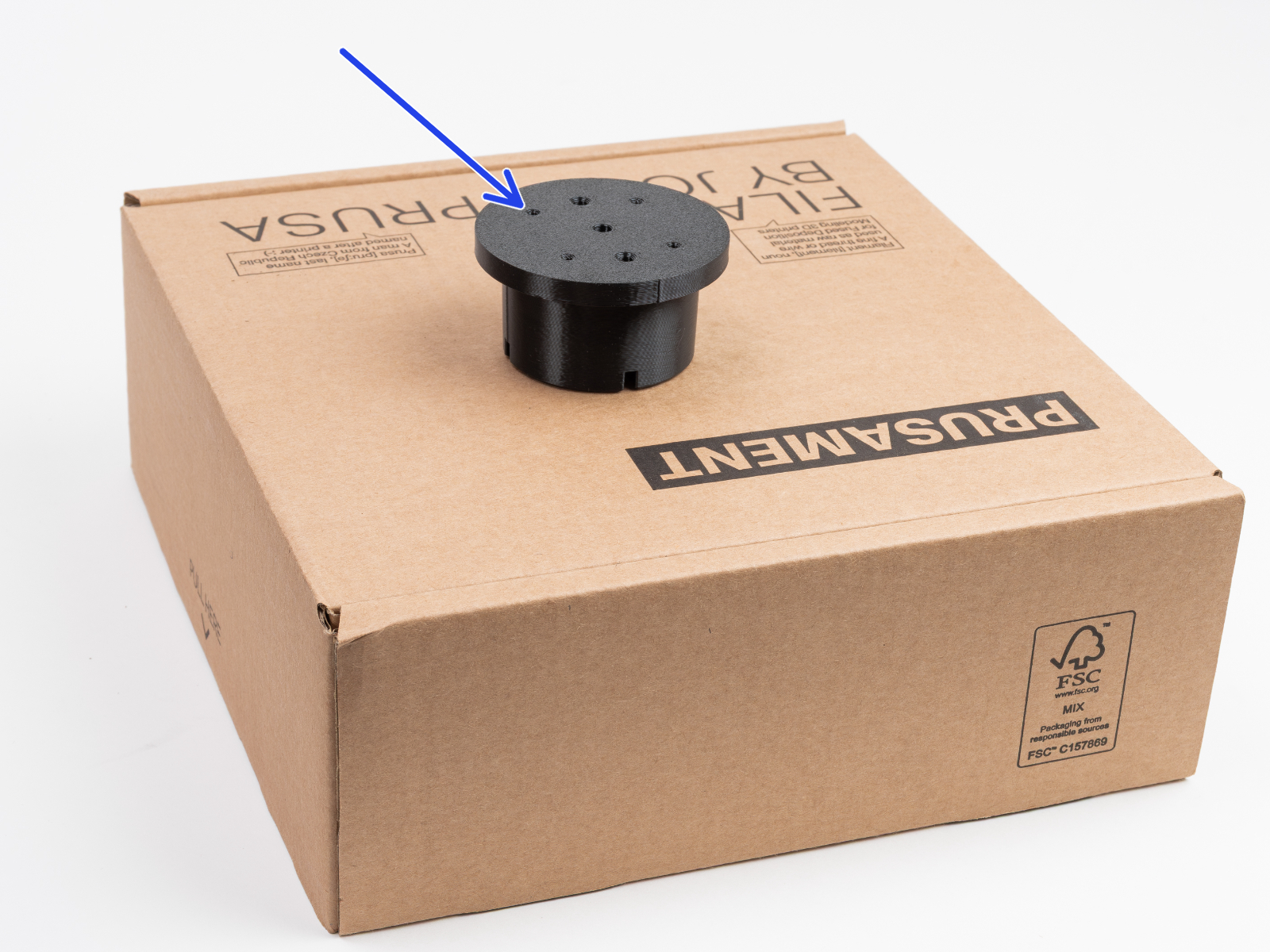
- Put the PUCK UNIVERSAL with the screw holes pointing upward on the filament box.
- Place the right side panel on the PUCK UNIVERSAL and line up four holes in both parts.
- Fix the PUCK UNIVERSAL to the panel using four M3x10rT. Tighten them firmly.
- Place the right side panel back to the printer and secure it with eleven nylon rivets. Re-use the old ones.
- Take the handle and pull the PTFE tube out of it.
- Push one M3x10rT screw through the right hole in the handle.
- Place the handle to the side panel and push the screw through the hole into the printer.
- From inside the printer, align the filament sensor assembly onto the protruding M3x10rT screw and tighten it.
- Using the same procedure, insert and tighten the second M3x10rT screw.
 |  |
- Push the PTFE tube through the collet in the handle all the way into the filament sensor.
- Place the O-ring 25x3.5 mm on the SPOOLHOLDER STATIC.
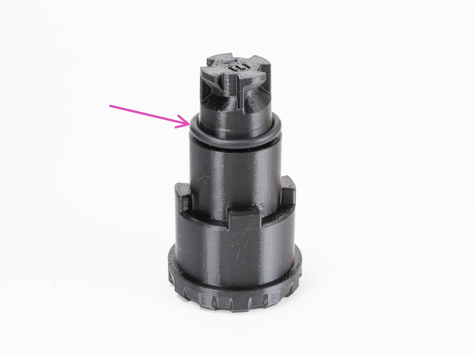
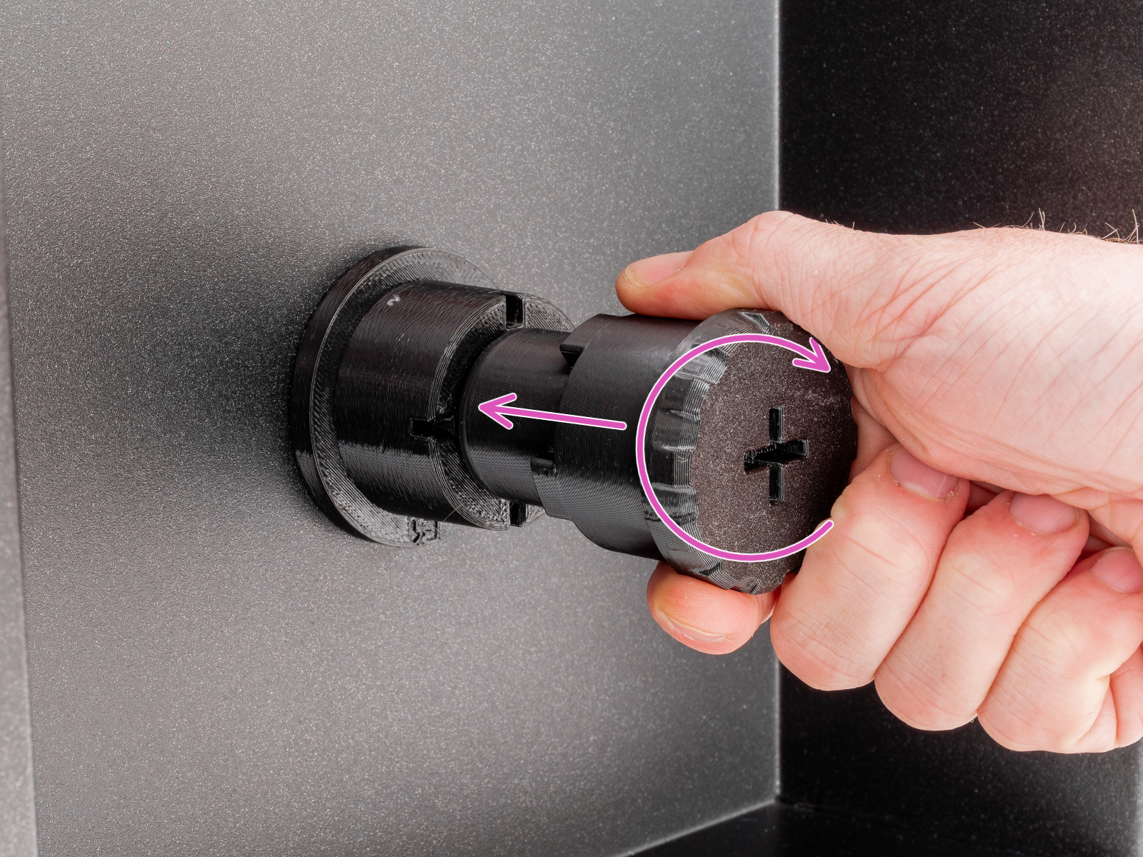
- Mount the SPOOLHOLDER STATIC onto the PUCK UNIVERSAL and twist it clockwise to lock it in place.
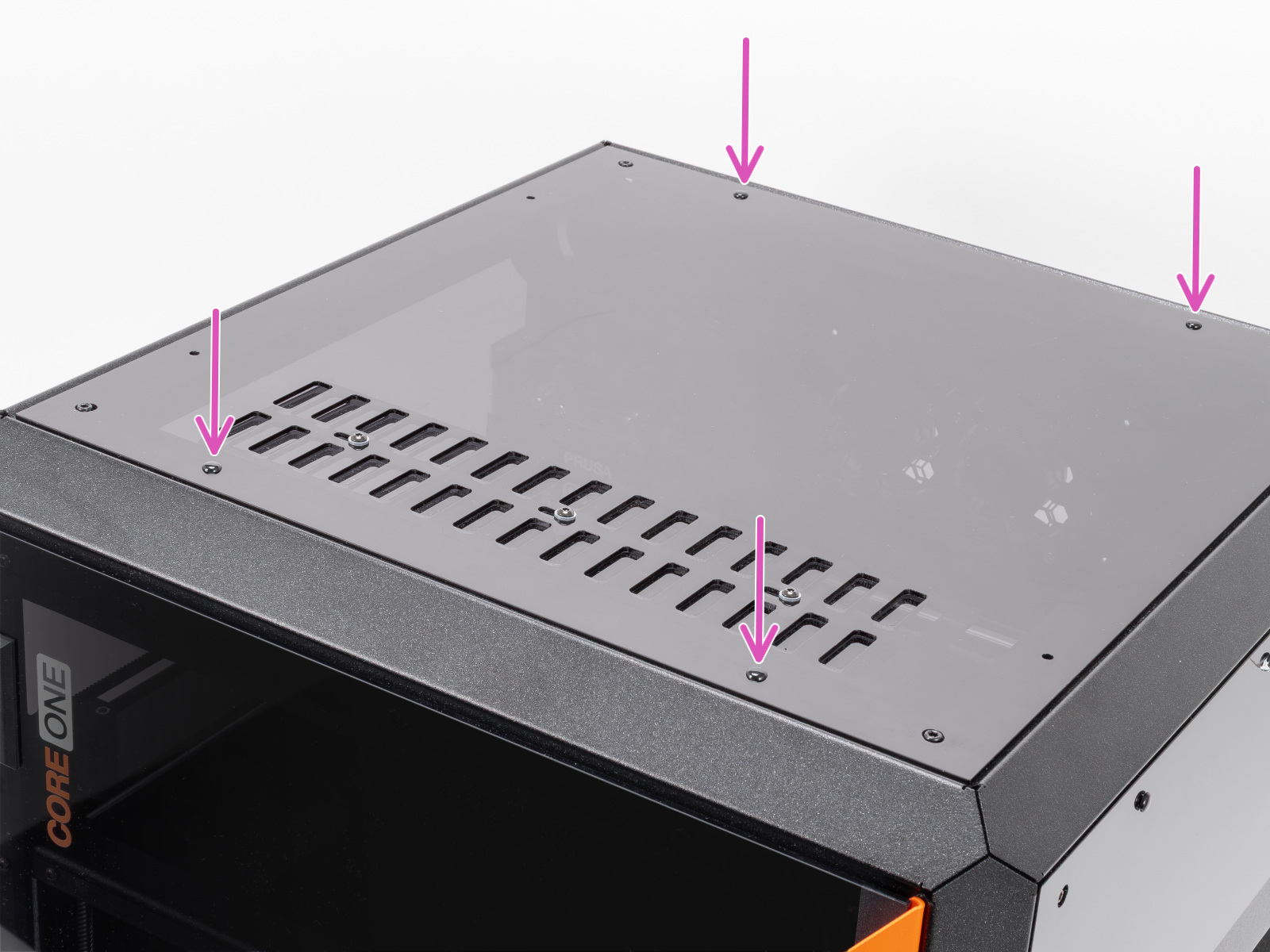
- And finally, install the upgraded top panel back to the printer. Secure it with the nylon rivets.
First run
After completing the upgrade, we recommend performing a self-test and recalibrating the filament sensor. Make sure the mechanical filament sensor switch is in the ON position (switcher is up).
To enable automatic opening of the top grille, go to Settings -> Hardware -> Chamber Vent Control and set to Auto.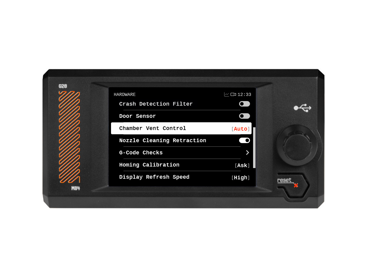
41 comments
Or am i missing something?
My sensor lever is apparently slightly jammed after first assambly attempt...
One I spotted is the C1+ UPG VENT BLOCK B in the community version, and Upg-vent-block in the official version.
The community version re-uses two M3x10rT screws to mount it, while the official one is mounted with two M3x12rT screws plus two nuts, supplied in the official kit.