Relevant for


If you received your Prusa CORE One INDX conversion kit with the Prusa CORE One+ Gen 2 upgrade, or bought the Gen 2 upgrade separately and want to install both at the same time, this article will help you with the process. Read the instructions and information in this article thoroughly.
If you received the CORE One+ GEN 2 upgrade as part of your Prusa INDX conversion kit, note that all the GEN 2 upgrade parts are included in the UPGRADE box.
Follow the Prusa INDX guide from the start.
Keep following the instructions in the Prusa INDX guide until you finish step SECURING THE BED SPACER - RIGHT, then read the instructions below in this article:
Before you move on to the next step in the Prusa INDX guide, we need to disconnect the X and Y motor cables and remove the left side panel and cover from the printer to accommodate the GEN 2 upgrades.
Follow the instructions below:
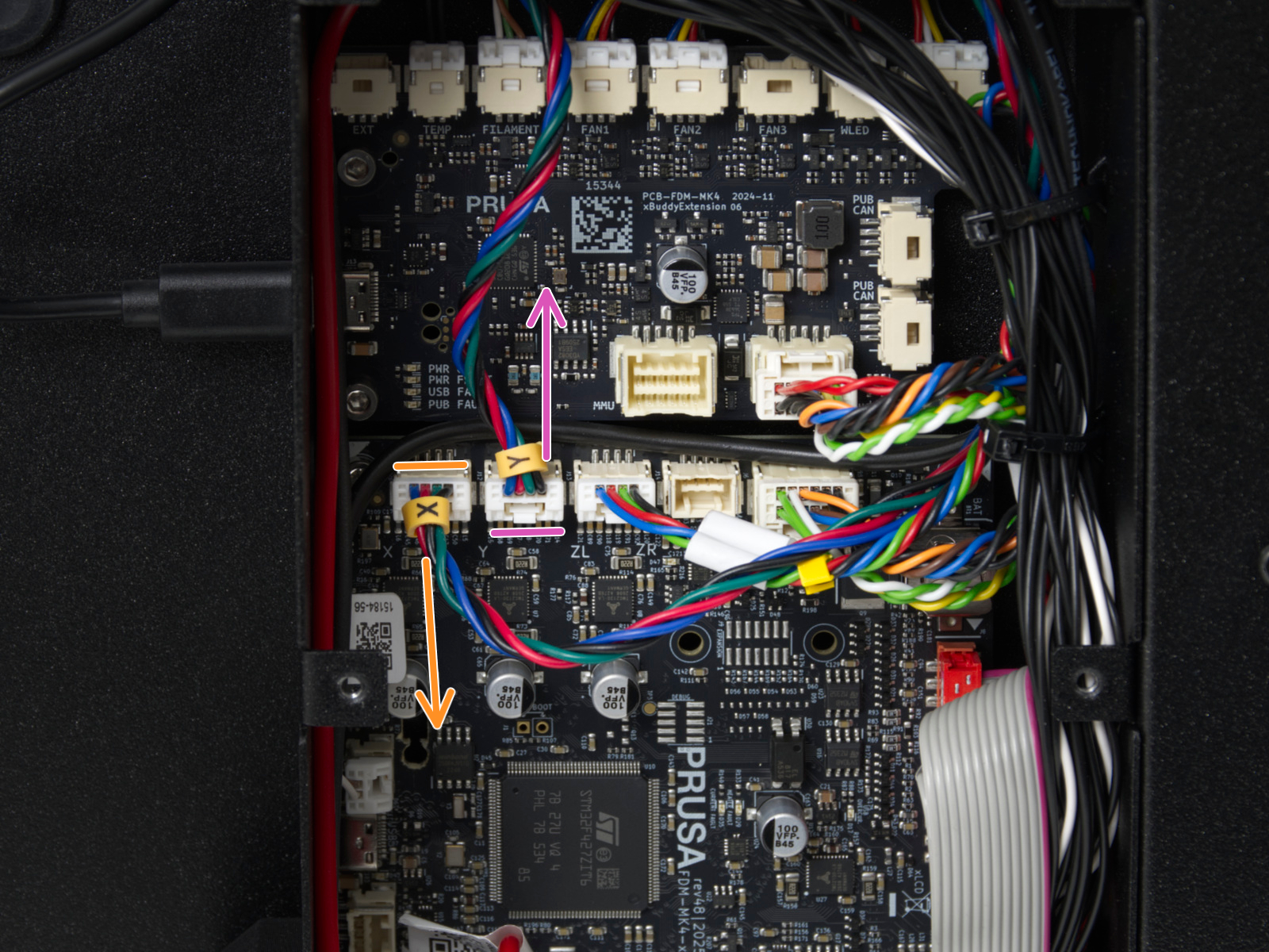
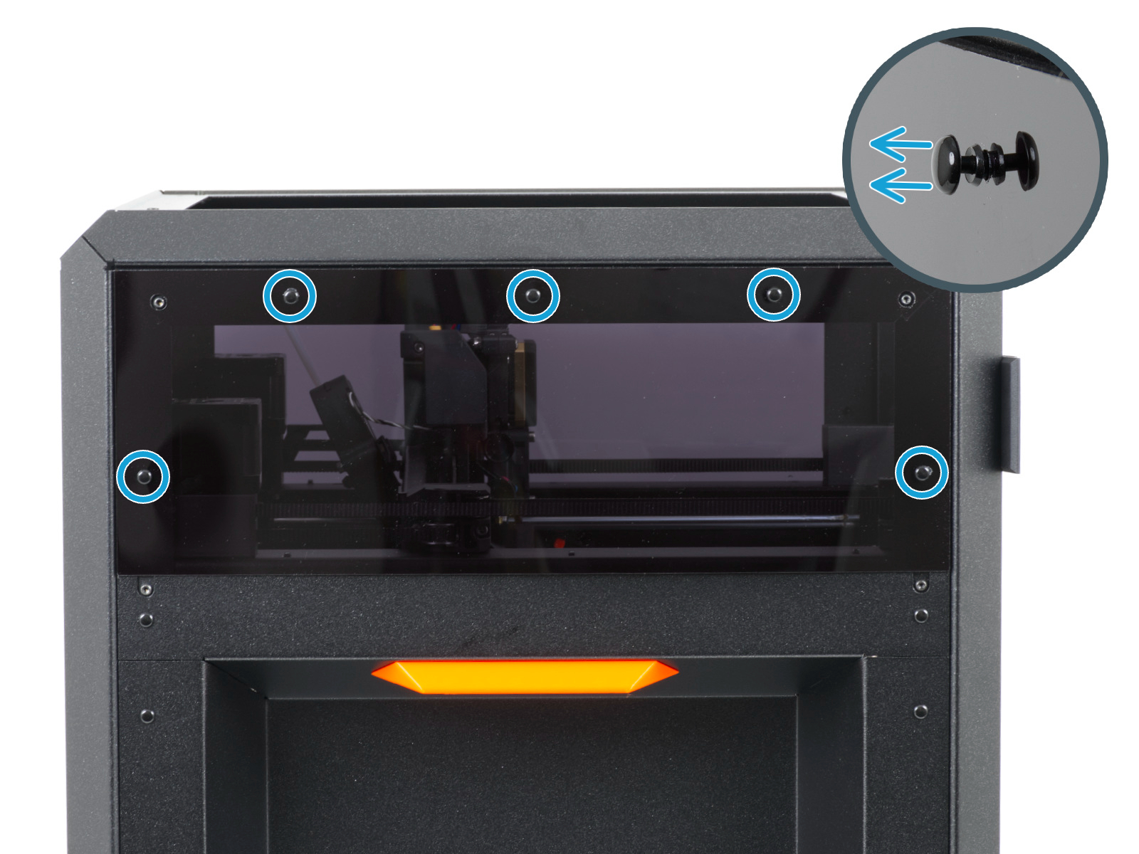 | 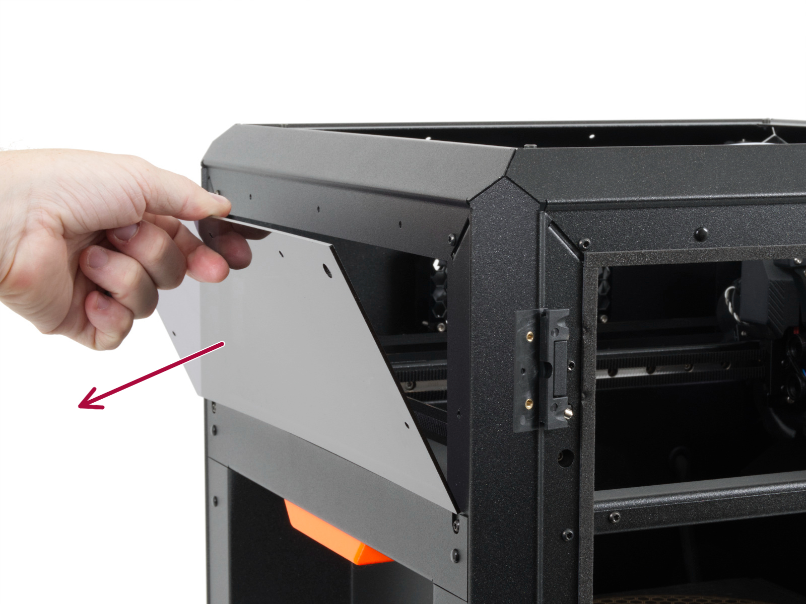 |
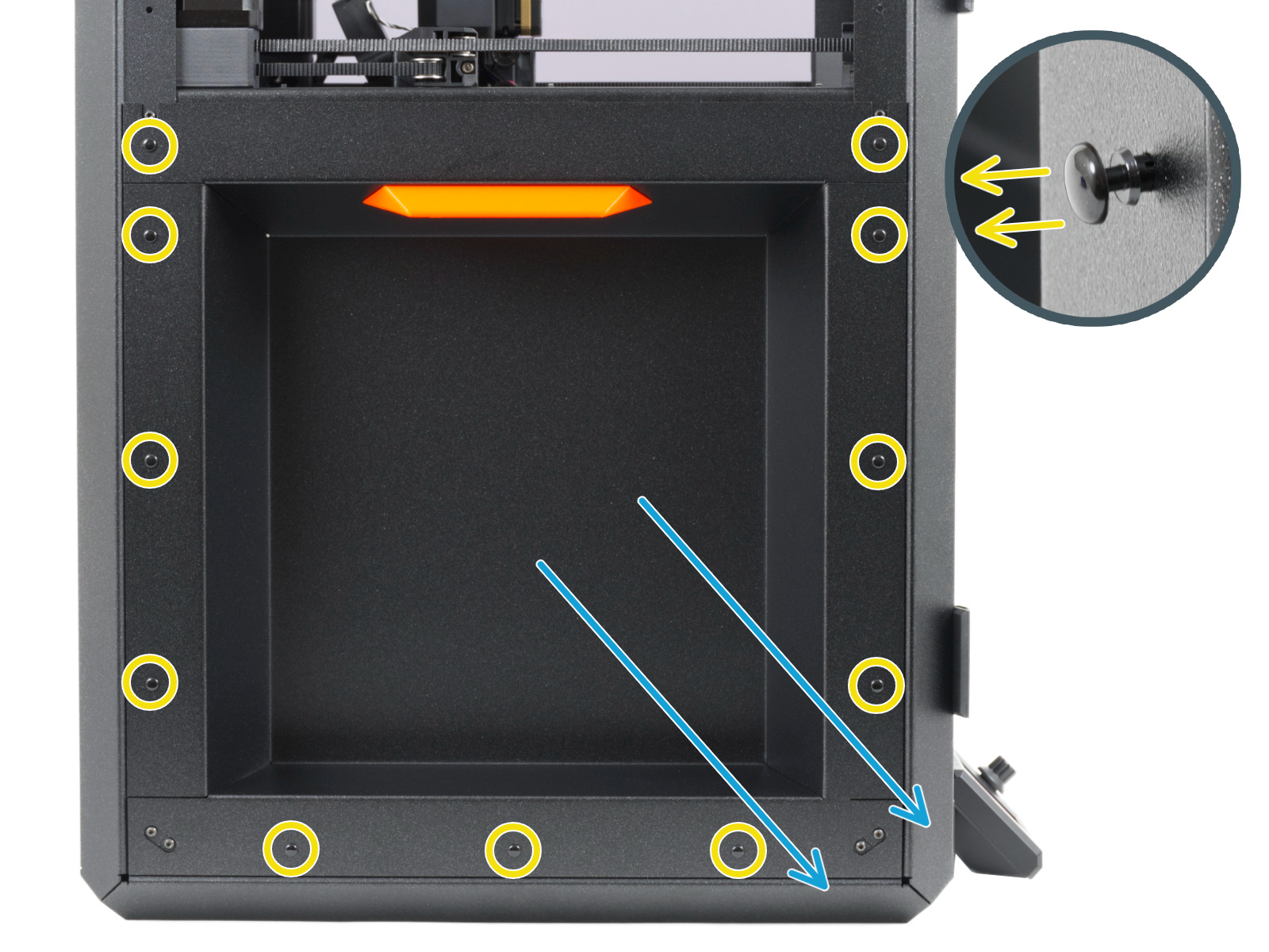
Once the motors are unplugged and the left panel and cover are removed, return to the Prusa INDX guide step REMOVING THE REAR BED SPACER, and continue from there.
Keep following the instructions in the Prusa INDX guide until you finish step SECURING THE OFFSET SENSOR CABLE.
Switch to the GEN 2 guide, step REMOVING OLD EXPANSION JOINTS, and continue from there.
Keep following the instructions in the GEN 2 guide until you finish step INSERTING THE HEATBED SPACER.
Return to the Prusa INDX guide, step REMOVING THE BED-CABLE-COVER-BOTTOM, and continue from there.
Keep following the instructions in the Prusa INDX guide all the way until you finish step RELEASING THE BELTS, then read the instructions below in this article:
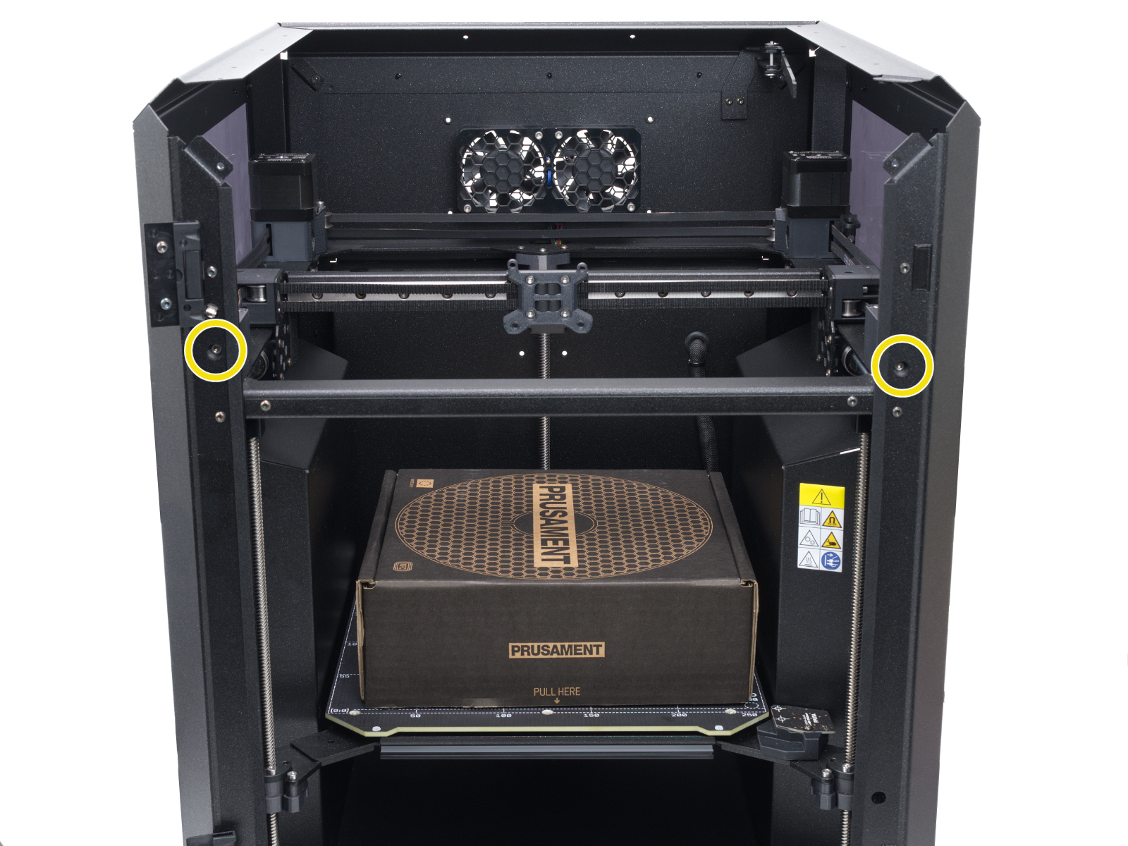
Before you move on to the next step, we need to remove the right side panel and side cover from the printer to implement the GEN 2 upgrades.
Follow the instructions below:
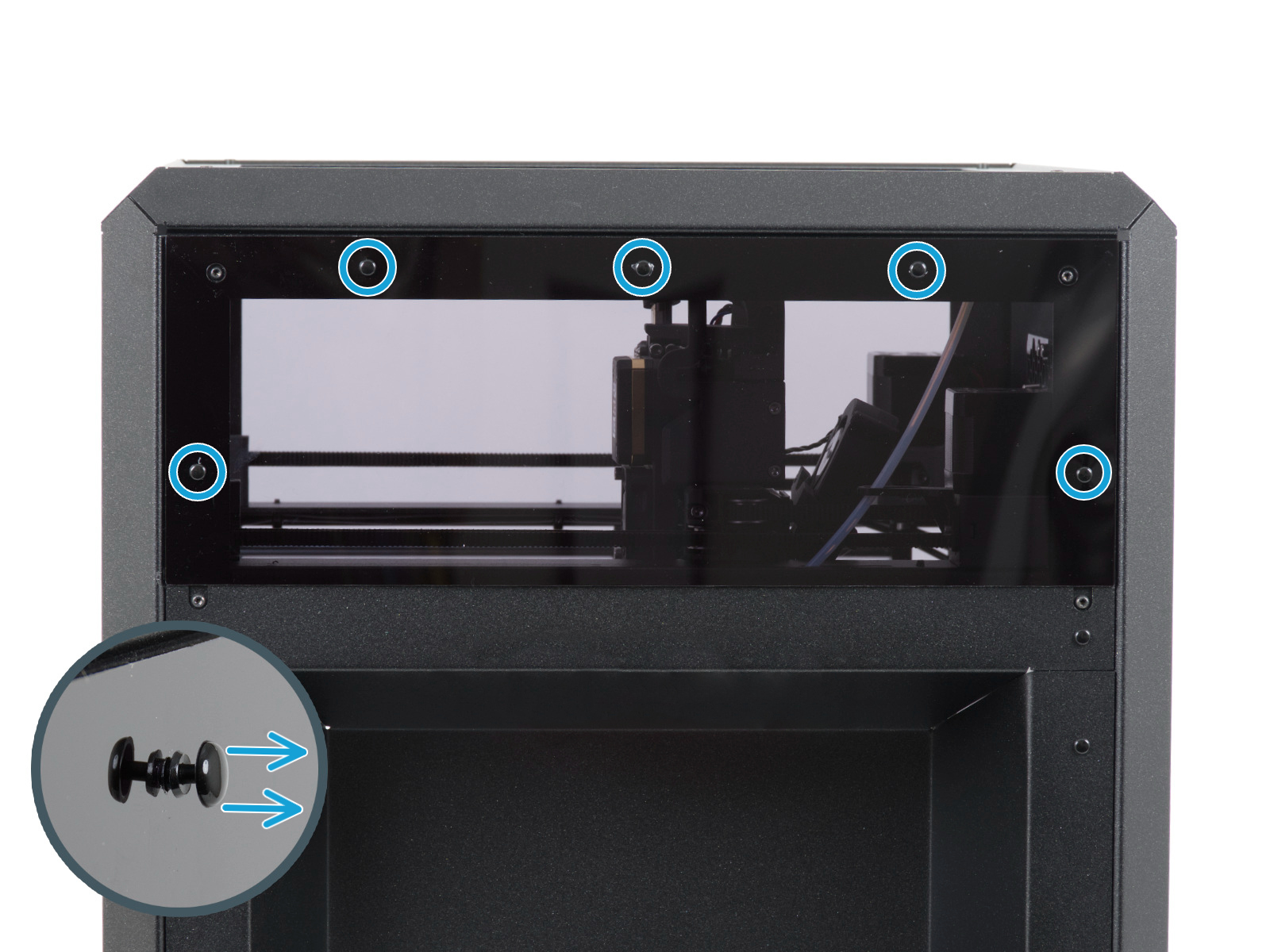 | 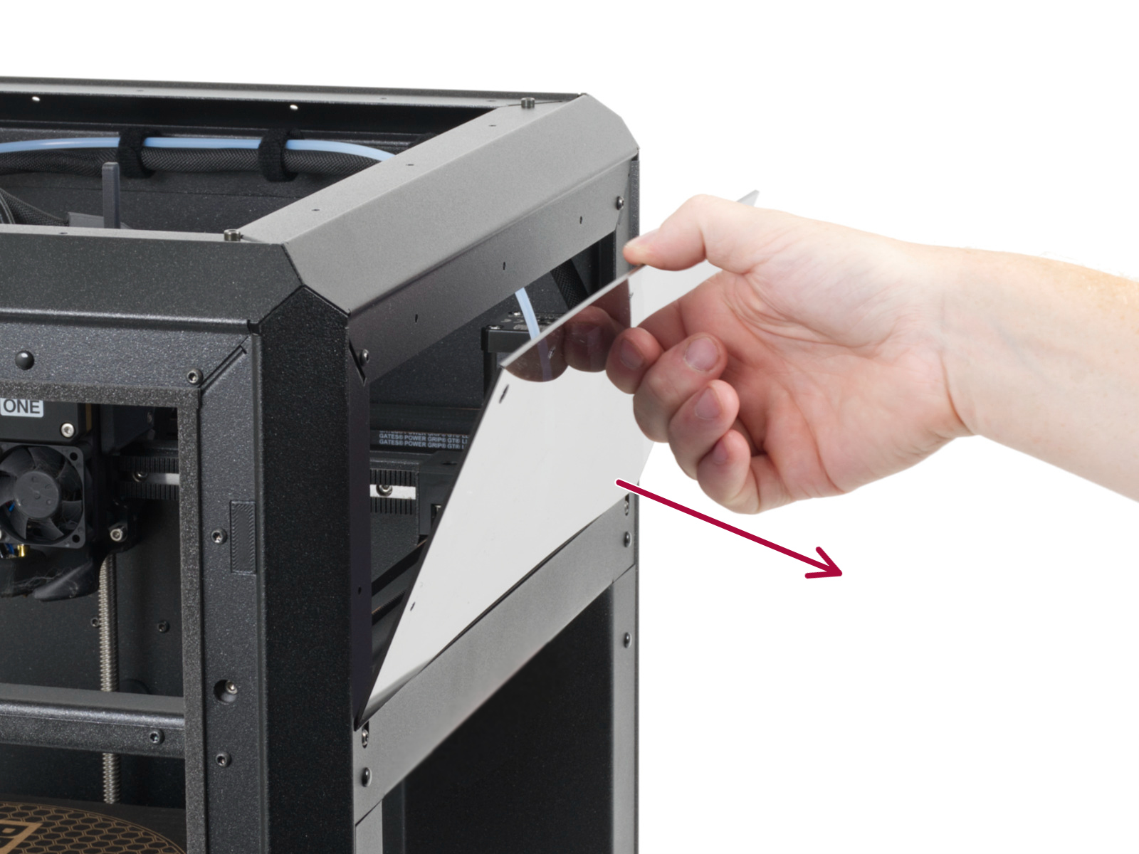 |
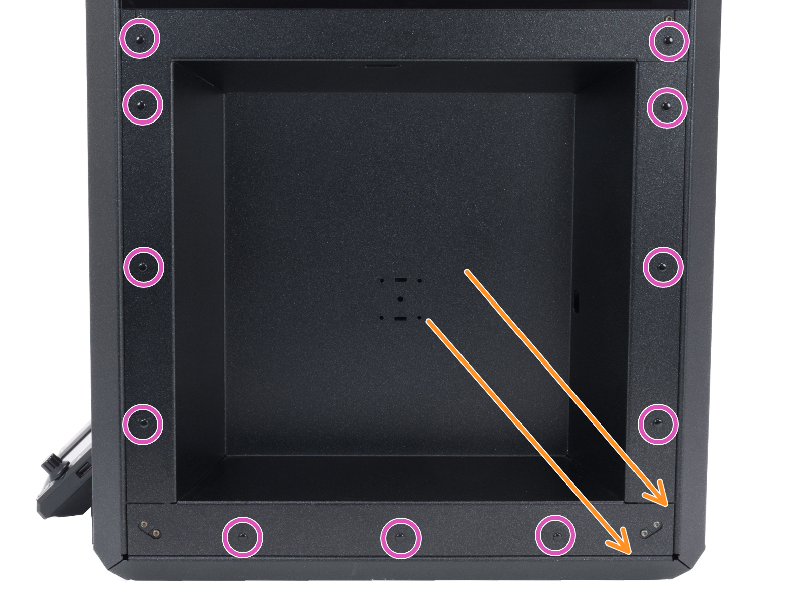
With the right side panel and cover removed, read the information and instructions below in this article before proceeding:
The PTFE tube leading to the filament sensor is removed in the Prusa INDX guide, but is visible in the GEN 2. guide.
The Bowden-guide is visible in the photos. It is also attached back onto the motor assembly in the GEN 2 guide. We will not need it for the Prusa CORE One INDX conversion process; you can remove it from the printer once it is detached from the motor mount.
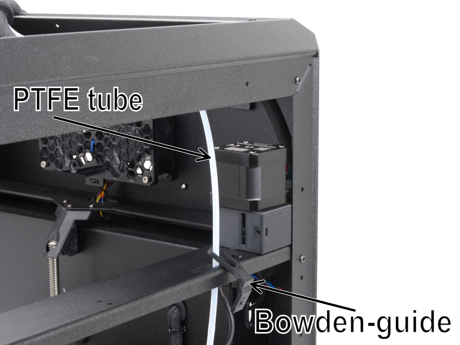
Belt-tensioner screws:
During the upcoming belt exchange instructions in the GEN 2 guide, we recommend using the Prusa lubricant found in the Fasteners 2/2 bag in the Prusa CORE One/+ INDX conversion kit.
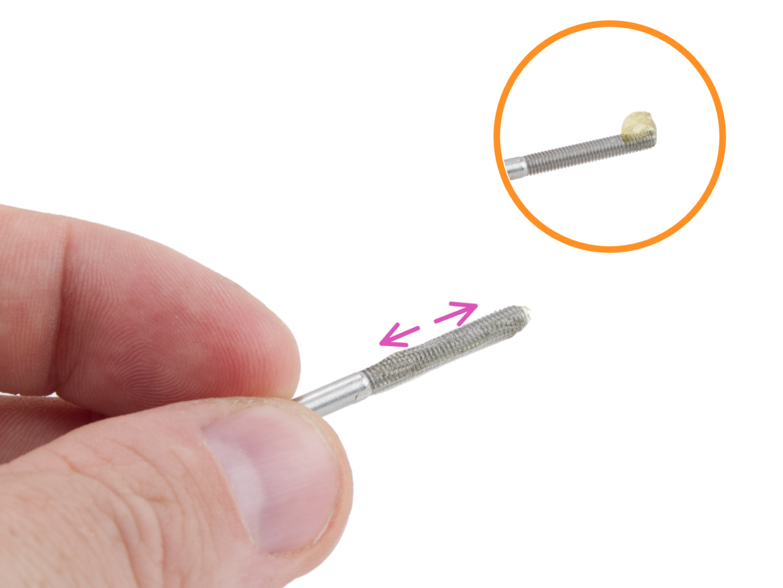
Switch to the GEN 2 guide step REMOVING THE BELTS, and continue from there.
Keep following the instructions in the GEN 2 guide until you finish step GUIDING THE UPPER BELT (GANTRY-RIGHT).
Return to the Prusa INDX guide step GANTRY ALIGNER TOOL: PARTS PREPARATION, and continue from there.
Keep following the instructions in the Prusa INDX guide all the way until you finish step COVERING THE FS - RIGHT.
Before you move on to the next step in the Prusa INDX guide, we need to attach both of the top see-through side panels.
Follow the instructions below:
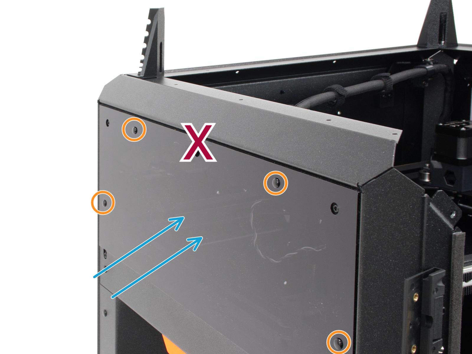
With both top see-through covers mounted back, continue following the Prusa INDX guide step PTFE TUBES - LEFT SIDE: PARTS PREPARATION, and continue from there.
Keep following the instructions in the Prusa INDX guide until you finish step SECURING THE ZIP TIES II.
Switch to the GEN 2 guide step: EXPANSION JOINT ALIGNER, and continue from there.
Keep following the instructions in the GEN 2 guide until you finish step FIXING THE HEATBED.
Now that the expansion joints are aligned, let's return to the step we skipped in the Prusa INDX guide and secure the offset sensor assembly by tightening the M3x10 screw.
The screw forms its own thread in the plastic. Do not overtighten.
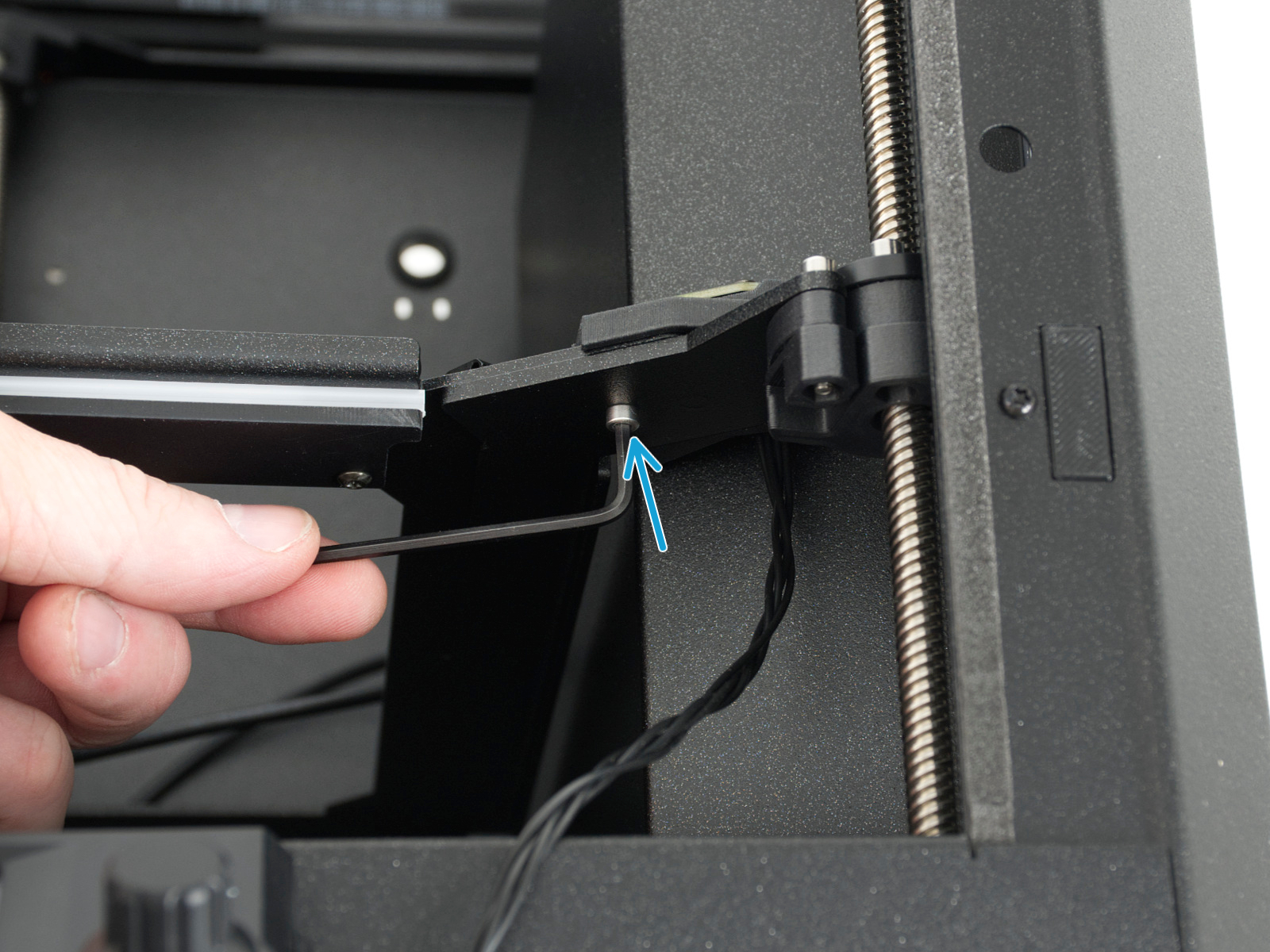
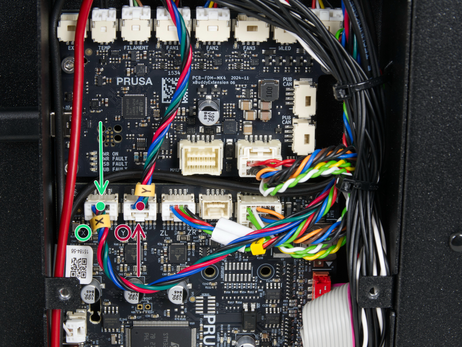
Once the heatbed is secured and the expansion joints are aligned, we can connect the X and Y motor cables and mount the left-side cover.
Follow the instructions below:
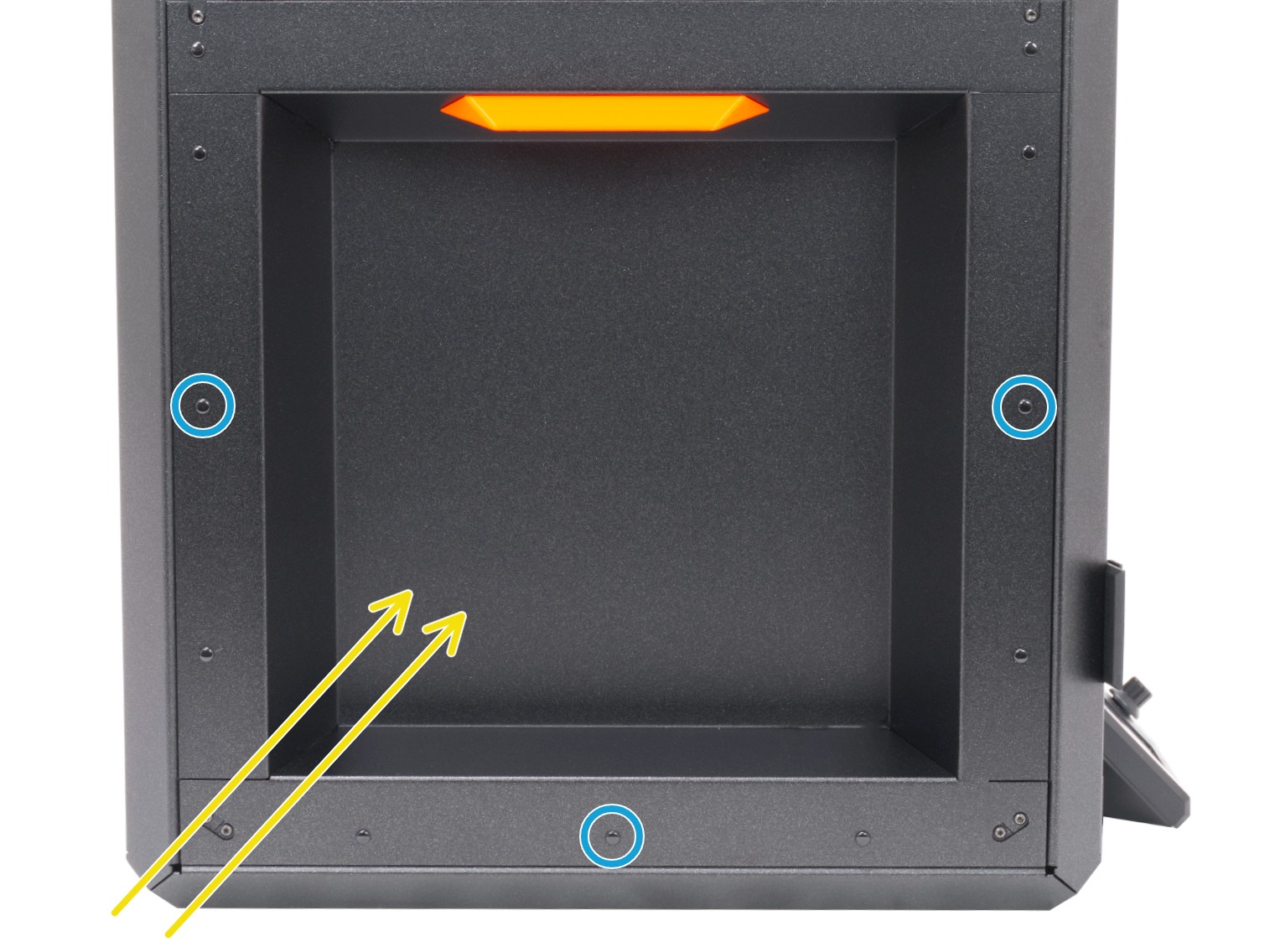
Once the left side cover is secured in place with three nylon rivets, we are finished with the CORE One GEN 2 guide.
Return to the Prusa INDX guide to step ELECTRONICS COVERS: PARTS PREPARATION and follow the rest of the Prusa INDX guide to finish the conversion.
15 comments
In comparison, the assembly instructions for upgrading the CORE One to both GEN2 and INDX at the same time are quite poor. They require a lot of repeatedly switching between different pages, which is particularly inconvenient for users working in an offline environment.
Would it be possible to provide a PDF document with a complete, step-by-step guide for upgrading the CORE One to both GEN2 and INDX simultaneously? Having a comprehensive guide that can be downloaded and read offline would be greatly appreciated and is really needed.
I’ve been upgrading since the original MK3, including every upgrade and MMU generation, and I’ve never been this confused. Part of the Prusa experience is imho the build itself and getting to know every part of the printer while assembling it. That was always fun for me.
This build is not fun. It’s a constant struggle to figure out whether I’m still on track or have missed a crucial step across the multiple parallel guides.
I understand that setting up these guides involves a lot of work, but I’d argue that creating separate guides for separate build paths would reduce complexity for Prusa as well.
I would appreciate it if Prusa returned to its roots when it comes to quality and the build experience.