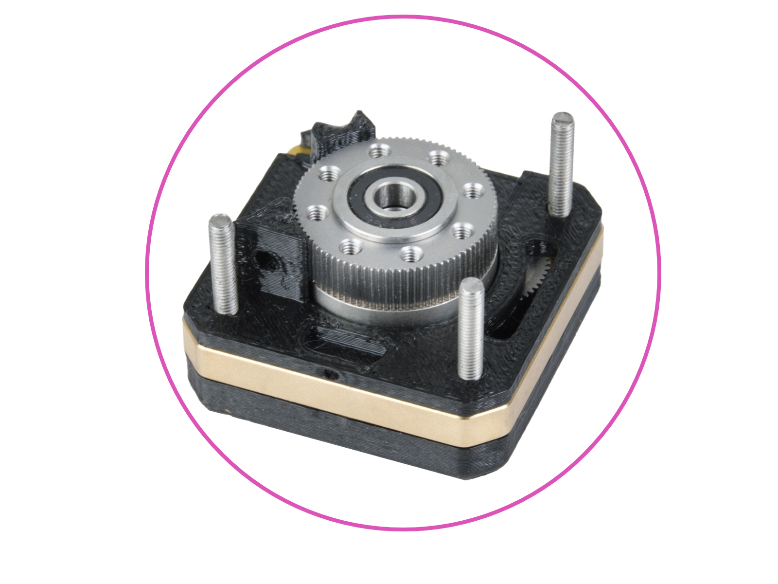
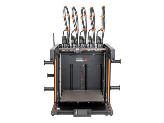
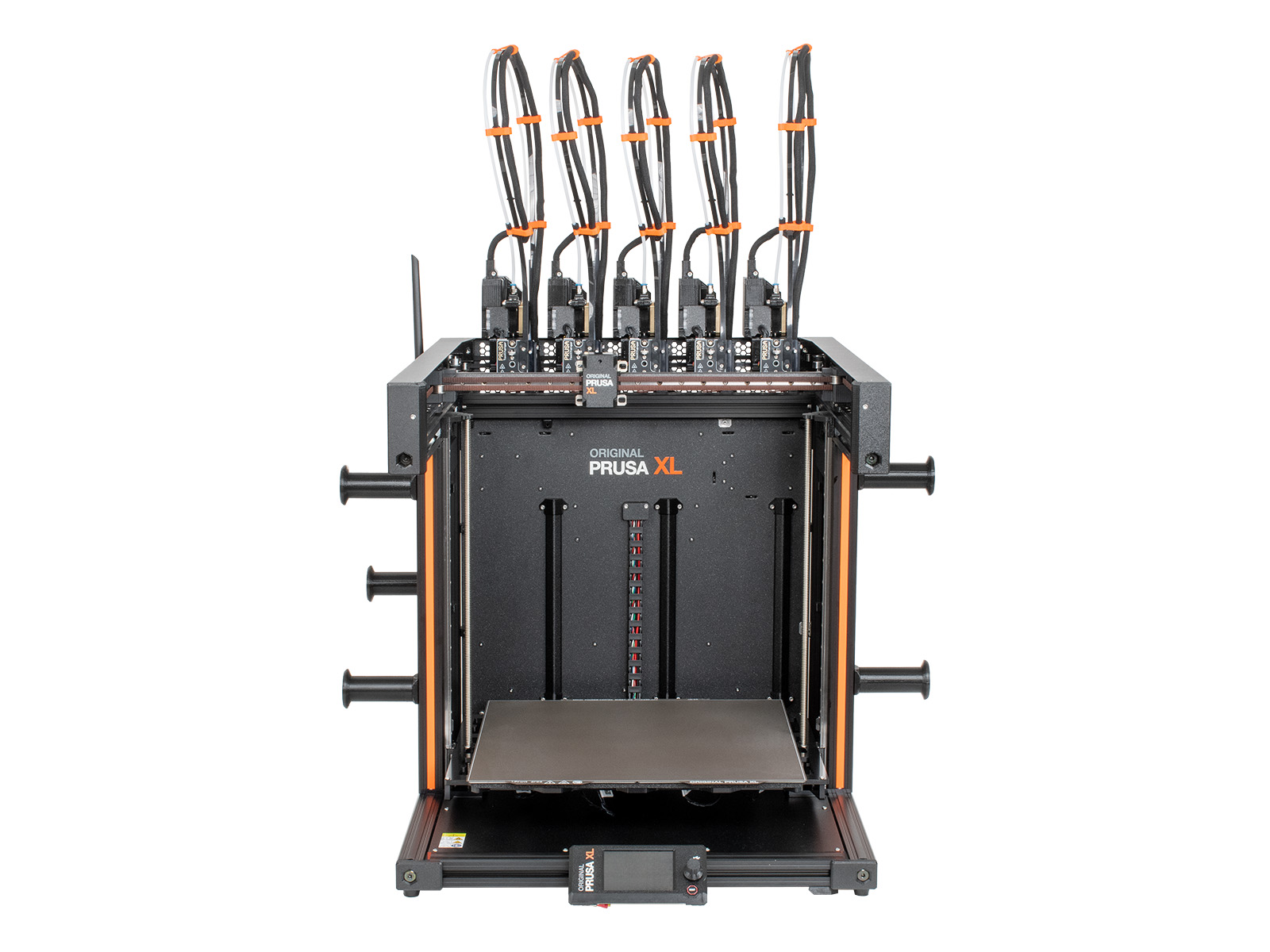
IT
  • English
  • Čeština
  • Deutsch
  • Polski
  • Français
Login

How to replace Nextruder heatsink (XL Multi-tool)

Menu

How to replace Nextruder heatsink (XL Multi-tool)

How to replace Nextruder heatsink (XL Multi-tool)
Rilevante per:
Ultimo aggiornamento 11 hours ago
How to replace Nextruder heatsink (XL Multi-tool)
 Difficoltà
Molto difficile
 Passi
44
 Lingue disponibili
ENCSPLDEFR
Introduction
Introduction
This guide will take you through the replacement of the heatsink on the Original Prusa XL (Multi-tool).
The following instructions are intended for XL multi-tool only, although most steps are common. A single-tool version will be offered at a later time.
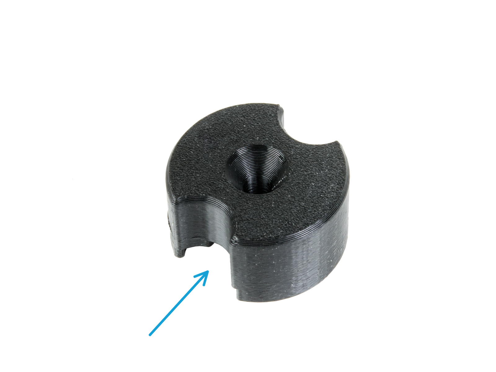
Alcune parti potrebbero essere leggermente diverse. Tuttavia, ciò non influisce sulla procedura.
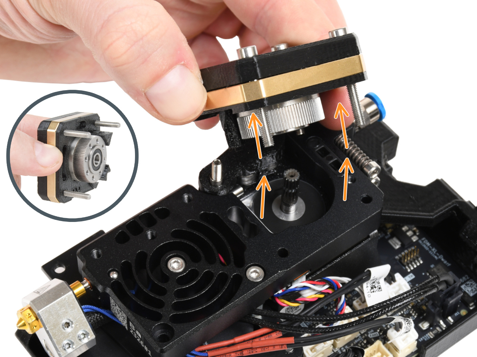
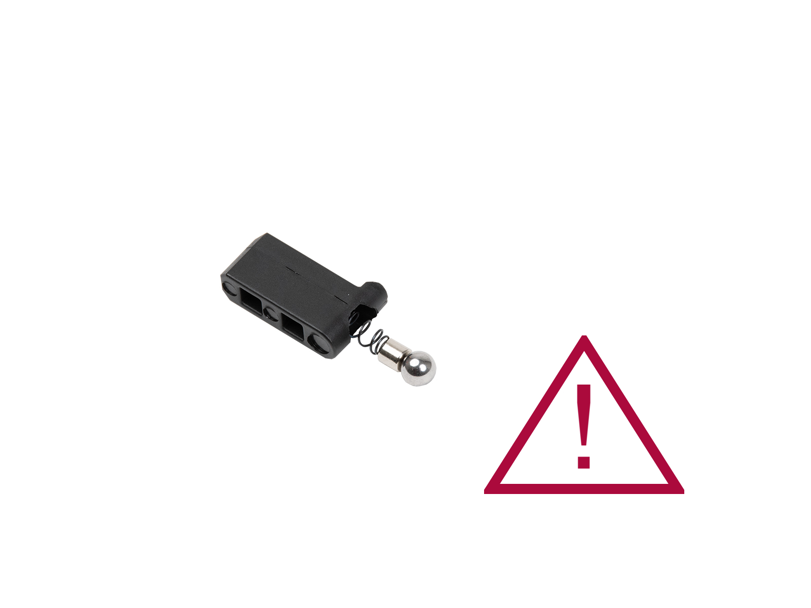
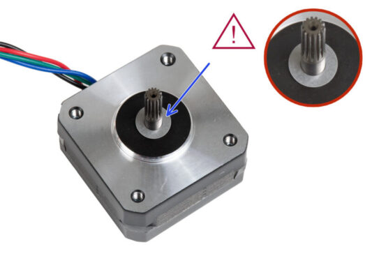
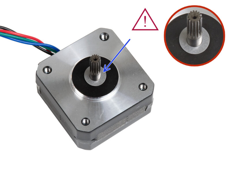
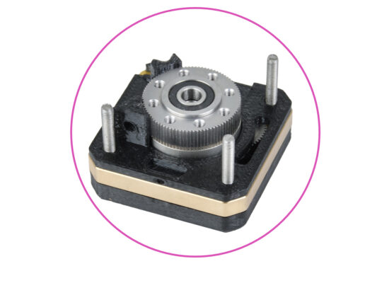
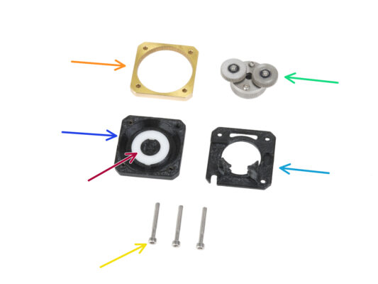
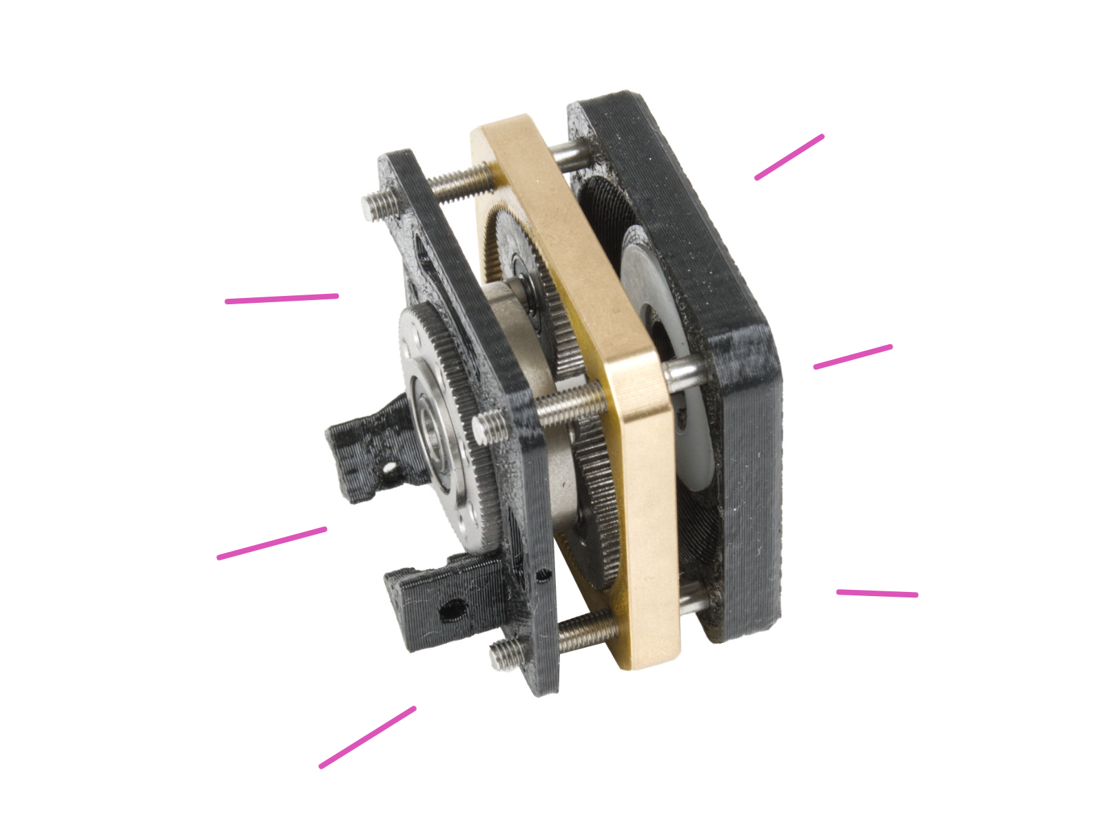
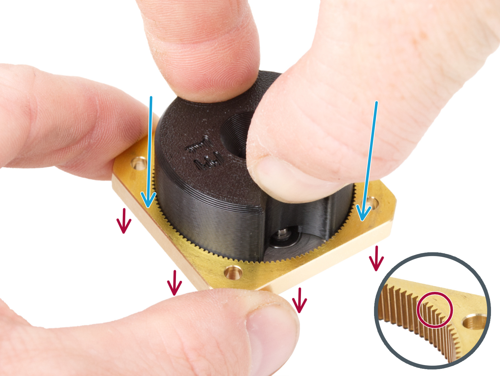
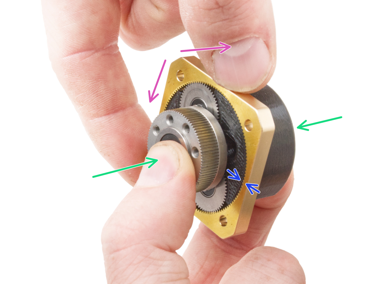
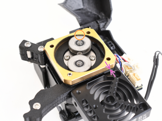
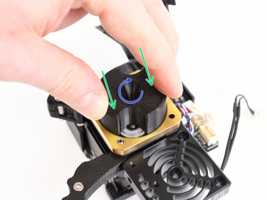
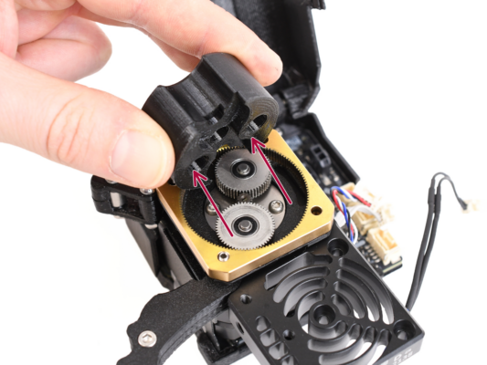
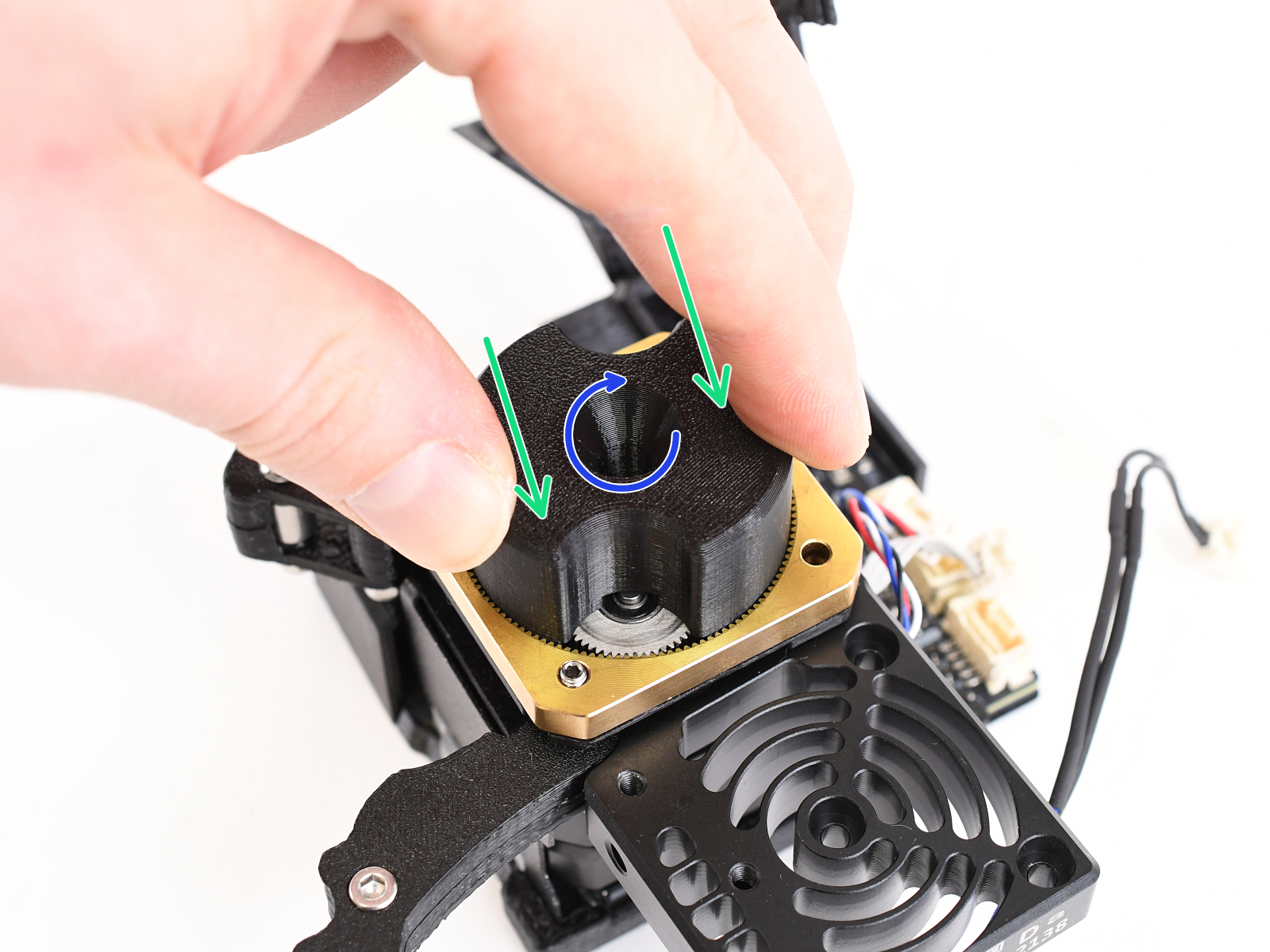
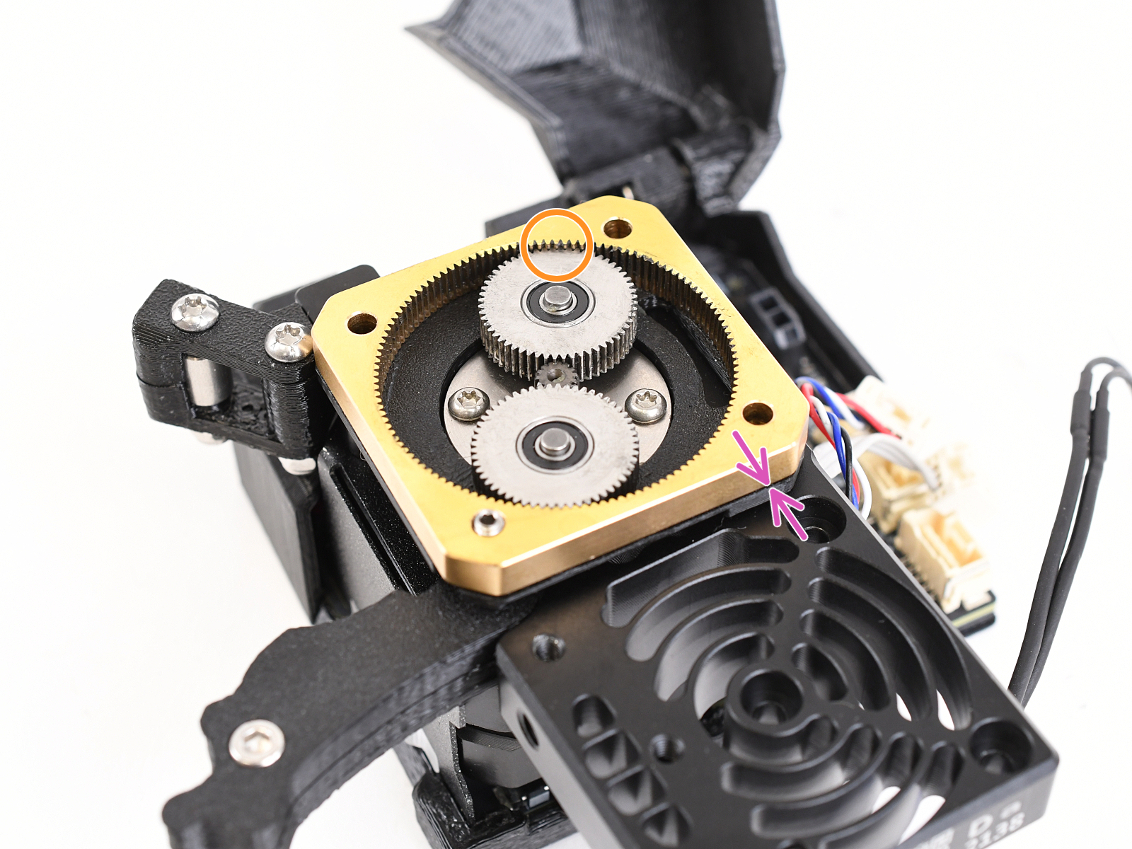
The following instructions require extreme attention. The procedure involves direct intervention in the planetary gearbox.
Attrezzi necessari per questa guida
Per questa guida prepara:
Torx TX10 key
Torx TX6 key
Torx TX8 key
Chiave a brugola da 2.5mm
Universal wrench
Nose pliers
Side cutters recommended for cutting zip ties
Additional parts
Additional parts
Additional parts
Per questa guida prepara:
Prusa lubricant (1x) supplied with your printer
PG-assembly-adapter (1x)
The PG-assembly-adapter is not included in the box and needs to be printed. You can download the STL file from printables.com.
The STL file is located in Parts for maintenance section. Before proceeding, please ensure to review the recommended print settings provided in the caption.
DO NOT continue without the PG-assembly-adapter. It is necessary for the assembly!
Unloading filament
Unloading filament
Unloading filament
Unloading filament
The following step is only necessary if you have a filament loaded in the current toolhead.
Unload the filament from the hotend. On the screen, navigate to Filament -> Unload Filament and select the tool, you want to working on.
Rimuovi il filamento dall'hotend. Non è necessario rimuoverlo completamente dalla stampante. È sufficiente che si trovi a pochi centimetri dall'estrusore.
Raffredda la stampante a temperatura ambiente. Sullo schermo, vai su Preriscalda -> Raffredda.
CAUTION: Wait for the printer to fully cool down to room temperature before proceeding further.
Preparing the printer
Sullo schermo della stampante, vai su Controllo -> Scegli/Parcheggia strumento -> Parcheggia strumento attuale.
Spegni l'interruttore di alimentazione (simbolo "O").
Dal lato posteriore della stampante, scollega il cavo dell'alimentatore.
Protecting the heatbed
Prima di procedere, si raccomanda di proteggere il piano riscaldato.
Assicurati che il piano riscaldato sia raffreddato a temperatura ambiente. Posiziona la scatola di cartone vuota verso la parte anteriore centrale del piano riscaldato.
Scollegare il fascio di cavi del nextruder
On the selected toolhead you want to work on:
Locate the FESTO (QSM-M5) fitting, press the blue collet and unplug the PTFE tube from the second Nextruder. Leave the PTFE hanging freely.
Individua il cavo Nextruder, premi il perno di sicurezza e scollega il cavo dal secondo Nextruder. Lascia il cavo appeso.
Nextruder unlocking
Nextruder unlocking
Nextruder unlocking
On the selected toolhead you want to work on:
Dal lato anteriore del Nextruder, utilizzando un cacciavite T10, allenta (bastano pochi giri) due viti M3x8r e togli il supporto del cavo.
Gently undock the Nextruder and put it aside.
Rimuovere la scheda ToolChanger
Using a T10 screwdriver, remove the M3x30 screw holding the fan-shield.
Turn the nextruder with the print fan facing up.
Remove the M3x8rt screws from the tool-changer using a T10 screwdriver..
Unplug the toolchanger cable. Press the safety latch while disconnecting the connector.
Remove the toolchanger from the Nextruder.
Accesso alla scheda Dwarf
Loosen the M3x16 screw, just a few turns are enough to release the dwarf-cover-door. No need to removing the screw completely.
Open the dwarf-cover-door widely.
Removing the heatsink fan
Remove two M3x20rT screws from the heatsink fan using a T10 screwdriver.
Ogni connettore è dotato di un fermo di sicurezza. È necessario premere il fermo prima di scollegarlo. In caso contrario, il connettore potrebbe danneggiarsi.
Unplug the heatsink fan cable from the Dwarf board.
Remove the heatsink fan and put it aside.
Opening the extruder idler
Push the idler-swivel upward.
Pull the idler-lever downward in order to release tension on the gearbox.
Removing the gearbox & motor assembly
Fully loosen three M3x25 screws from the printed gearbox cover. Keep the screws in the assembly, don't remove them completely.
Carefully slide the gearbox assembly off. It is necessary to remove the entire assembly in one piece. This means PG-cover (top plastic cover), PG-ring (brass ring), PG-assembly (metal gears), and main-plate (bottom plastic plate), all joined by M3x25 screws.
Set the gearbox assembly and the extruder motor aside.
Pay attention to not lose the spacer from the motor shaft.
Removing the hotend
Removing the hotend
Removing the hotend
Removing the hotend
Unplug the hotend thermistor cable from the Dwarf board. Press the safety latch while disconnecting the connector.
Unplug the hotend heater cable from the Dwarf board. Press the safety latch while disconnecting the connector.
With a Torx TX 8 key loosen the grub screw in the extruder. Do not remove the screw completely. A few turns are enough to release the hotend assembly in the heatsink.
Carefully pull the hotend assembly out of the heatsink.
At the same time pull the disconnected hotend cables from below the heatsink.
Removing the heatsink assembly
Unplug all remaining cables from the Dwarf board. Press the safety latch while disconnecting each connector.
Remove the heatsink assembly and set it aside.
Rimuovere la ventola di stampa
Remove the two M3x10 screws from the heatsink with a 2.5 mm Allen key.
Separate the heatsink and the print fan.
Set the print fan aside. We will need it later again.
Removing the idler-swivel
Remove the two M3x30 screws to remove the idler-swivel from the heatsink.
Remove the idler-swivel from the heatsink.
Remove the festo with a universal wrench.
Be careful to not lose the springs.
Removing the NTC thermistor & Hall sensor
Unscrew the M2.5x6rT screw to remove the Hall filament sensor. Carefully remove the Hall filament sensor.
Carefully remove the Hall filament sensor.
Release the set screw from the bottom of the heatsink to remove the NTC thermistor.
Pull the NTC thermistor out from the heatsink.
Rimuovere il sensore di filamento
BE EXTRA CAREFUL when removing the filament sensor. The filament sensor contains a tiny parts (spring, magnet, steel ball) that tend to fall out when the sensor is removed.
Very carefully pull the filament sensor out from the heatsink using the needle-nose pliers.
CAUTION: Avoid gripping the part firmly, as this may cause irreparable damage.
Don't lose the small parts! You will need them again later. Keep them aside in a safe place.
Remove the grub screw from the heatsink.
Tip: store small parts in a box or bowl.
Installing the Hall sensor
Posiziona il sensore Hall del filamento nella cavità di forma simile nel dissipatore di calore.
Fissalo con una vite M2.5x6rT. Stringila con molta cautela, potresti incrinare la scheda elettronica.
Insert the grub screw into the slot closer to the bottom of the heatsink. See the picture.
Installazione del sensore di filamento
Insert the Prusa ball holder assembly into the heatsink. Make sure the steel ball part is closer to the side of the heatsink.
Note the correct orientation of the Prusa ball holder assembly. There is a protrusion on the part. The protrusion must be facing down.
Spingi il gruppo nel dissipatore.
Mounting the idler-swivel
Tighten the idler-swivel with two M3x30 screws.
Note the correct orientation of the part. The screw heads on the idler-swivel must be facing up (like in the picture).
The tip of each screw should be flush with the plastic part on the other side.
Inserting the NTC thermistor
On the extruder motor side, insert the NTC thermistor into the hole in the heatsink.
Secure it with the M3x4T grub screw. Screw it all the way in. Tighten gently, but firmly using two fingers and the short side of the T6 Torx key. Applying more force may cause permanent damage to the thread.
Align the heatsink with the motor assembly.
Double-check that the spacer is still in place on the motor shaft!
Preparing the gearbox parts
Dismantle the gearbox assembly into its component parts:
PG-ring (1x)
PG-assembly (1x)
PG-front-case (1x)
Make sure there is a plastic spacer inside the case. It can be black or white. Do not remove the plastic spacer from the case.
Main-plate (1x)
M3x25 screw (3x)
Using a paper towel clean all the parts from grease.
Assembling the gearbox
In the following steps, we will reassemble the entire gearbox assembly to ensure proper installation.
Le seguenti istruzioni devono essere eseguite correttamente e con attenzione. Per capire meglio e assemblare correttamente il tutto, guarda il video allegato alla guida: prusa.io/PG-assembly
The video is for MK4, but the procedure is identical.
Dopo aver visto il video, segui i passi di questa guida.
Monta l'adattatore PG-assembly-adapter sul gruppo PG. Nota le tasche per gli ingranaggi nell'adattatore.
Assembling the PG-ring
Non assemblare il riduttore senza l'adattatore PG-assembly-adapter. Questo strumento serve a garantire che gli ingranaggi vengano montati correttamente.
Fai scorrere l'anello PG-ring sull'adattatore.
Nota che c'è uno smusso su un lato dei denti dell'anello PG-ring. Questo lato deve essere rivolto verso il basso (verso il gruppo PG).
Afferra l'intero gruppo con una mano in modo da poterlo ruotare con l'anello PG-ring.
Con l'altra mano, fai scorrere l'anello PG-ring sul gruppo PG con un movimento oscillante (muovi l'anello PG a destra e a sinistra ripetutamente) - un quarto di giro è sufficiente.
Fermati quando le superfici degli ingranaggi sono approssimativamente a filo con la superficie dell'anello PG.
Mounting the gearbox
Procedi con molta attenzione in questa fase.
Attach the main-plate on the heatsink. Note the orientation of the part. Use the cutout for the socket screw as a guide (lower left corner).
Mantieni la posizione del gruppo PG-assembly e fissalo all'albero del motore dell'estrusore.
Make sure the PG-ring perfectly fits on the socket set screw.
Very gently and freely rotate with the whole PG assembly (PG-assembly-adapter, PG-assembly and PG-ring) until it drops down so that there is minimal gap between the assembly and the main-plate. Do not push on the assembly.
Remove the PG-assembly-adapter.
Checking the PG assembly
Attach the PG-assembly-adapter back on the PG-assembly again to verify that all parts are properly seated.
Rotate with the PG-assembly-adapter. The PG assembly must be easy to rotate without having to exert much force.
Remove the PG-adapter. You will no longer need it during assembly. We recommend keeping it for maintenance.
Assicurati che il gruppo PG-assembly non sporga al di sopra dell'anello PG-ring. Deve essere posizionato più in basso o allo stesso livello della superficie dell'anello PG-ring.
Non ci deve essere spazio tra l'anello PG-ring e la piastra principale. Se si nota uno spazio, rimuovi il gruppo ingranaggi planetari e riposizionalo.
Lubricating the gears
Open the Prusa Lubricant. Using the opposite side of the cap, puncture the hole in the opening of the tube.
Applica una piccola quantità di lubrificante Prusa intorno all'anello PG-ring e ai denti del gruppo PG-assembly.
Tip: apply a small amount of lubricant to the tip of the zip tie and then spread the lubricant over the gears.
Con un tovagliolo di carta, elimina il lubrificante in eccesso sulle superfici anteriori.
Covering the gearbox
Place the PG-case on the gearbox.
Insert three M3x25 screws into the PG-case, but do not tighten them completely. They will be tightened later.
Close the idler-lever and lock it in position with the idler-swivel.
Connettere i cavi del Nextruder
Plug the load cell sensor cable into the Dwarf board.
Plug the filament sensor cable into the Dwarf board.
Plug the heatsink thermistor cable into the Dwarf board.
Montaggio della scheda Tool Changer e del gruppo ventola di stampa
Prepare the Tool changer board & print fan assembly.
Align the three metal spacers with the holes in the heatsink, make sure the board and fan cables are guided below the top spacer before you attach the heatsink, so that they are not pinched.
Use three M3x10 screws to attach the heatsink & gearbox assembly to the spacers on the print fan cover. Start with the center screw, and be careful to not pinch any cables
Montare la ventola dell'hotend
Attach the hotend fan to the heatsink with its cable positioned as can be seen in the picture.
Mind the orientation of the fan.
Secure the heatsink fan with two M3x18rT screws.
Plug the print fan cable into the Dwarf board.
Plug the toolchanger cable into the Dwarf board.
Collega il cavo della ventola dell'hotend alla scheda Dwarf.
Reattaching the toolchanger board and the hotend
Attach the toolchanger board with the heat shield to the Nextruder.
Secure the fan shield with a M3x30 screw.
Insert the hotend into the heatsink.
Lead the hotend cables between the heatsink spacers as shown in the picture and make sure that they are not pinched.
Plug in the hotend thermistor cable.
Plug in the hotend heater cable.
Fissare il tool-changer e l'hotend
Fissa il tool-changer con due viti M3x8rt.
Connetti il cavo del toolchanger.
While pushing the hotend into the heatsink, tighten the grub screw with a Torx TX 8 key.
Mounting the festo
Mounting the festo
Mounting the festo
Mount the festo on the top of the heatsink.
Gently tighten the festo with a uni-wrench.
Connecting the nextruder
Inserisci il tubo in PTFE nel raccordo Festo quanto più possibile. Tira leggermente il tubo in PTFE per assicurarti che sia ben fissato.
Collega il cavo Dwarf dell'estrusore alla scheda Dwarf.
Slide the black nylon plate onto the screws in the Cheese board, and tighten them with a Torx T10 key.
Assicurarsi che la piastra di nylon non sia attorcigliata.
Docking the tool
Docking the tool
Docking the tool
Docking the tool
Ruota con attenzione la stampante in modo che il lato anteriore sia rivolto verso di te.
Prendi il Nextruder e posizionalo con attenzione accanto al dock.
Inserisci i due inserti metallici nei fori bianchi del dock. I magneti ti aiuteranno ad agganciare il Nextruder.
Controlla che la guarnizione dell'ugello tocchi leggermente l'ugello.
Wizard
Wizard
Wizard
From the rear side of the printer, plug in the PSU cable.
Turn the power switch ON (symbol "I").
Run the tests from the Control - Calibration & Tests menu.
The wizard will test all important components of the printer. The whole process takes a few minutes. Some parts of the wizard require direct user interaction. Follow the instruction on the screen.
NOTE: While testing the axes, make sure that there is nothing in the printer that is obstructing the movement of the axes.
WARNING: Do not touch the printer during the wizard unless prompted! Some parts of the printer may be HOT and moving at high speed.
Calibrating the Nextruder gears
Collega la stampante e accendila.
Now we need to simulate the movement of the gearbox. On the LCD screen, navigate to Filament - Unload filament.
As soon as the extruder's movement finishes, tighten the three M3x25 screws on the PG-case in the correct order (shown on the picture).
Then loosen the screws slightly and repeat the process, tightening the screws in the correct order. This ensures that the gearbox is seated correctly.
Well done!
Well done!
Congratulations, you have just successfully replaced the heatsink on your Original Prusa XL!
Questa guida è stata utile?

Commenti

Hai ancora delle domande?

Hai ancora delle domande?

Se hai una domanda su qualcosa che non è trattato qui, dai un'occhiata alle nostre risorse aggiuntive.
E se questo non dovesse funzionare, è possibile inviare una richiesta a [email protected] o tramite il pulsante qui sotto.

Contattaci