
Contents
Printer maintenance
- How to replace the xBuddy board (MK4/MK3.9/MK3.5)
- How to replace a Heatbed Thermistor (MK4/S, MK3.9/S, MK3.5/S)
- How to replace xLCD (MK4/MK3.9/MK3.5)
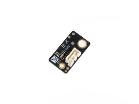
- How to use accelerometer (MK3.5/S)
- Begin assembly
- Introduction
- Tools necessary for this chapter
- Parts preparation
- Accelerometer assembly
- Preparing the printer
- Opening the xBuddy box
- Connecting the accelerometer
- Calibration part 1
- Calibration part 2
- Calibration part 3
- Calibration part 4
- Disconnecting the accelerometer
- Covering the xBuddy box
- Finish
Comments
Log in to post a comment
No comments