English
Login
3D printers
Materials
Parts & Accessories
For Business
Software
3D Models
Community
Help
Courses
Blog
Company
Support
Original Prusa i3 MK3S
Original Prusa i3 MK3S kit assembly (v3.15)
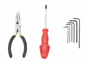
3. X-axis assembly | Tools necessary for this chapter
1. Tools necessary for this chapter
Step 1 of 12 (Chapter 3 of 11)
Contents
Comments
⬢
2.5mm Allen key for M3 screws
⬢
2mm Allen key for nut alignment
Loading...
Next
Contents
Original Prusa i3 MK3S kit assembly
1. Introduction
2. Y-axis assembly
3. X-axis assembly
Tools necessary for this chapter
X-axis: x-end idler and motor holder
X-axis: inserting linear bearings
X-end-motor: tensioner assembly
X-end-idler: bearing assembly
X-axis: smooth rods preassembly
X-axis: assembly
Assembling the X-axis motor pulley (part 1)
Assembling the X-axis motor pulley (part 2)
X-axis: assembling the motor
Haribo time!
X-axis is finished!
4. Z-axis assembly
5. E-axis assembly
6. LCD assembly
7. Heatbed & PSU assembly (Black PSU)
7. Heatbed & PSU assembly (Silver PSU)
8. Electronics assembly
9. Preflight check
Manual changelog
Comments
Log in
to post a comment
Stephen Cooper
•
I don’t see anywhere in this step that zip ties are used. Why are the needle nose pliers mentioned as being needed?
Reply
Martin L. - Official Prusa CS
•
Stephen, you can need them during the manupulation with the bearings, as well as for insterting nuts into their traps.
Reply