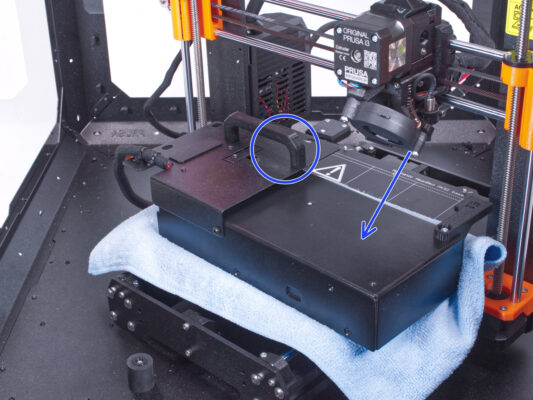
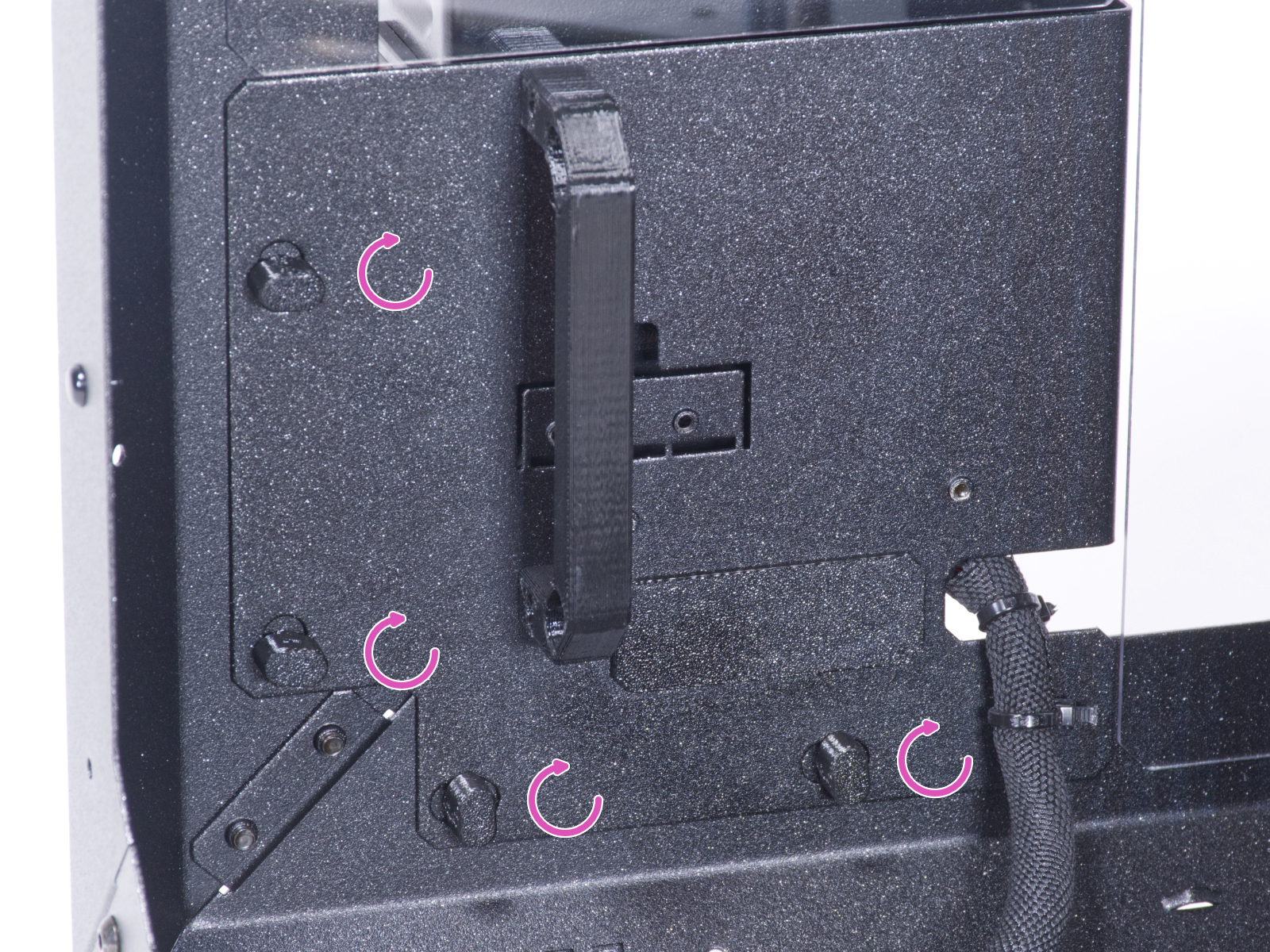
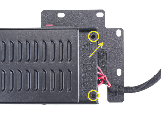
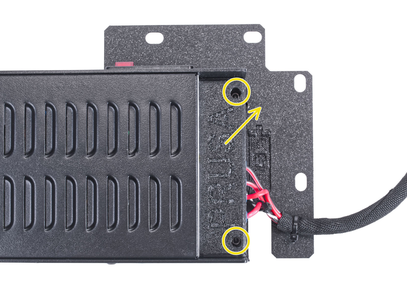
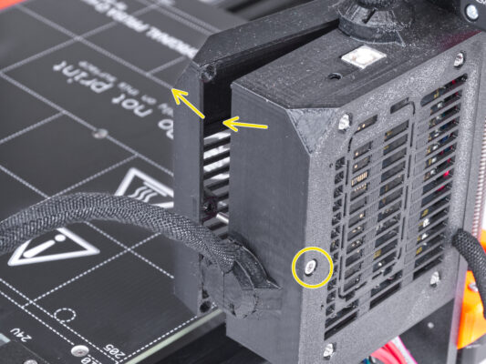
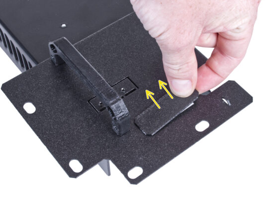
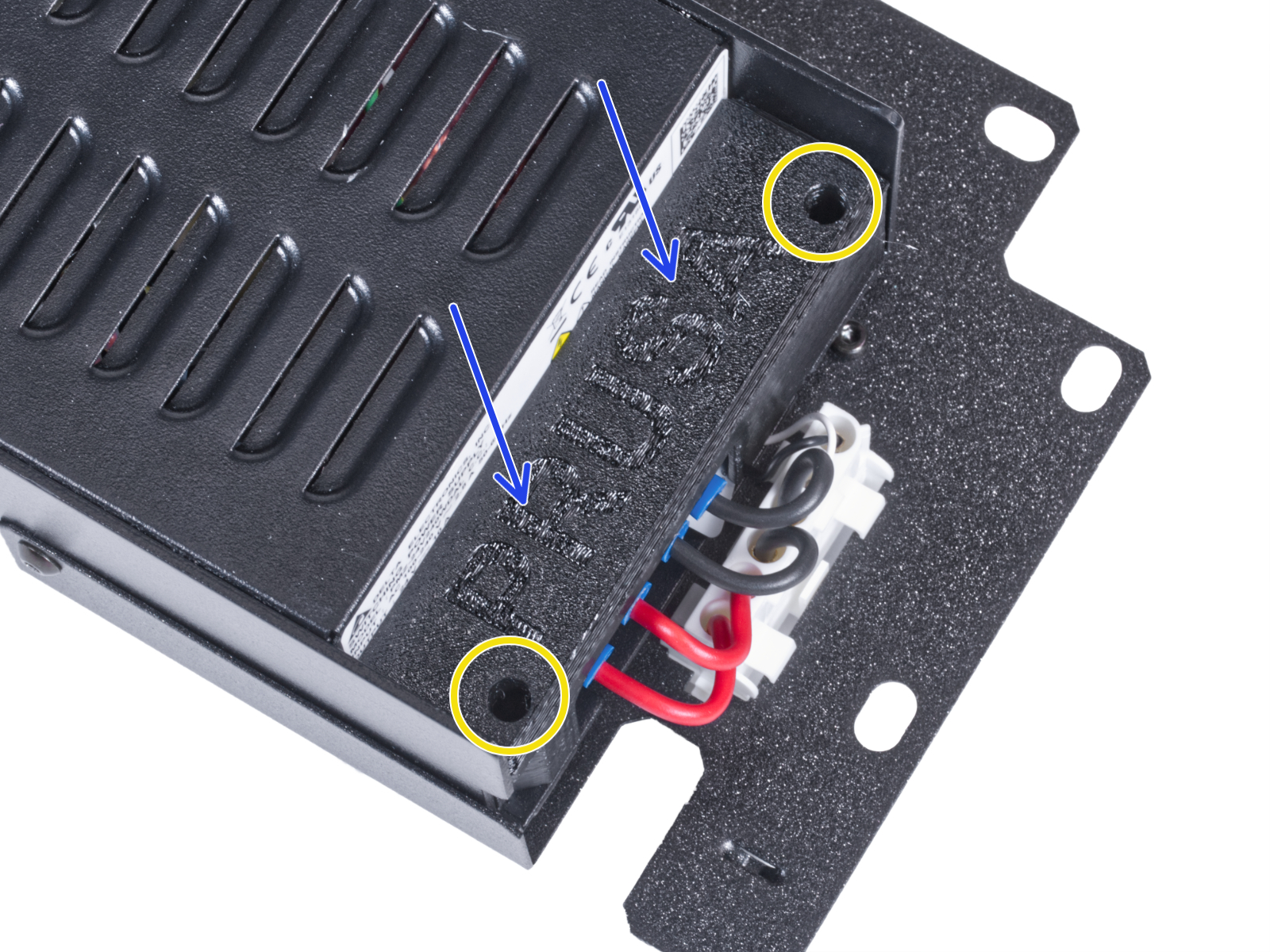
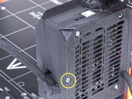
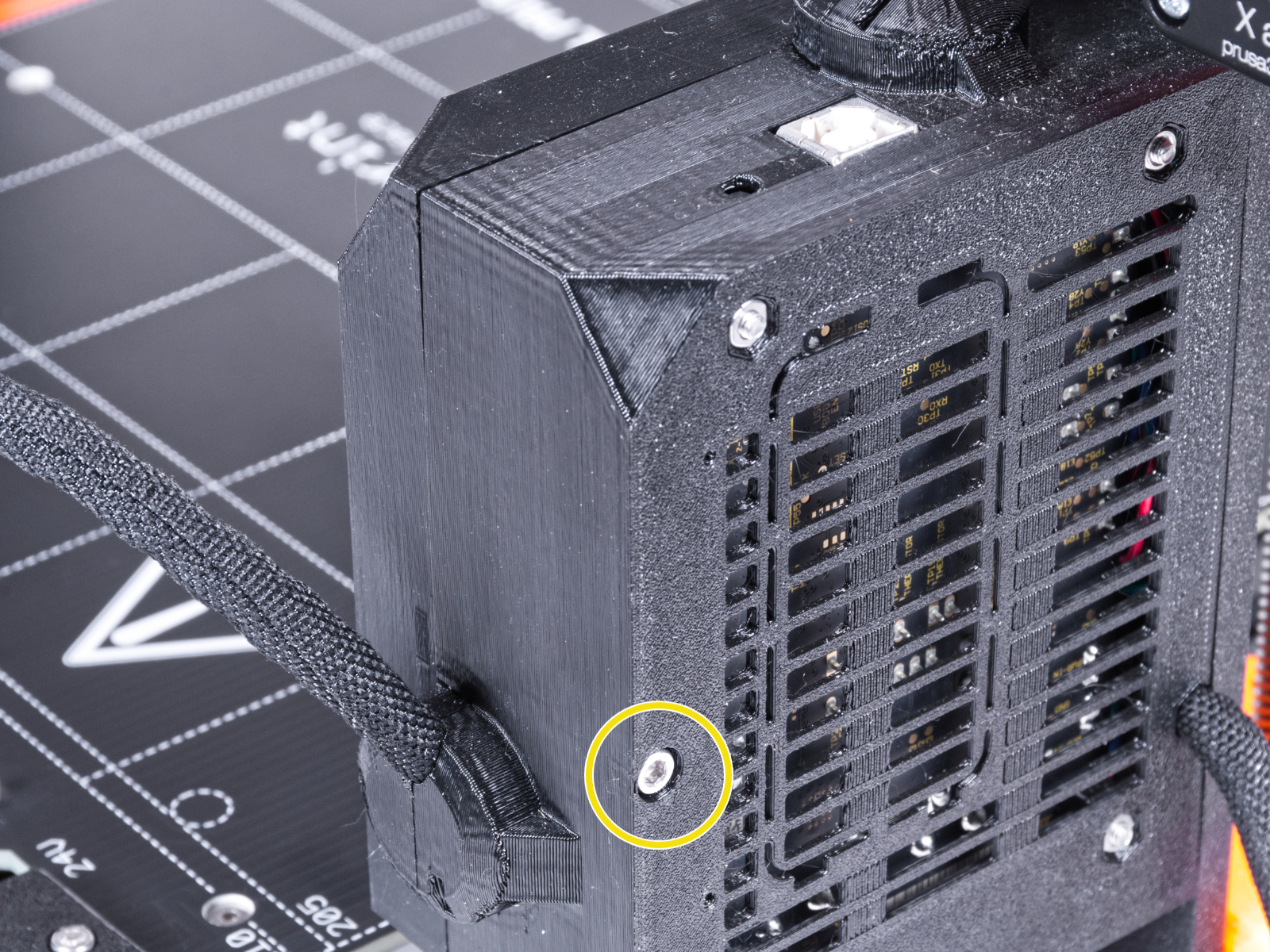
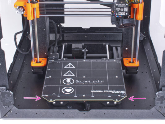
JA
  • English
  • Čeština
  • Español
  • Italiano
  • Deutsch
  • Polski
  • Français
Login

9. Quick release PSU cable - MK3S+ Black PSU (add-on)

9. Quick release PSU cable - MK3S+ Black PSU (add-on)

9. Quick release PSU cable - MK3S+ Black PSU (add-on)
Relevant for:
Last updated 25 days ago
9. Quick release PSU cable - MK3S+ Black PSU (add-on)
 Difficulty
Easy
 Steps
26
 Available languages
ENCSPLDEESITFR
Introduction
Introduction
This guide will take you through the installation of the Quick release PSU cable on the Original Prusa Enclosure.
This addon is not compatible with the Original Prusa MK4.
This add-on is not compatible with the silver PSU.
Buy a compatible black PSU from our E-shop.
Tools necessary for this chapter
Tools are not included in the add-on package.
For this chapter, please prepare:
2.5mm Allen key
Needle-nose or cutting pliers
Phillips screwdriver PH2
Removing the LCD
Removing the LCD
Removing the LCD
Removing the LCD
Carefully cut the zip tie securing the LCD cable bundle.
Release two screws mounting the LCD assembly.
Disconnect both LCD cables from the LCD.
Push the LCD cable bundle through the hole in the bottom panel into the enclosure.
Removing the printer
Press down the blue collet on the Fitting QSM-M5.
Pull out the PTFE tube from the fitting.
Removing the printer
Open the door of the enclosure.
Place the printer at an angle (as shown in the picture) in the enclosure behind the anti-slip dampers.
"Unlock" all PSU-locks and grasp the PSU assembly by its handle and remove it from the back panel.
Place the PSU on the heatbed protected with the cloth. Turn it with the PSU-handle facing upwards.
Removing the printer
Carefully remove the printer from the enclosure.
Avoid scratching the printer and enclosure.
Place the enclosure aside. We will need it later on.
Disconnecting the PSU
On the PSU holder, cut off the zip tie securing the PSU cable.
On the other side of the PSU assembly, loosen two screws mounting the PSU-cover and remove the cover from the PSU.
Using a Phillips screwdriver, loosen all the screws on the PSU cables. No need to remove the screws.
Remove all PSU cables from the terminals.
Disconnect the power panic cable from the PSU.
Place the disconnected PSU aside for now. We'll come back to that later.
Disconnecting the PSU cables
Cut off the zip tie merging both cable bundles.
From the back of the Einsy case, loosen the screw to open the door of the electronic box.
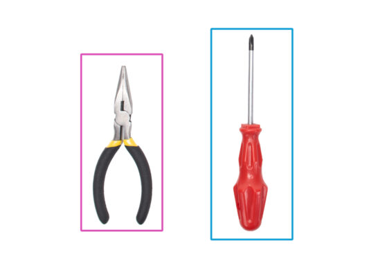
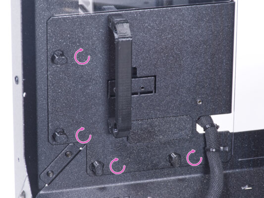
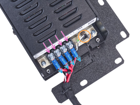
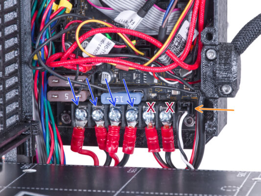
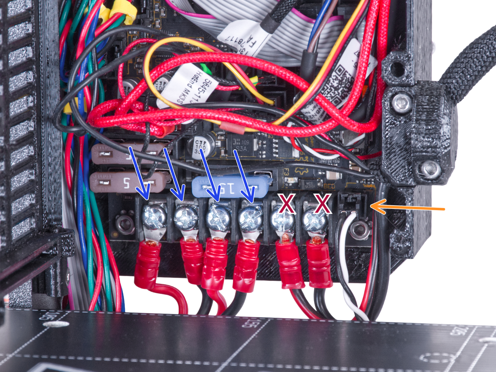
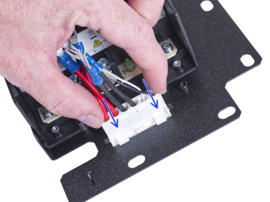
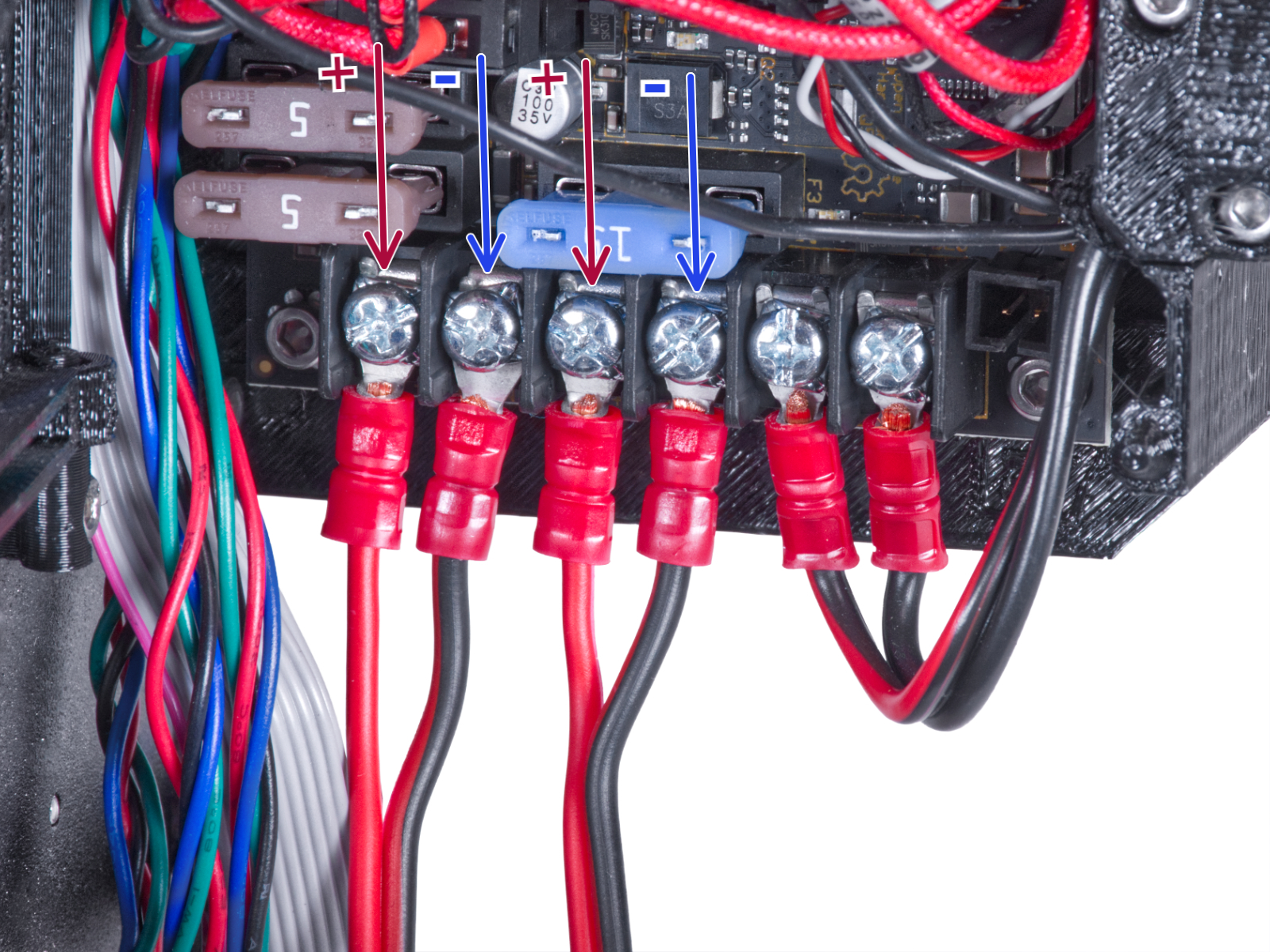
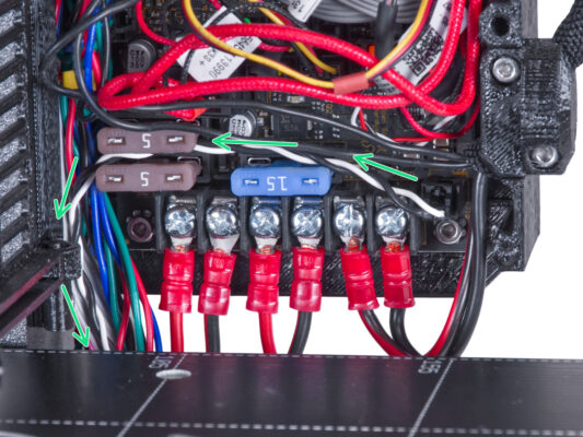
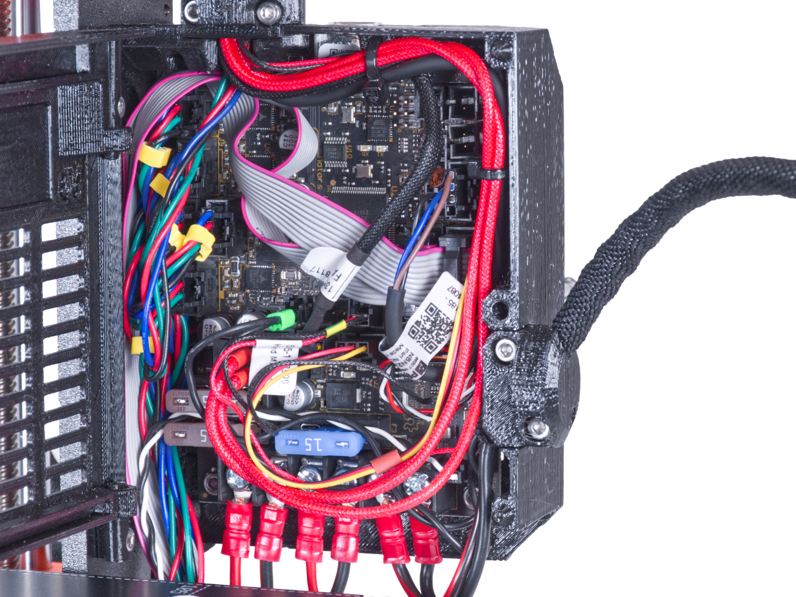
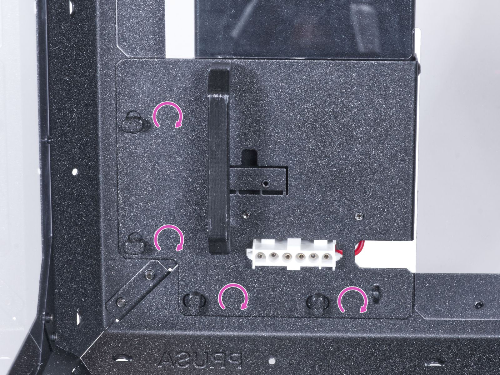
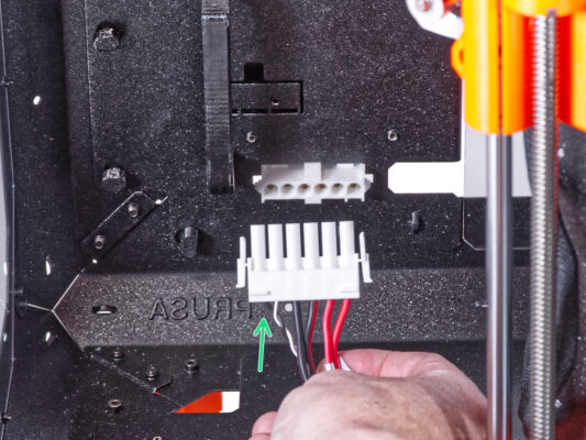
Using the Phillips screwdriver, loosen the screws securing the PSU cables (the first four from the left). And remove all the cables from the terminals.
Do not disconnect the heatbed power cables (the last two cables)!
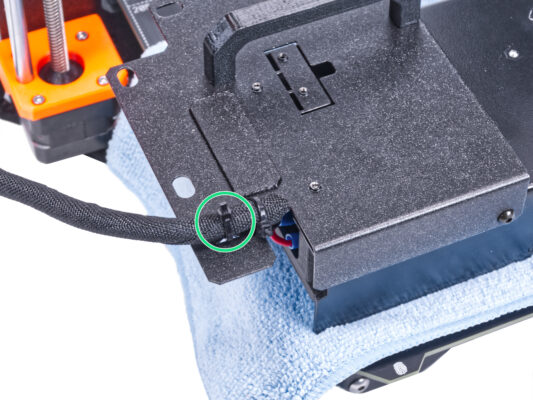
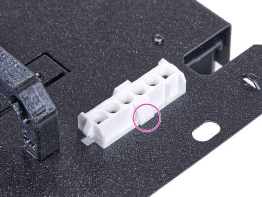
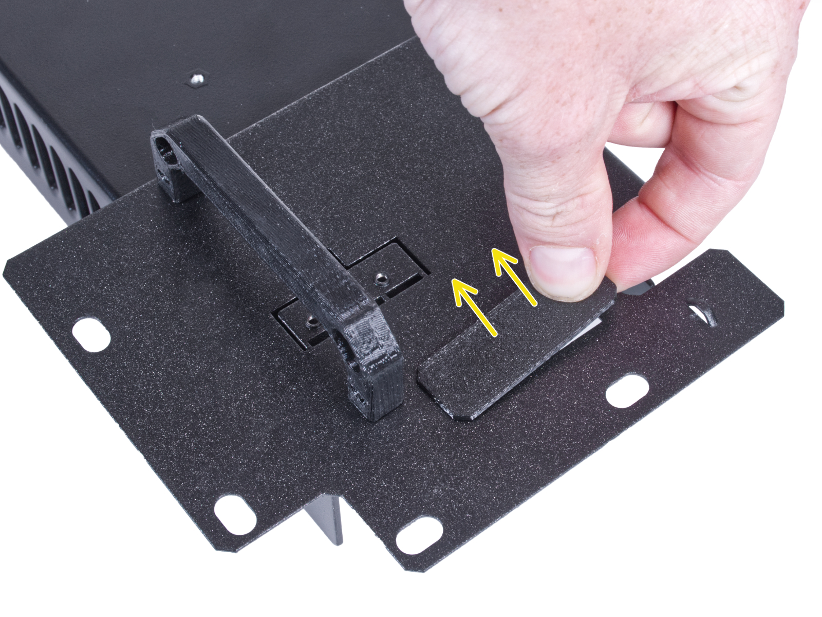
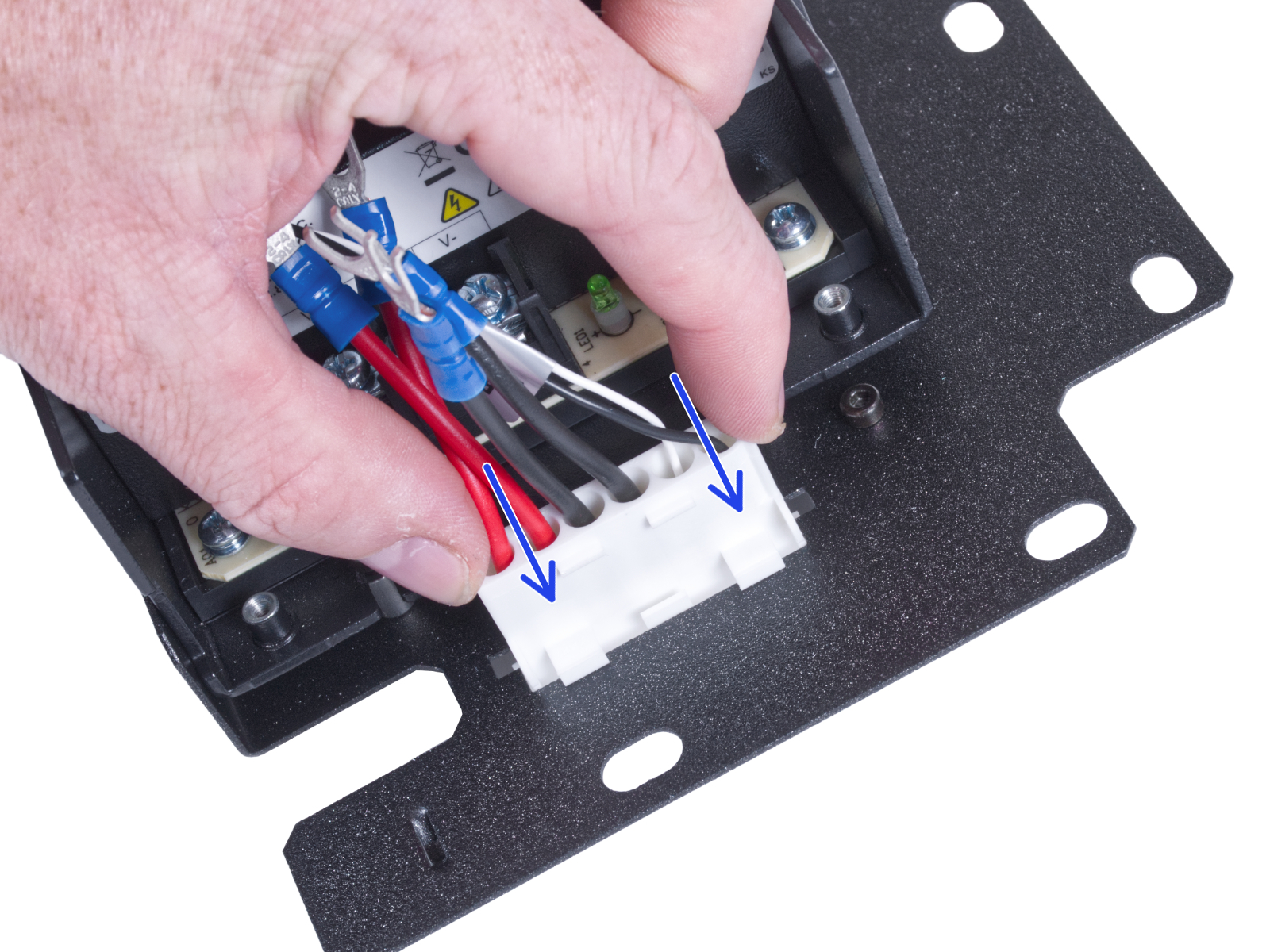
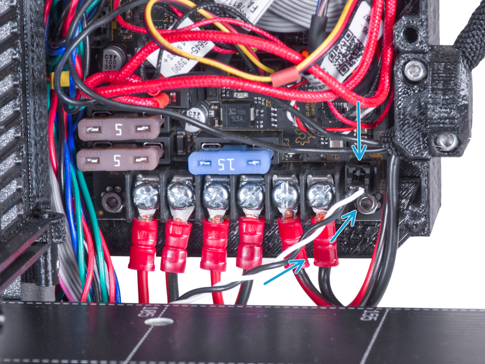
Disconnect the Power panic cable from the electronics board.
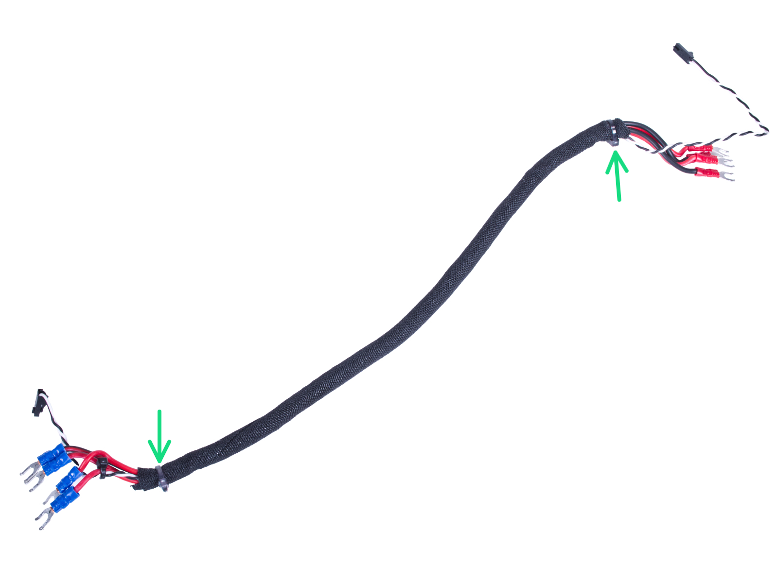
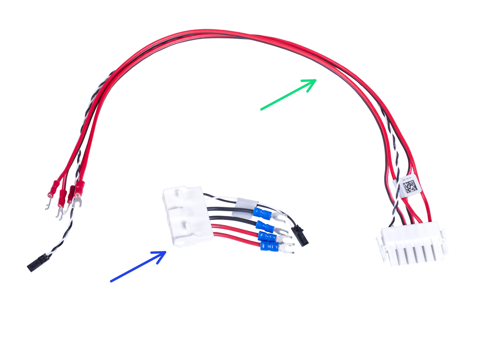
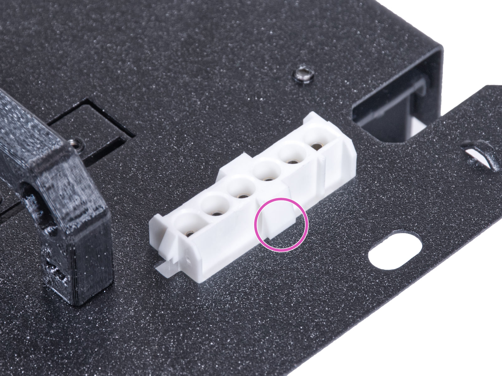
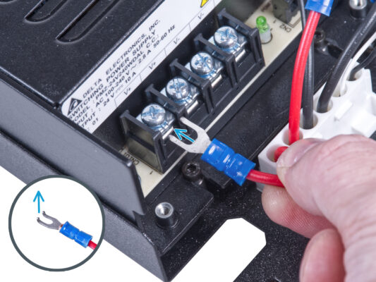
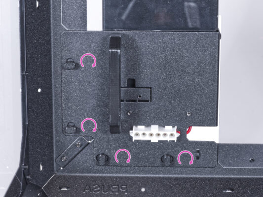
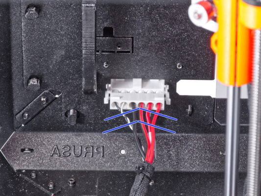
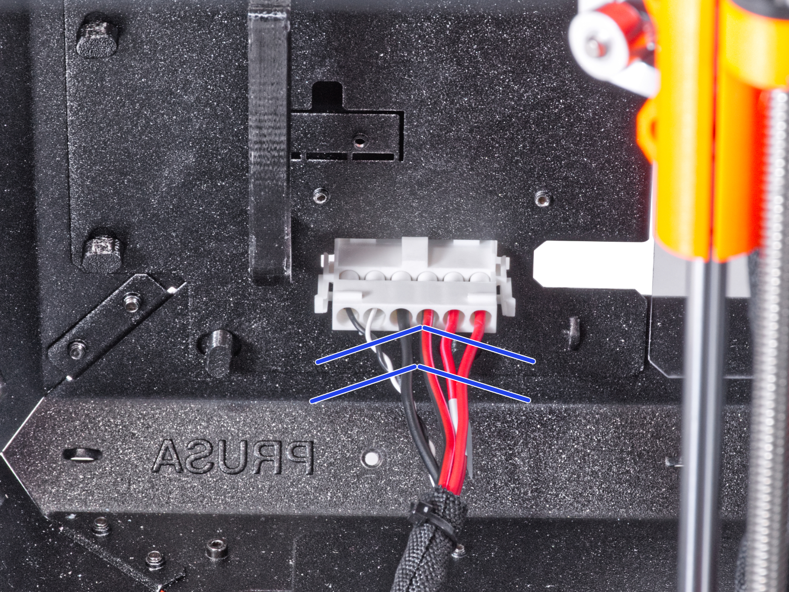
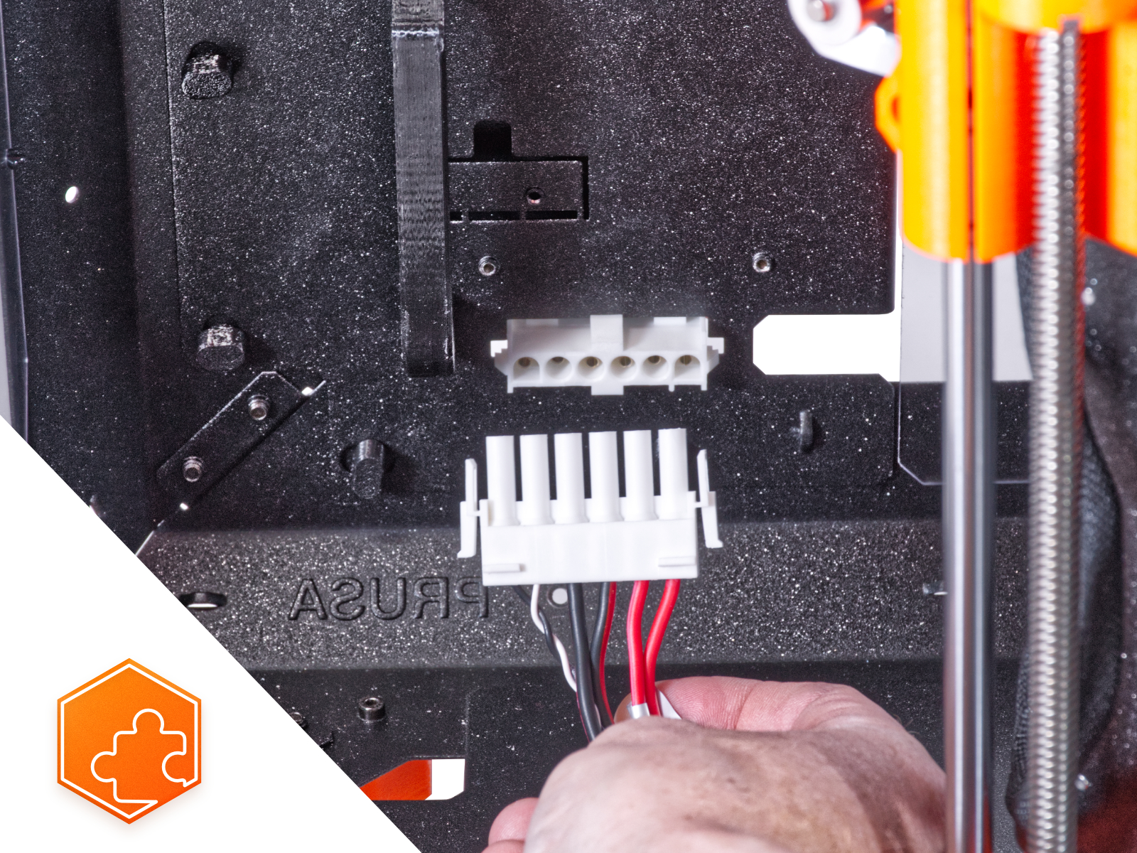
Keep the electronics box open.
Disconnecting the PSU cables
Cut the zip ties on both ends of the textile sleeve and remove the sleeve from the cable bundle.
You will no longer need this cable bundle. However, we recommend not discarding it. Keep it as a spare.
Installing the quick release cable
Remove the plug from the PSU holder.
Insert the Quick Release cable - Black PSU Side into the hole in the PSU holder.
From the opposite side of the PSU holder check that the latches on the connector are engaged with the metal sheet.
Connecting the PSU cables
Take the first positive (red) wire from the Quick Release cable - Black PSU Side connector and connect it to the first terminal from the left on the PSU. Bent part of the connector is facing up. Push it below the square washer, all the way in.
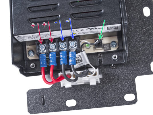
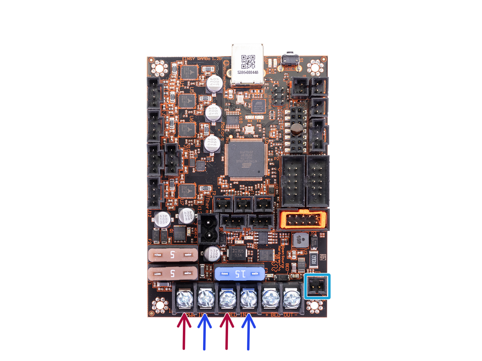
Use this method for all PSU cables and connect them in the following order:
POSITIVE (red) wire
POSITIVE (red) wire
NEGATIVE (black) wire
Check the connection again! The red wire is in the first slot and black in the third. Make sure that cables are properly tightened. Otherwise, there is a risk of damage to the printer!
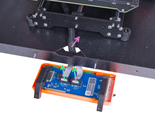
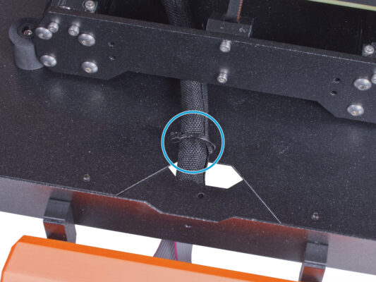
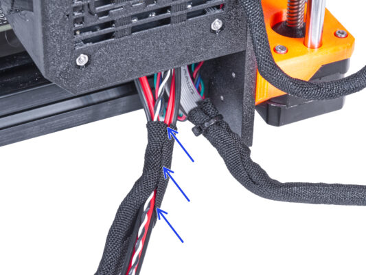
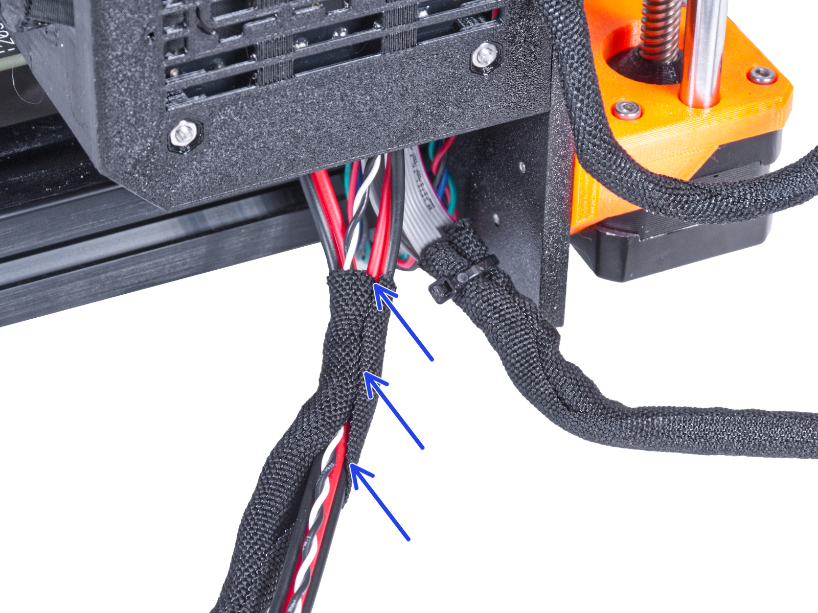
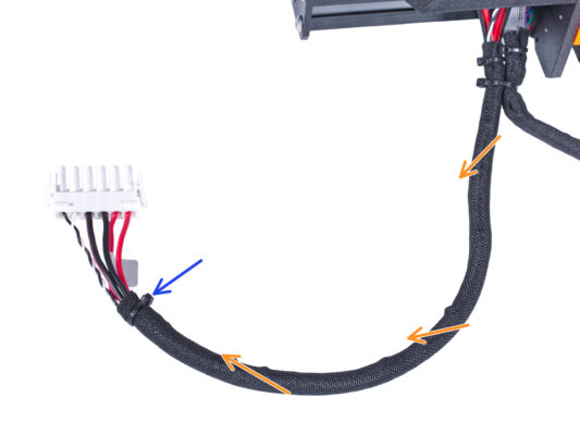
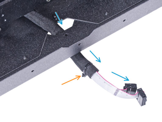
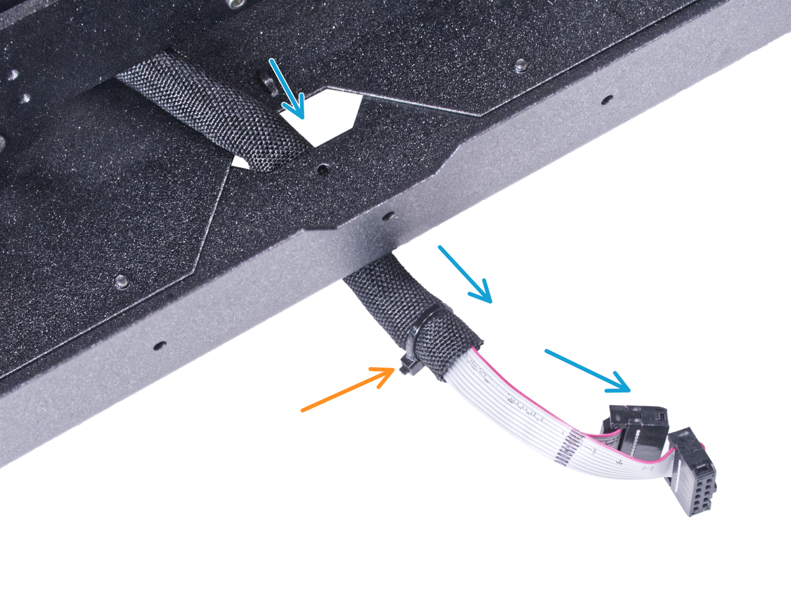
Connect the power panic cable to the PSU.
Covering the PSU
Covering the PSU
Slide the cover on the cables from the top. Make sure the "PRUSA" logo is facing up.
Secure the cover using two M3x10 screws. Note that the holes are quite deep.
電源のケーブルを接続する
電源のケーブルを接続する
電源のケーブルを接続する
電源のケーブルを接続する
Connect the quick release power cables to the Einsy board in the following order (from the left):
POSITIVE (red) wire
NEGATIVE (black, black/red) wire
POSITIVE (red) wire
NEGATIVE (black, black/red) wire
Connect the power panic cable to the Einsy board.
Check the cable connection according to the last picture.
Organizing the cables
Guide the power panic cable according to the picture.
Arrange all cables as you can see in the picture.
Close the electronics box and tighten the M3x40 screw.
Be careful not to pinch cables!
Covering the quick release cable
From the electronics, wrap the quick release cable (including the black&white power panic cable) in the textile sleeve.
Leave 2-5 cm from the electronics uncovered. Secure the end of the sleeve with the zip tie.
Merge the LCD cable bundle and the PSU cable bundle and secure them together with the zip tie.
Do not over tighten the zip tie! It can damage the cables.
Installing the PSU
Installing the PSU
Installing the PSU
Installing the PSU
Now, prepare the enclosure on the work surface.
Ensure the PSU-locks are still turned at the same position:
On the bottom frame, turn the PSU-locks to the horizontal position.
On the support, turn the PSU-lock to the vertical position.
Push the PSU through the opening in the back panel.
Attach the PSU-holder on the all PSU-locks.
Turn all PSU-lock 90° to lock the PSU assembly.
Installing the printer
To get the printer into the enclosure, insert its left side first.
Avoid scratching the side panels with the printer!
Place the printer at an angle (as shown in the picture) in the enclosure behind the anti-slip dampers.
It's just a temporary position for the printer. We will adjust the correct position later.
Connecting the quick release cable
Grasp the quick release guiding from the printer, with the power panic cable on the left.
Plug the connector to the quick release cable in the PSU holder.
Rearrange position of the printer like in the picture. Place it in the center of the enclosure and adjust the correct position.
Mounting the LCD
Mounting the LCD
Mounting the LCD
Mounting the LCD
Guide the LCD cable through the cutout in the bottom panel.
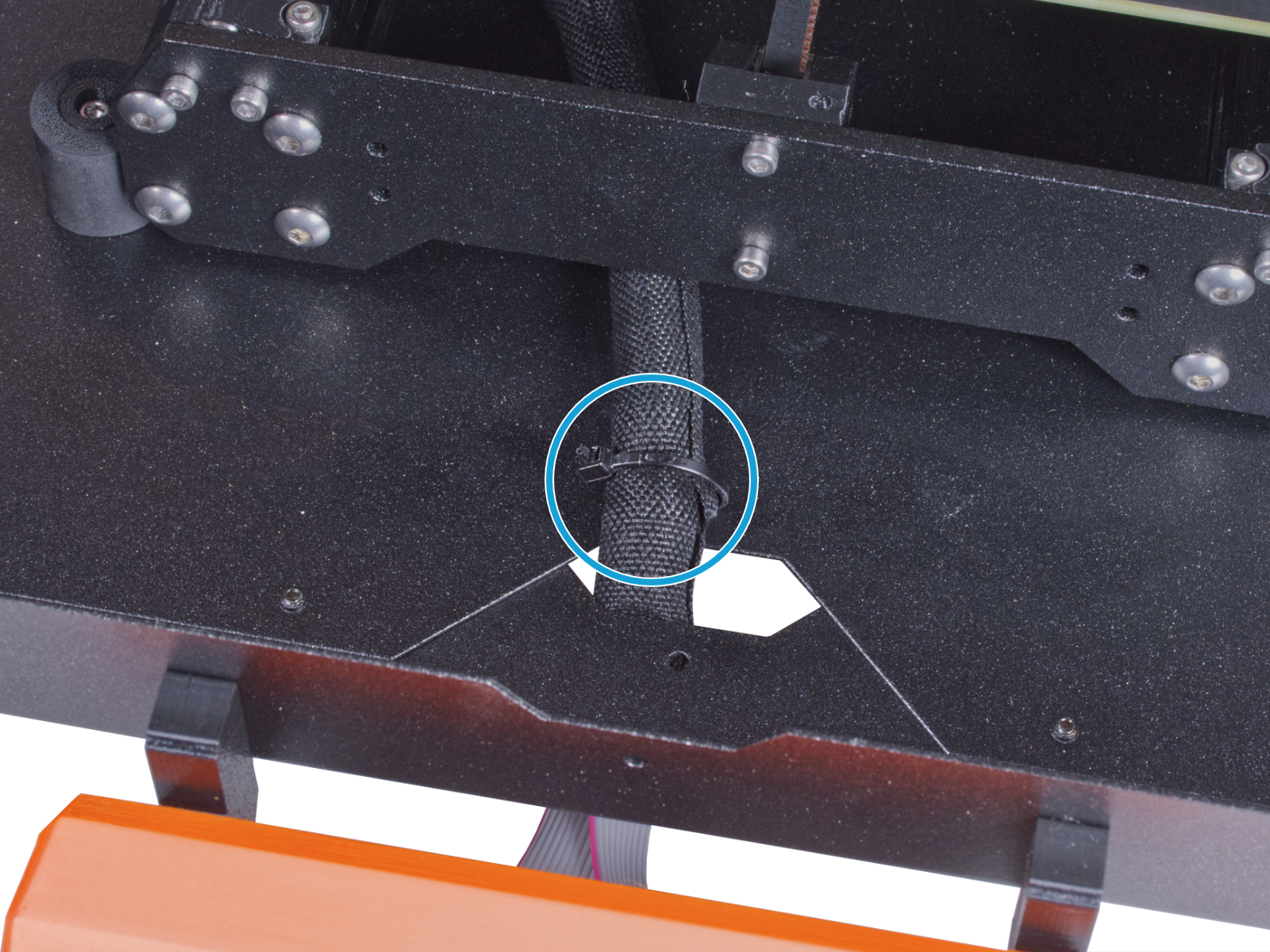
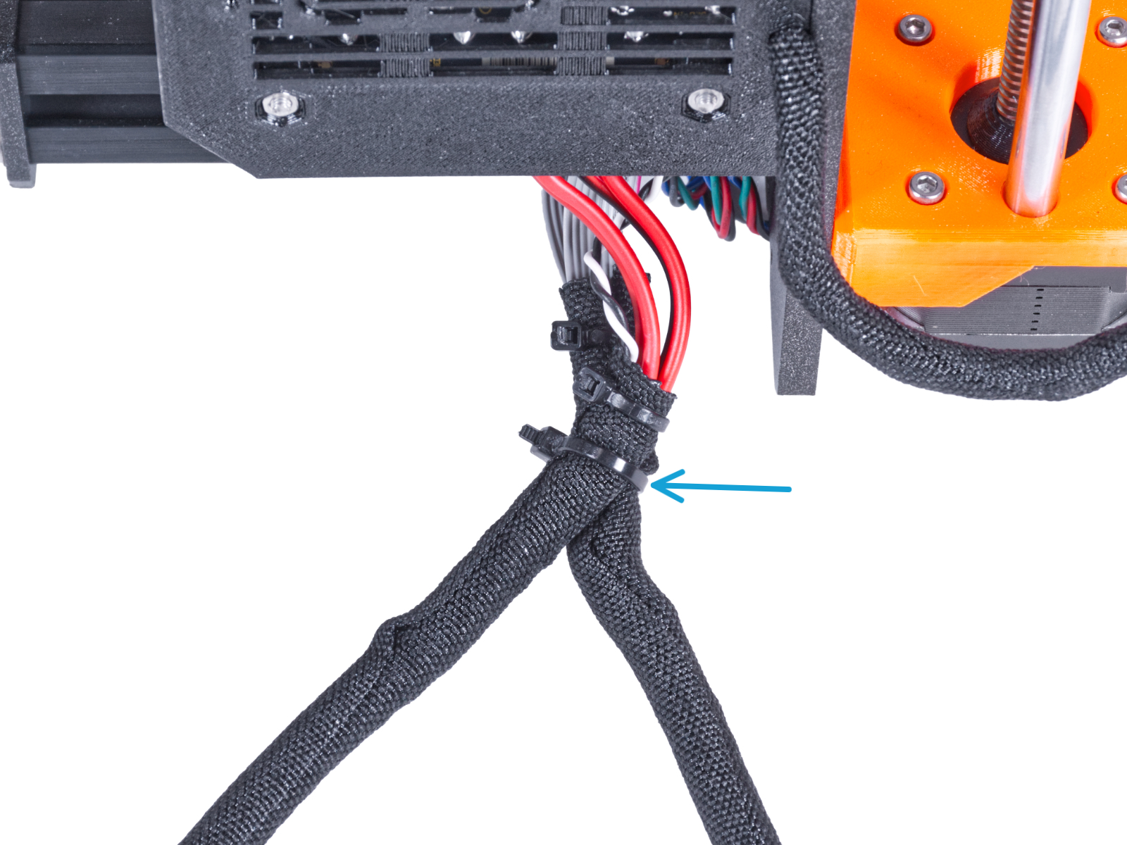
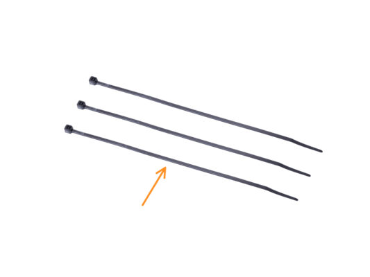
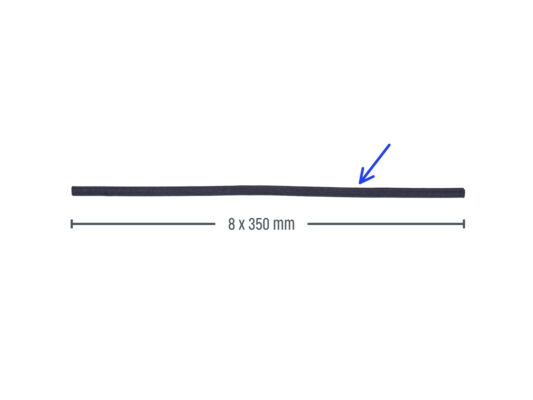
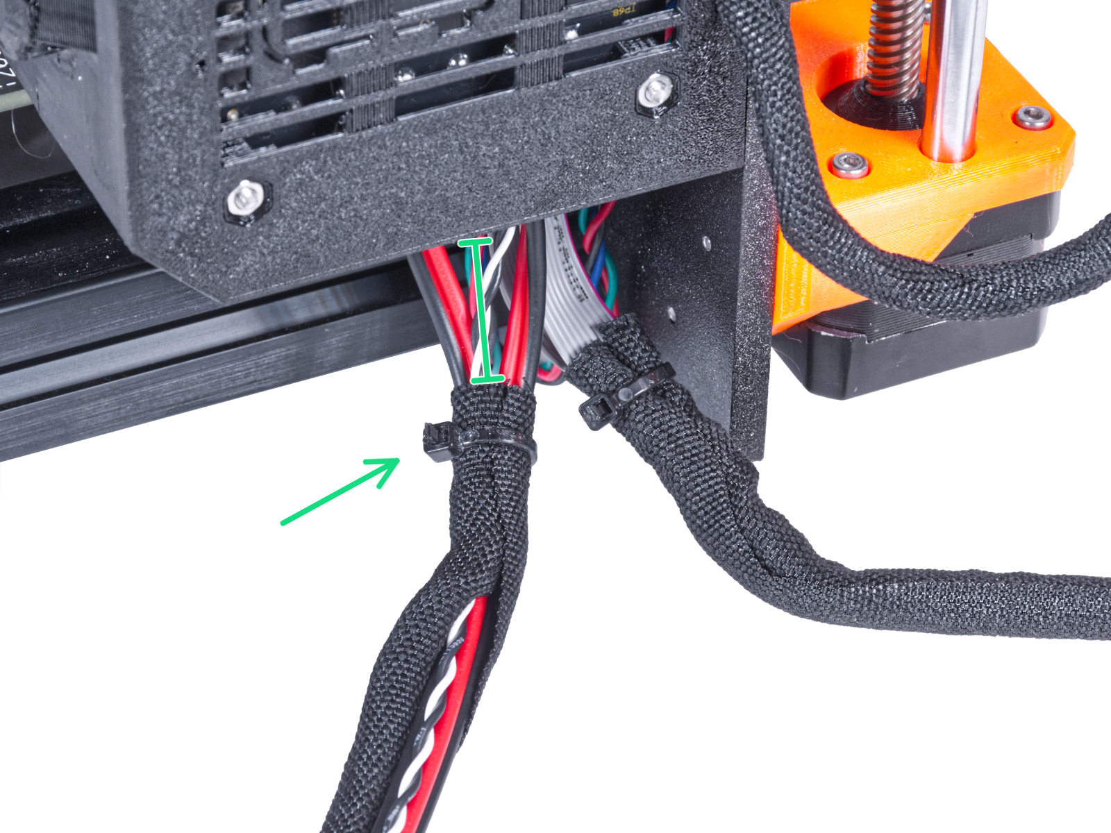
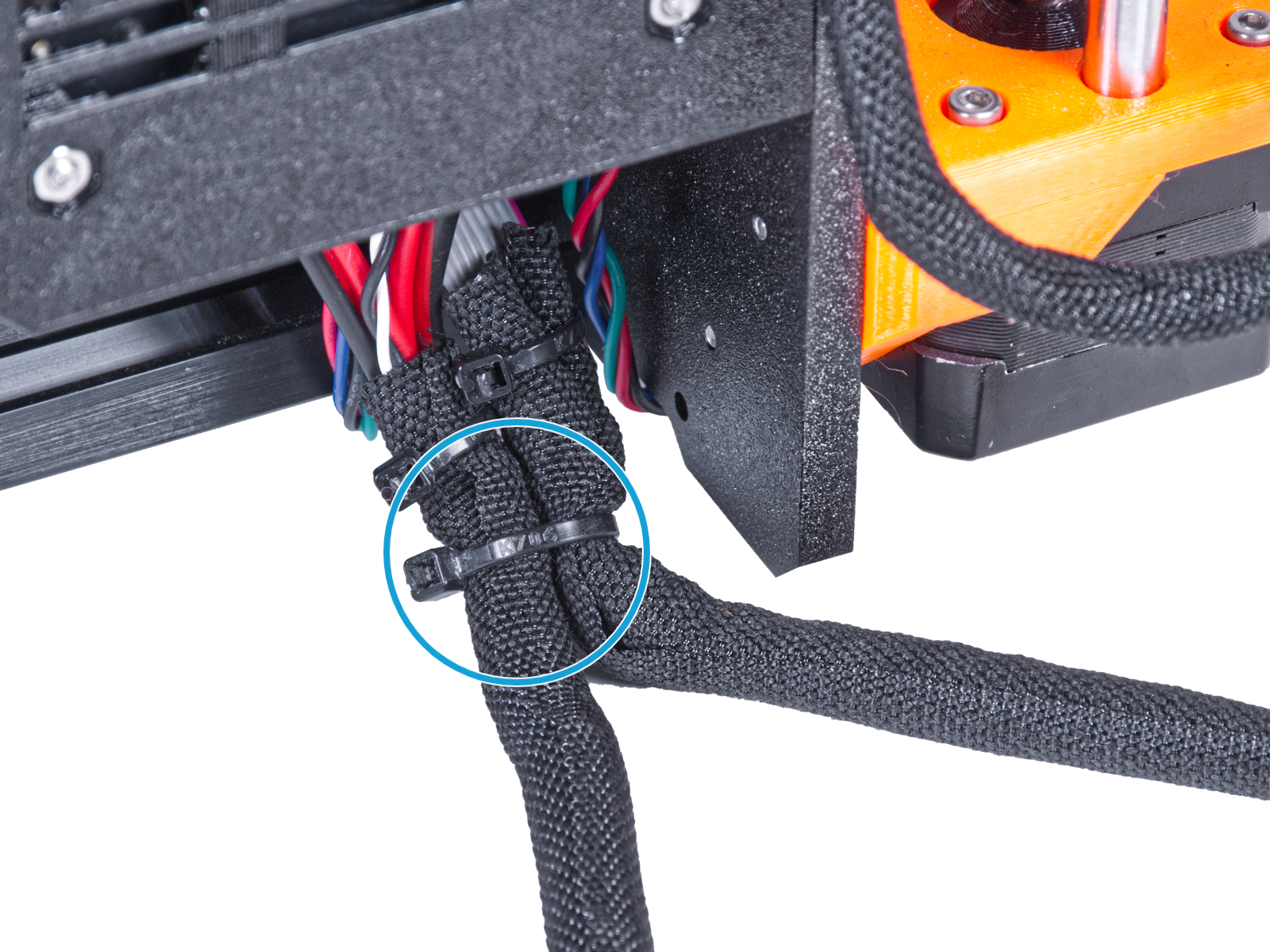
Secure the textile sleeve on the cable bundle with the zip tie. Do not over tighten the zip tie, it may cut the cables!
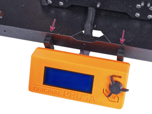
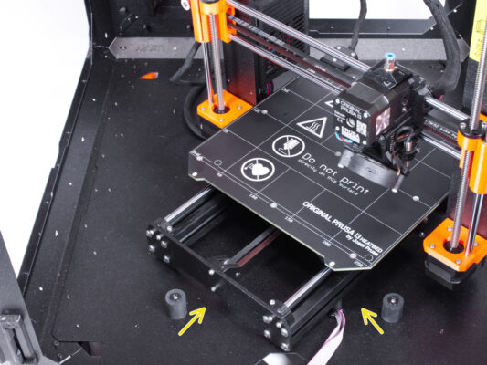
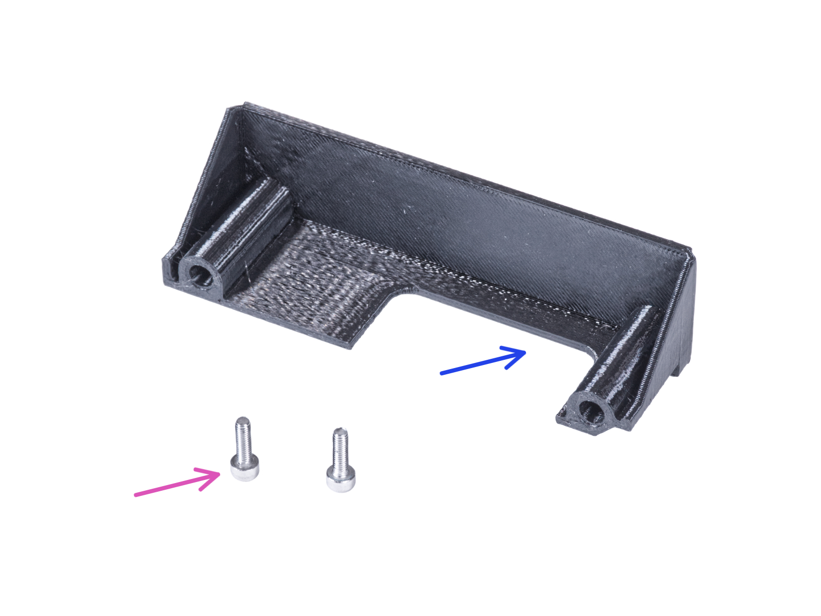
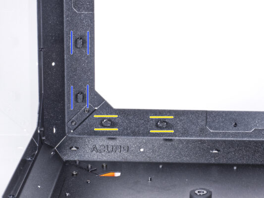
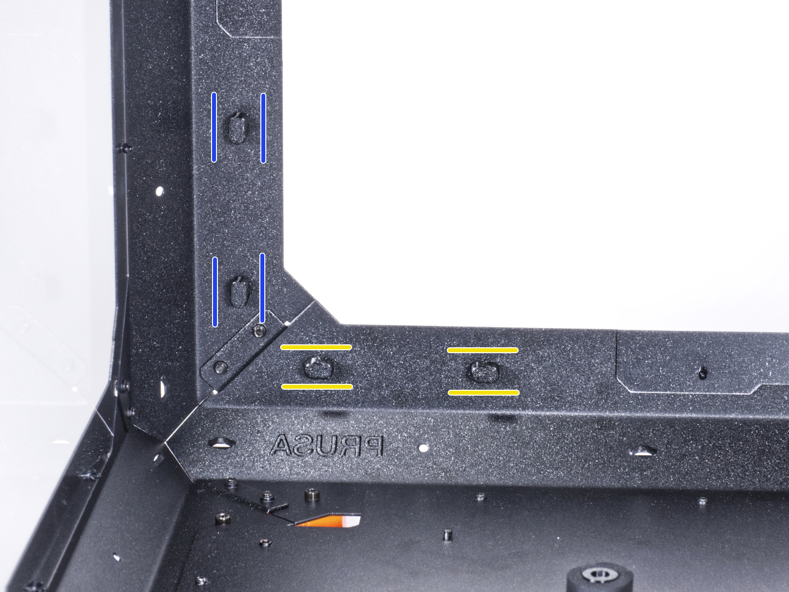
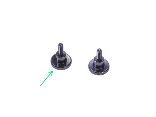
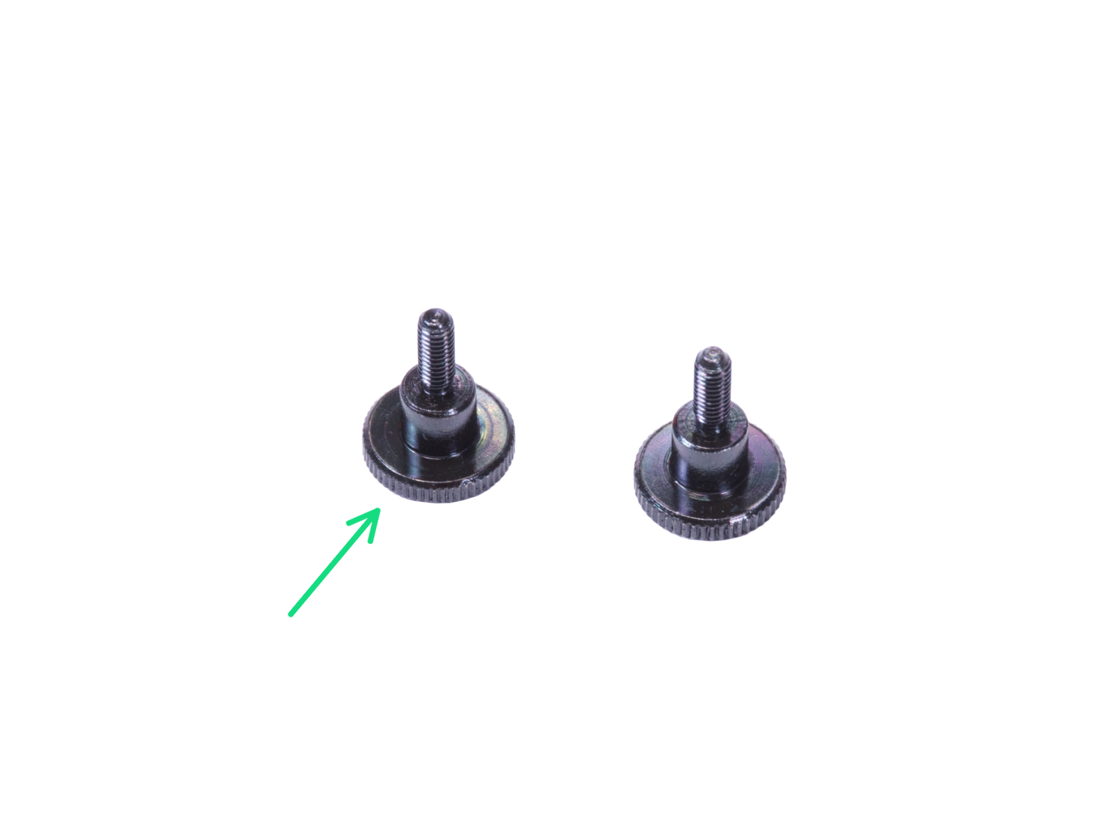
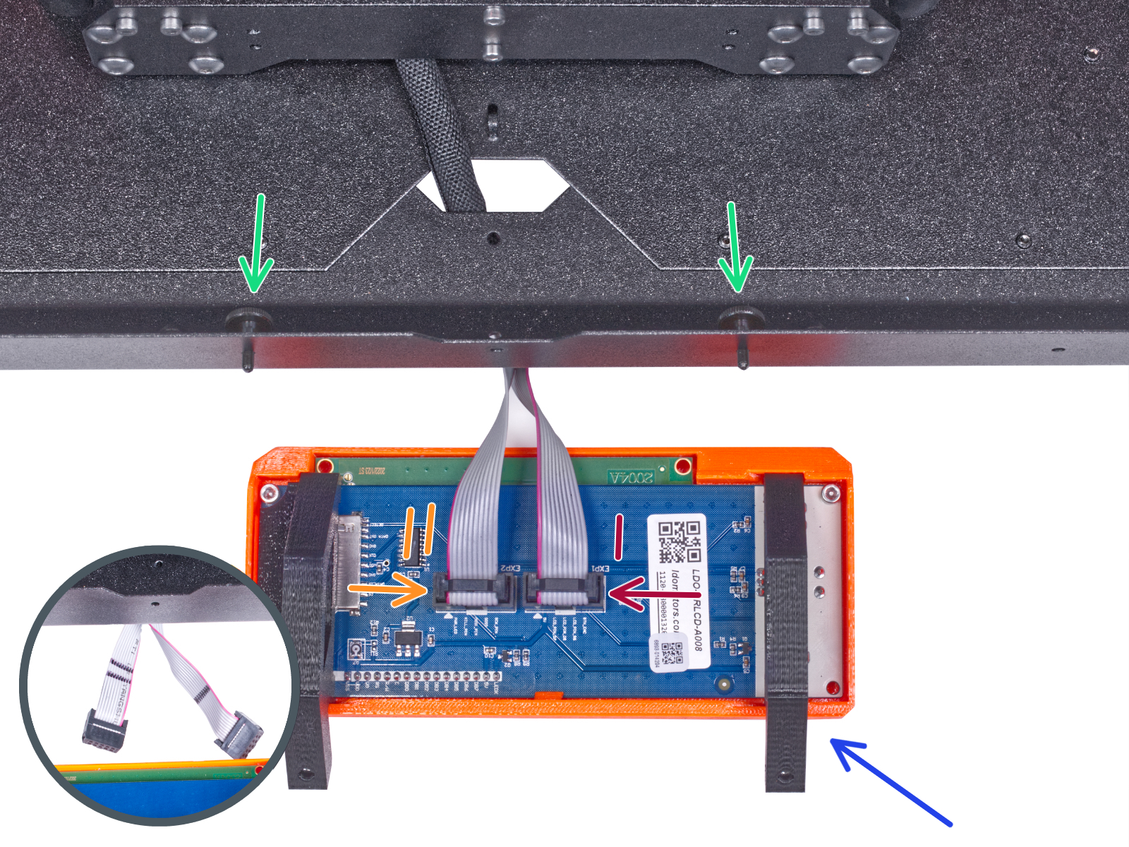
From the inside, push two thumb screws M3x8 through the bottom profile.
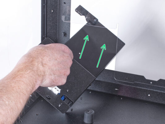
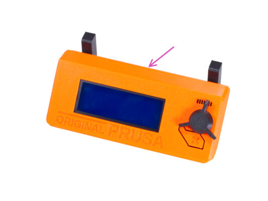
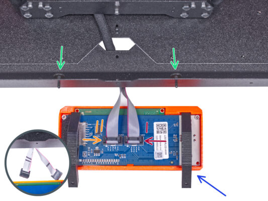
Place the LCD assembly close to the LCD cables, like in the picture. Mind the same orientation of the LCD as in the picture. See the LCD-supports for better understanding.
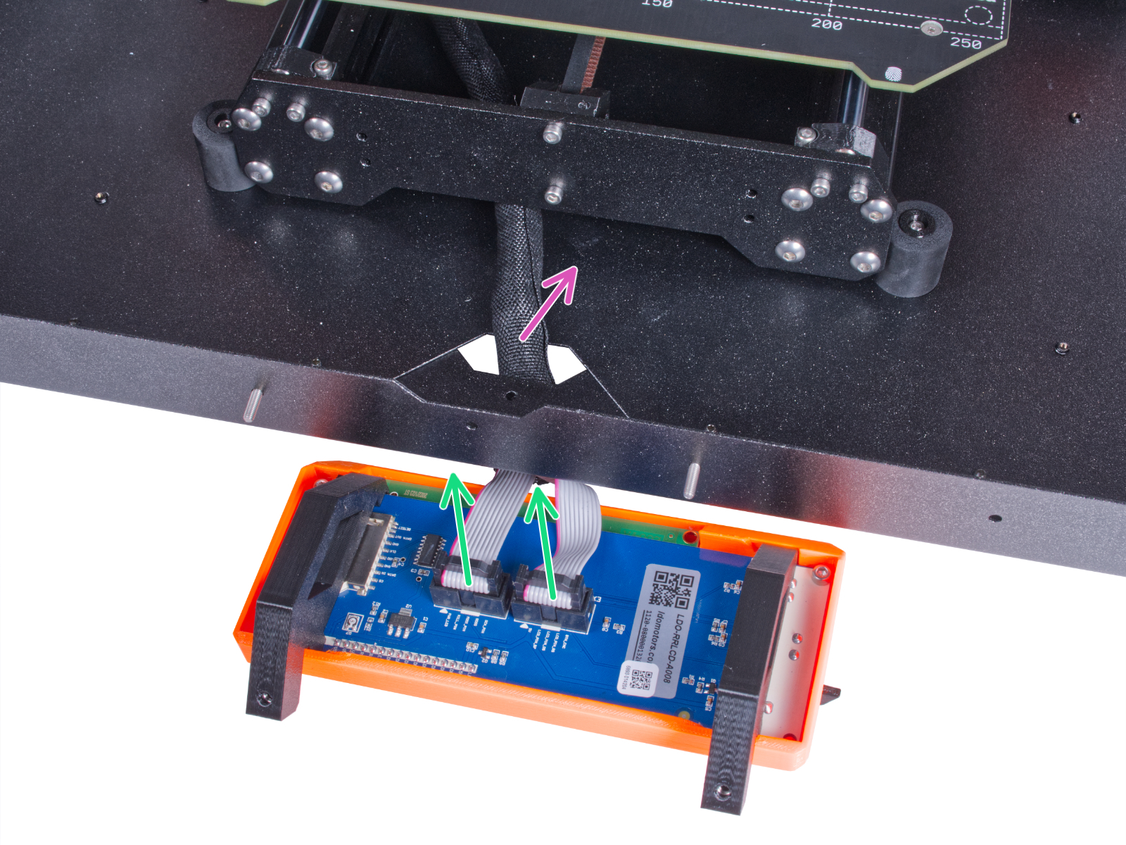
Note that both cables are marked with stripes on one side. Correct connection order is important!
Connect the LCD cable marked with TWO STRIPES to the left slot (called EXP2) on the LCD controller.
Connect the LCD cable marked with ONE STRIPE to the right slot (called EXP1)  on the LCD controller.
Slide the LCD assembly onto the two M3x8 screws in the frame and tighten them.
Well done!
Well done!
Good job! You just successfully installed the quick release cable on the Original Prusa Enclosure.
Was this guide helpful?

Comments

Still have questions?

Still have questions?

If you have a question about something that isn't covered here, check out our additional resources.
And if that doesn't do the trick, you can send an inquiry to [email protected] or through the button below.

Contact us