AA

Doporučené produkty

    Oblíbené kategorie

      Populární vyhledávání

        Články

          Blog

            Produkty

              Kategorie

                Navrhovaná hledání

                  Vyhledávám…
                  Žádné výsledky
                  Něco se pokazilo.
                  ↑↓ Vybrat↵ OtevřítEsc Zavřít hledání
                  • English
                  • Čeština
                  • Deutsch
                  • Español
                  • Français
                  • Italiano
                  • Polski
                  • 日本語
                  • Objednávky
                  • Adresa
                  • Skladové upozornění
                  • Kurzy
                  • Předplatné
                  • Upravit účet
                  • 3D tiskárny9+▾

                    3D tiskárnynovinka

                    novinkaPrusa CORE One L+Zjistit více
                    novinkaPrusa CORE One+ (Gen 2)Zjistit více
                    newPrusa CORE One L+ INDX 8-ToolnovinkaPrusa CORE One+ (Gen 2) INDX 8-ToolPrusa CORE One L+: Critical InfrastructureOriginal Prusa MK4SnovinkaOriginal Prusa XL+Original Prusa XL+: Critical Infrastructure

                    Upgrady tiskáren

                    newCORE One/+ INDX Conversion KitnovinkaCORE One L+ upgradenovinkaPrusa CORE One+ to Prusa CORE One+ (Gen 2)novinkaPrusa XL to Prusa XL+ Upgrade
                    Věrnostní program PrusaDoporučte nás a získejte odměnu
                    Jak si vybrat 3D tiskárnu?Provede vás základy, abychom společně našli tiskárnu, která odpovídá vašemu prostoru, rozpočtu i nápadům.
                    Elektronická kniha zdarmaStáhněte si zdarma elektronickou knihu Základy 3D tisku s Josefem Průšou a vykročte do světa 3D tisku.
                    Tisknutelné části tiskáren Original PrusaKolekce tisknutelných náhradních dílů pro tiskárny Original Prusa a jejich upgrady.
                    Informace o dodacích lhůtáchPravidelně aktualizované informace o výrobních kapacitách a dodacích lhůtách našich tiskáren.
                    Zakázkový 3D tiskProfesionální zakázkový 3D tisk z různých materiálů dle vašich požadavků.
                  • Materiály▾

                    Filamenty

                    PrusamentPLAPETGASA / ABSPC (Polykarbonát)PA (Nylon)FlexKompozitní materiálySpeciální materiályVýprodej Materiálů

                    Resiny

                    ResinResin Cleaner
                    Průvodce filamentyZkontroluj svou cívku Prusamentu
                    Prusament.com
                  • Díly & příslušenství▾

                    Příslušenství

                    EnclosureTryskyTiskové plátyZákladní příslušenstvíKamery a doplňkyNářadí a CraftingLepidla

                    Náhradní díly

                    Merch

                    Náhradní díly - všechny tiskárnyCORE OneMK4/S a MK3.9/SMK3/MK3S/MK3S+XL
                    Merch
                  • Pro firmy▾
                    Prusa Pro HT90Prusa Pro SLXPrusa Pro AFSPrusa Pro Medical OneOriginal Prusa XLOriginal Prusa XL: Critical Infrastructure
                    Prusa CORE One+Zjistit více
                    Prusa CORE One LZjistit více
                    Prusa CORE One L: Critical Infrastructure Edition

                    Využití 3D tisku

                    Výroba a vývojAutomobilový průmyslZdravotnictvíVzdělávání a výzkumArchitektura a designFilmový průmyslKritická Infrastruktura

                    3D tiskařské příběhy

                    • Jak začal 3D tisk: o RepRapu a open-source s Adrianem Bowyerem
                    • Jak 3D tisk mění výuku matematiky na univerzitě v rakouském Linci
                    • Jak pomocí 3D tisku vznikal šroubovák LTT
                    • Victoria Hand Project: Jak 3D tisk mění protetiku
                    Oficiální prodejci Prusa
                    Udržitelnost
                    Prusa Education
                    Kontakt a poptávky
                    Zakázkový 3D tisk
                    Certifikace ISO
                  • Software▾
                    PrusaSlicer

                    PrusaSlicerPrusaSlicer

                    PrusaSlicer je open-source software plný užitečných funkcí s častými aktualizacemi. Obsahuje vše, co potřebujete k exportu dokonalých tiskových souborů pro vaši 3D tiskárnu.

                    WindowsMacOSLinux
                    Prusa Connect

                    Prusa Connect

                    Prusa Connect je snadno nastavitelná cloudová služba pro vzdálené ovládání a monitorování vašich 3D tiskáren, která umožňuje bezpečné nakládání s daty a správu více tiskáren, ať už jste kdekoliv.

                    Přihlásit se do Connectu
                    Aplikace Prusa

                    Aplikace Prusa

                    Ovládejte svou tiskárnu vzdáleně odkudkoliv pomocí technologie Prusa Connect běžící na pozadí. Aplikace Prusa přináší novou úroveň zážitku z tiskáren Prusa na mobilních zařízeních s operačními systémy Android a iOS.

                    Vyzkoušet!
                    Ovladače a firmwareStáhněte si nejnovější firmware a ovladače pro svou 3D tiskárnu.
                    Podpora k PrusaSliceru
                    Podpora k Prusa Connectu
                  • 3D modely▾
                    3D tiskárnyUmění & designKutilství & koníčkyDomácnostMiniatury do stolních herHry & hračkyObchod na Printables

                    Oblíbené 3D modely

                    • Strong garden hose holder
                    • Prusa Spool Bot
                    • Build Tray — Modular Organizer for Assembly, Disassembly and Maintenance
                    • Broom Holder
                    • Octagon Fabric
                    • Prusa CORE One ? (Mimic Skin)

                    Designové soutěže

                    • Framework Laptop 12 Mainboard Re-Use1. 9. 2026 – 30. 9. 2026
                    • 🏆 Designer Challenge: Magic tricks!1. 9. 2026 – 22. 9. 2026
                    • Prototype to Product: Camera Accessories1. 8. 2026 – 14. 9. 2026
                  • Komunita▾

                    Nadcházející akce

                    • Maker Faire Tokyo 20265. 9. 2026 – 6. 9. 2026 · Tokyo, Japan · Prusa Team
                    • IFA 20264. 9. 2026 – 8. 9. 2026 · Berlin, Germany · Prusa Team
                    • 3D Printopia 202626. 9. 2026 – 27. 9. 2026 · Pennsylvania, United States · Prusa Team
                    • Maker Faire Bay Area25. 9. 2026 – 27. 9. 2026 · Kalifornie, United States · Prusa Team

                    Prusa Forum

                    • 6.8.1 Zamrzání obrazovky
                    • Reklamace tvrzené trysky
                    • Core one - čištění trysky G-kód
                    Mapa Prusa WorldMapa Prusa WorldVyhledejte lokální uživatele 3D tiskáren a prozkoumejte komunitu kolem sebe
                  • Podpora▾
                    Manuály & návodyPrusaSlicerPrusa ConnectMateriály

                    Model tiskárny

                    CORE One INDXCORE One LCORE One+CORE One

                    Řešení problémů s hardwarem

                    • Selftest selhal (CORE One/+)
                    • Ucpaná tryska (CORE One, CORE One L, XL, MK4/S, MK3.9/S)
                    • Úprava napnutí řemenů (CORE One/+, CORE One INDX, CORE One L/+)
                    • Co jsou PrusaLink a PrusaConnect

                    Ovladače a firmware

                    Rodina INDXRodina CORE OneRodina MK4Rodina XLRodina MMURodina PRO
                  • Kurzy▾

                    Staňte se expertem na 3D tisk

                    Prusa Academy nabízí online kurzy na nejrůznější témata týkající se 3D tisku. Každý kurz obsahuje:

                    • srozumitelný text s mnoha obrázky a krátkými videi
                    • odkazy pro inspiraci a další studium
                    • kvízy pro ověření vašich znalostí
                    • certifikát o dokončení
                    Procházet všechny kurzy"Moje knihovna kurzů
                    • 3D modelování v Autodesk Fusion
                    • PrusaSlicer Masterclass – Pro začátečníky až pokročilé
                    • Kompletní průvodce postprocesováním a barvením 3D výtisků
                    • Airbrush Your 3D Prints: From Basics to Advanced Tricks
                  • Blog▾
                    • Akce Zpátky do školy 2026 je tady!
                    • PrusaSlicer 3.0 Preview – Vše je připraveno na budoucnost 3D tisku
                    • Prusa CORE One+ (Gen 2) INDX, odesílání prvních kusů a objednávky kompletních tiskáren
                    E-book Základy 3D tisku
                  • O nás▾

                    Volná místa

                    • Commercial Operations specialista/ka
                    • Operátor/ka expedice filamentů
                    • Obsluha elektroerozivního obráběcího stroje - hloubičky - PD Tool
                    • Operátor/ka výroby průmyslových 3D tiskáren v Hradci Králové

                    O Prusa Research

                    Jsme největším výrobcem 3D tiskáren v Evropě a Spojených státech. Společnost byla založena v roce 2012 nadšencem, kutilem a vynálezcem Josefem Průšou. Během pouhých 15 let jsme vyrostli ve společnost s více než 1200 zaměstnanci. Každý měsíc navrhujeme, vyrábíme a odesíláme přes 10 000 inovativních a zabezpečených 3D tiskáren z naší centrály v Praze a pobočky v americkém Delaware do více než 160 zemí světa. Podívejte se na video, ve kterém se dozvíte, jak firma Prusa Research vznikla a čeho jsme dosáhli během pouhých 10 let!

                    O násČasová osaUdržitelnostOpen-source
                    O nás
                    Kontaktujte nás
                    Logo a fotografie
                    Průša pro školy
                    Volná místa
                    Certifikace ISO
                  1. Podpora
                  2. Original Prusa MK3.5
                  3. Vlastnosti tiskárny
                  4. GPIO Modul
                   

                  Obsah

                  • Use-case ideas
                  • Safety first!
                  • Schematics
                  • How to install the GPIO board
                  • Pins
                  • Pull-up resistors
                  • Understanding pin values
                  • Setting GPIO via Custom G-Code
                  • How to Set Up G-code for Input Pins
                  • Advanced Input Control and Macro Triggering
                  • Custom G-Code in Prusa Slicer
                  • Examples

                  Blog

                  • Akce Zpátky do školy 2026 je tady!
                  • PrusaSlicer 3.0 Preview – Vše je připraveno na budoucnost 3D tisku
                  • Prusa CORE One+ (Gen 2) INDX, odesílání prvních kusů a objednávky kompletních tiskáren

                  Novinky e-mailem

                  Přihlaste se k odběru našeho měsíčního přehledu užitečných informací o novém firmware, nových verzích PrusaSliceru a zajímavých tipů na 3D tiskařské projekty.

                  Kliknutím udělujete souhlas se zasíláním newsletteru.

                  Tato stránka je chráněna pomocí reCAPTCHA Enterprise a uplatňuje tedy Ochranu osobních údajů a Podmínky použití společnosti Google.

                  Strong garden hose holder
                  E-shop
                  • 3D tiskárny
                  • Upgrady tiskáren
                  • Filamenty
                  • Příslušenství
                  • Prusa Merch

                  © Prusa Research a.s.

                  Printables
                  • 3D modely
                  • Store
                  • Clubs
                  • Designerské soutěže
                  • Brands
                  Komunita
                  • Mapa světa
                  • Fórum
                  • Uživatelské skupiny
                  • Výstavy a akce
                  Podpora
                  • Prusa Help
                  • Prusa Academy
                  • Kalkulačky
                  Software
                  • PrusaSlicer
                  • Prusa.app
                  • Prusa Connect
                  • Ovladače a software
                  Firma
                  • O nás
                  • Blog
                  • Oficiální prodejci Prusa
                  • Kontakty
                  • Certifikováno podle norem ISO 9001, ISO 14001 a ISO 45001
                  • Volná místa
                  • Všeobecné obchodní podmínky
                  • Obecné podmínky používání internetových stránek PRUSA
                  • Zásady ochrany soukromí
                  • Informace o cookies
                  • Proces řešení stížností zákazníků
                  • Stavová stránka webu
                  • Nastavení cookies
                  • Recyklace 3D tiskárny
                  • Všeobecné obchodní podmínky
                  • Obecné podmínky používání internetových stránek PRUSA
                  • Zásady ochrany soukromí
                  • Informace o cookies
                  • Proces řešení stížností zákazníků
                  • Stavová stránka webu
                  • Nastavení cookies
                  • Recyklace 3D tiskárny

                  © Prusa Research a.s.

                  JOSEF PRUSA®, PRUSA RESEARCH®, PRUSA POLYMERS®, PRUSA ORANGE®, PRUSA 3D ® A PRUSAMENT® jsou registrované ochranné známky společnosti Prusa Development a.s., které používá společnost Prusa Research a.s. na základě licence od společnosti Prusa Development a.s.

                  GPIO Modul

                  Relevantní pro

                  CORE One family
                  MK4 family
                  MK3.5 family
                  MK3.9 family
                  1 komentář
                  Článek Tento článek je také dostupný v následujících jazycích:
                  English
                  Čeština
                  Polski
                  Deutsch
                  Français
                  Español
                  Italiano
                  日本語

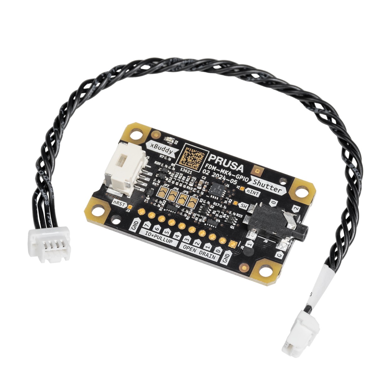
                  The GPIO module (General Purpose Input Output) is an additional, optional PCB that can be connected to the Prusa CORE One/+, and to the Original Prusa MK4/S, MK3.9/S, or MK3.5/S.

                  IMPORTANT: To utilize the full potential of the GPIO board you need firmware 6.2.0-alpha1 or newer. Visit the GitHub to download the latest firmware. 

                  The module provides expanded functionality by allowing the control of external devices through connections to the GPIO board pins, which can operate in either INPUT or OUTPUT mode. This versatility opens up a wide range of potential use cases.

                  Share and discuss your projects with the other members of the Prusa Community on our official forum. We have created a dedicated GPIO section.
                  Use-case ideas

                  The module can control a camera shutter at a precise moment, making it ideal for creating visually perfect time-lapses, where each picture is captured at the exact same point in time.

                  Beyond controlling a camera shutter, the module can be used for various other applications. For example, it can trigger external lighting to illuminate the print area at specific stages of the printing process, ensuring optimal lighting conditions for quality checks or photography. Additionally, it can be configured to activate cooling fans or other peripheral devices, such as extractors or alarms, based on custom G-Code execution during prints, helping maintain optimal operating conditions and improving the safety and efficiency of the 3D printing environment.

                  Another powerful use case is the integration of a macro keyboard, where each keypress can trigger the execution of specific G-Code commands. This setup allows for rapid manual control of the printer's functions, such as starting or pausing a print, adjusting temperatures, or moving the print head to an exact position. The ability to trigger custom actions with a simple keypress can significantly streamline workflows, making the GPIO expansion module a versatile and indispensable tool for those looking to fully customize and optimize their 3D printing setup.

                  Safety first! 

                  While the ability to trigger G-Code via GPIO inputs adds great flexibility, it also comes with limitations and potential risks. Improper use or poorly timed G-Code commands can interfere with the printing process, leading to print failures or even damage to the printer. It’s crucial to thoroughly test any custom G-Code setups in a controlled environment before deploying them in actual print jobs to avoid unintended consequences.

                  Additionally, we recommend that only experienced users with a solid understanding of electronics and G-Code manipulation utilize this GPIO module, as improper connections or configurations can result in hardware damage or safety hazards.

                  Schematics 

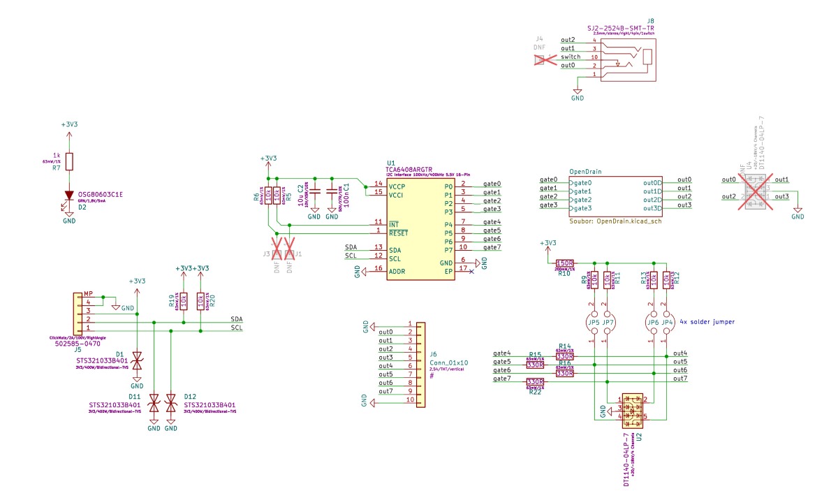
                  The schematics are open source, and available on our page Open Source at Prusa Research. 
                  How to install the GPIO board

                  1. Ensure the printer is cooled down to room temperature, and switch it off.
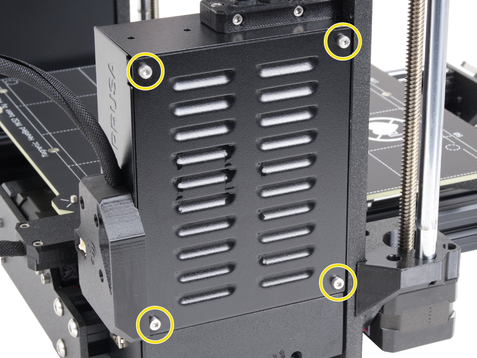
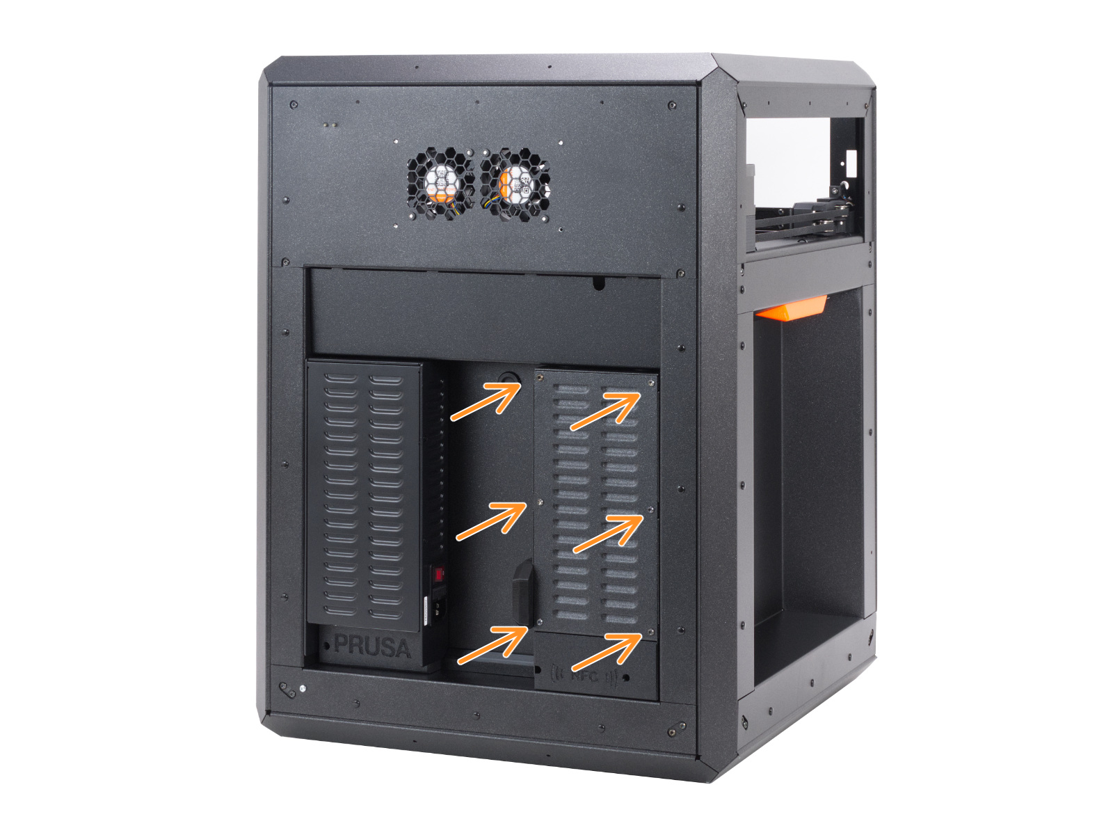
                  2. Open the xBuddy box cover by removing four M3x6 screws (MK-series), by removing six M3x4bT bolts (CORE One). 
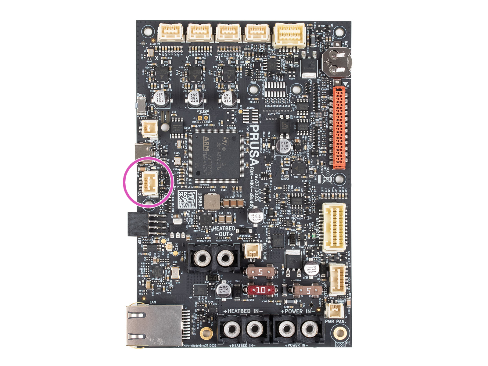
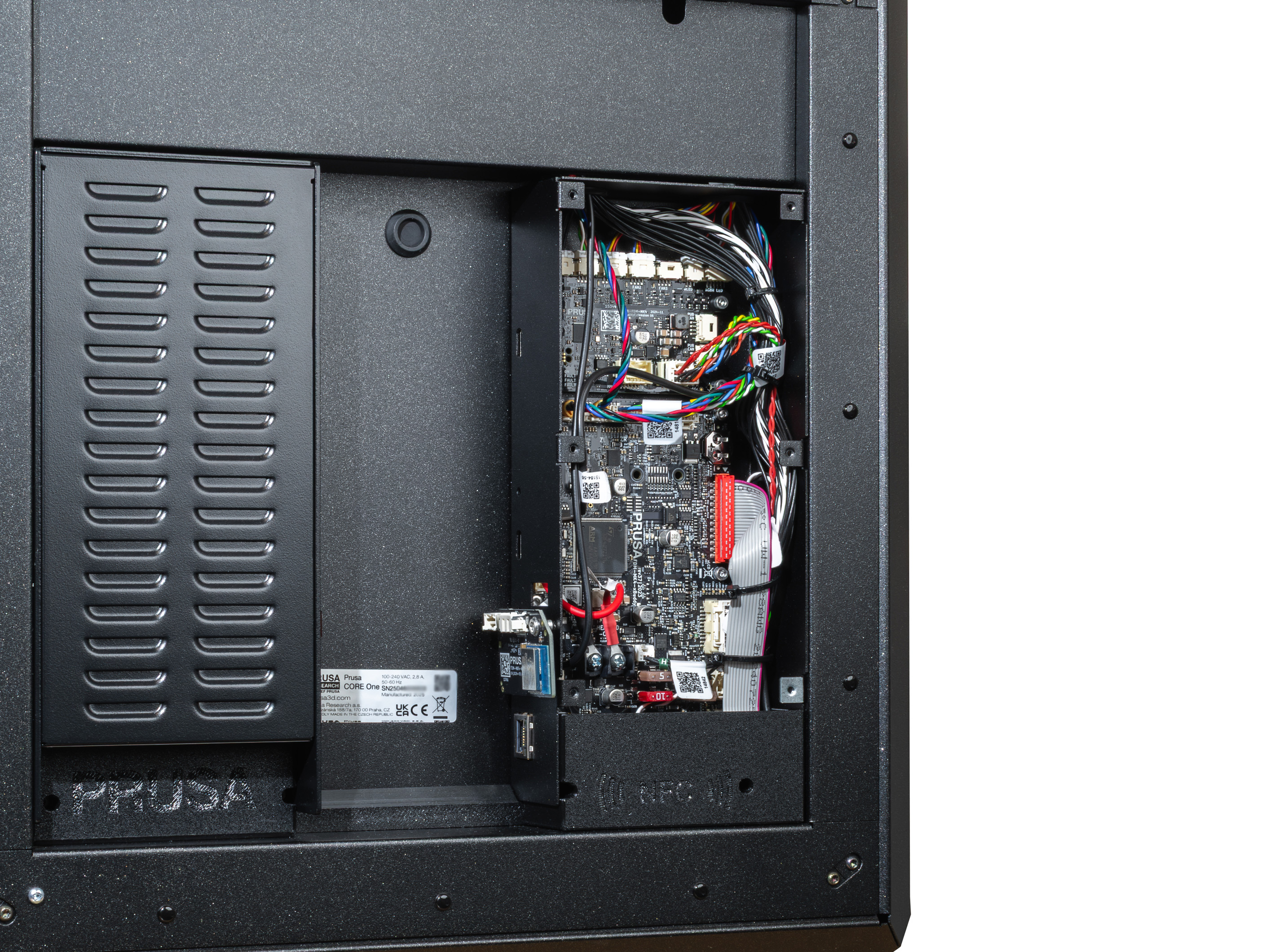
                  3. Connect the GPIO cable to the I2C port.
                  4. Close the xBuddy box cover.
                  5. Ensure that the GPIO does not touch any metal parts of the xBuddy box or its cover. 
                  6. Enjoy your project!

                  Pins

                  Limits - output mode

                  PIN 0 to 3 -> switch max. 24V, 500mA (to ground)
                  PIN 4 to 7 -> switch 0V or max. 3.3V, 10mA

                  Limits - input mode

                  PIN 4 to 7 -> 0V or 3.3V (max short-circuit current: 0.5mA with < 4 kΩ resistance).

                  Description

                  The board features 8 pins, numbered 0-7. Pins 0-3 can be used as output, and pins 4-7 can function as either input or output. Each pin is of the open-drain type when used as an output, meaning it is controlled by a transistor that connects the pin to the ground (0 V) when active. When the pin is inactive, it remains "floating", which means it is not connected to any specific voltage, but due to internal pull-up resistors, the voltage on the pin can hover around 3.3 V. 

                  It is possible to solder external pull-up resistors to the JP pins. This changes the behavior described above. For more details on that, see the pull-up resistors paragraph below. 

                  The behavior of the pins in an open-drain state when used as outputs can be explained as follows:

                  • Pin set to 0 (LOW): The pin is turned off and is in a "floating" state, which means it is not connected to any specific voltage. In this state, the voltage on the pin can fluctuate and is not well-defined unless stabilized by a pull-up resistor.

                  This "floating" state may cause the pin to pick up random electrical noise or interference, leading to unintended behavior if not properly managed. 

                  • Pin set to 1 (HIGH): The pin is turned on and connected to the ground (0 V), causing the voltage on the pin to drop to 0 V. This state is clear and does not lead to any ambiguity in signal detection.

                  When the pins are used as inputs, they can detect the voltage level applied to them. The input state is influenced by the presence of pull-up resistors, which can help ensure a consistently high voltage (3.3 V) when no other voltage source is applied.

                  Pull-up resistors

                  The board allows the connection of external pull-up resistors via solder jumpers labeled JP4 to JP7. These solder jumpers are located in the center of the board and are connected to the corresponding pins:

                  • JP4 is connected to Pin 4
                  • JP5 is connected to Pin 5
                  • JP6 is connected to Pin 6
                  • JP7 is connected to Pin 7

                  Solder jumpers JP7 to JP4 can be used to connect integrated pull-up resistors, which ensures that the pins remain at a high voltage (3.3 V) when not actively driven low by an external source or by the pin's output state. These pull-up resistors have a value of 10K ohms, which is a standard value to provide stable voltage without excessive current draw.

                  If the jumper is not soldered, the pin may remain in a floating state, potentially leading to unstable behavior. JP stands for "jumper": if the jumper is not soldered, the stabilizing 10 kOhms resistor is not connected to the gate and its signal. 

                  For less experienced users, it's important to understand that open-drain outputs do not inherently produce a high voltage (3.3 V) but rather allow a connection to ground (0 V). Pull-up resistors are necessary to ensure that the pin remains at a high voltage when turned off or when used as an input. If not properly managed, a "floating" voltage can cause the pin to pick up electrical noise, leading to unwanted switching or system instability.

                  Understanding pin values

                  To use advanced registers or read multiple pins at once, the board uses a binary-to-decimal system. Each pin has a unique numerical "weight." To target multiple pins, add their weights together.

                  Pin01234567
                  Weight1248163264128
                  • Example: if you want to use Pin 0 and Pin 1, the value is 1 + 2 = 3
                  • Example: to set all pins (0-7) at once, the value is 255

                  Setting GPIO via Custom G-Code

                  General Information

                  The following is a sequence of custom G-Code commands used for controlling the GPIO board. This allows you to configure output states, read input states, and manage other advanced settings on the board through G-Code instructions, integrating them seamlessly with your 3D printer’s workflow.

                  Pin control via G-Code

                  To control the output pins on the GPIO board, you can use the following G-Code commands:

                  1. Set Pin Mode (Output or Input)
                    • P<0-7>: Select the pin number to configure (from 0 to 7).
                    • B<0 or 1>: Set the pin mode.
                      • 0 - configures the pin as an output
                      • 1 - configures it as an input.
                    • Example: M262 P0 B0 - Configures pin 0 as an output pin.
                       
                  2. Write state to an Output Pin
                    • P<0-7>: Select the pin number to write to (from 0 to 7).
                    • B<0 or 1>: Write 0 to set the pin to LOW (0 V) or 1 to set the pin to HIGH (3.3 V).
                    • Example: M264 P0 B1 - Sets output pin 0 to HIGH (1).
                       
                  3. Toggle state of Output Pin
                    • P<0-7>: Select the pin number to toggle (from 0 to 7).
                    • This command flips the current state of the selected pin.
                    • Example: M265 P0 - Toggles pin 0.
                       When using M267, the R parameter selects the "folder," and the B parameter provides the pin map:
                  4. Advanced Register Setup (For Experienced Users)

                  When using M267, the R parameter selects the "folder," and the B parameter provides the pin map:

                    • R<1-3>: Select the register to configure:
                      • 1: Output Register. Sets the voltage for output pins. 0 = Low (0V), 1 = High (3.3V).
                      • 2: Polarity Register. Defines logic. 0 = Normal, 1 = Inverted. Useful for preventing "ghost" triggers on pins 0-3.
                      • 3: Configuration Register. Defines direction. 0 = Output, 1 = Input. (e.g., B255 makes all pins inputs).
                    • B<0-255>: Set the value to be written to the selected register.
                    • Example: M267 R3 B255 - Configures the Configuration Register with the value 255 (all pins set to inputs).

                  To read the state of pins or set up configurations, use the following G-Code commands:

                  1. Read state of Pin
                    • P<0-7>: Select the pin number to read from (from 0 to 7).
                    • The returned value will indicate whether the pin is HIGH (1) or LOW (0).
                    • Example: M263 P6 - Reads the state of pin 6 (returns 32 for HIGH or 0 for LOW).
                       
                  2. Read Entire Input Register
                    • This command reads the entire input register, returning a number in given "style" format that represents the states of all input pins (from 0 to 7).
                    • Possible states are:
                      • 1 - HEX DUMP
                      • 2 - signed two byte integer, base 10 (int16)
                      • 3 - unsigned byte, base 10 (uint8)
                    • device address is always 32
                    • Example: M261 A32 B1 S3 - reads the entire input register and returns it as unsigned byte base 10
                       
                  3. Read IO expander's register (For Experienced Users)
                    • this reads the whole byte of the given register at once
                    • R<0-3>:
                      • 0 - Input
                      • 1 - Output
                      • 2 - Polarity
                      • 3 - Config
                    • Example: M268 R3 - Reads Config register

                  Interpreting Read Results

                  When you read a register (M268) or the entire input (M261), the printer returns a single number. Use the weight table to decode it. 

                  Note on M261: This command is for communicating with external I2C "Slave" devices connected to the board. Address 32 is the GPIO board itself; other addresses depend on the specific hardware you attach.
                  Pin01234567
                  Weight1248163264128

                  Examples

                  • If M268 R0 returns 64, Pin 6 is active.
                  • If it returns 192, then both Pin 6 (64) and Pin 7 (128) are active (64+128=192).

                  How to Set Up G-code for Input Pins

                  To configure input pins for your setup, each input pin is automatically mapped to a specific G-code file located on the USB drive. These files must be stored in a folder named "macros" and follow a strict naming convention: the file name must be in the format

                  where {pin_number} corresponds to the specific GPIO pin you are using. All letters in the file names must be lowercase.

                  For example:

                  • if you are using pin 7, the corresponding G-code file must be named btn_7.gcode and placed in the "macros" folder.
                  • similarly, for pin 4, the file should be named btn_4.gcode

                  The system supports 8 input pins on the GPIO board, and each pin can be mapped to a unique G-code file in this way.

                  When a G-code file is triggered via its corresponding input pin, the G-code stored in that file is immediately injected into the ongoing process. Please note that there is a size limit for each G-code file, which must not exceed 1024 bytes.

                  While the naming convention (btn_x.gcode) is fixed, the content of the file is limited only by the Prusa firmware.

                  You can inject any valid G-code. This includes M600 (filament change), M112 (emergency stop), M104 (temperature changes), or G28 (homing).
                  Limitations: Macros are injected into the current command stream. The system does not currently support software-based triggers (e.g., "run macro when print finishes"); triggers are strictly physical via the input pins.

                  Advanced Input Control and Macro Triggering

                  When an input pin is configured using M262 and set to 1 (input mode), the state of the pin is periodically checked every 0.5 seconds.

                  If a button connected to the pin is pressed (pin state goes LOW), it triggers a macro button. For example, a button on pin 7 can automatically execute a macro stored in the file macros/btn_7.gcode on a USB drive. The macro is injected into the print sequence, with a size limit of 1024 bytes.

                  Persistent Memory

                  Configuration of the pins and their states are stored in EEPROM, ensuring that pin settings (output/input modes, polarity, and states) are preserved even after a power cycle.
                  Changes made via M262, M264, M267, or any other relevant G-Code will update the EEPROM, so the settings are persistent.

                  Edge Cases

                  For pins 0-3, which lack internal pull-up resistors, configuring them as input without additional external circuitry may result in an inverted logic state. This can inadvertently trigger macro execution due to their default idle state being LOW (0).

                  You can invert the logic of input pins using the Polarity Register (M267 R2 B<value>). This feature is particularly useful for pins that do not have pull-up resistors (pins 0-3), which default to an idle state of 0 (LOW) and might trigger unwanted actions when left unconfigured.

                  All pins (0-7) support polarity inversion equally. This means you can invert the logic for any pin, which is configured as input.

                  The primary difference in behavior between the pins comes from the fact that pins 4-7 can utilize internal pull-up resistors, which hold them at a HIGH state (3.3 V) when not actively driven LOW. However, these pull-up resistors are only active if the corresponding solder jumpers (JP4 to JP7) are connected. If these jumpers are not soldered, pins 4-7 behave similarly to pins 0-3, defaulting to a floating state.

                  When using input pins to trigger macros, the system is designed to detect a LOW state as indicating a pressed button. For pins without active pull-up resistors, this default LOW state can inadvertently trigger macros unless polarity inversion is used.

                  Warnings and Limitations

                  When configuring or writing to pins, the system outputs a warning via the serial port if there is a mismatch between the intended operation (e.g., trying to write to an input pin). It is essential to correctly configure pins using M262 to avoid such conflicts.

                  Custom G-Code in Prusa Slicer

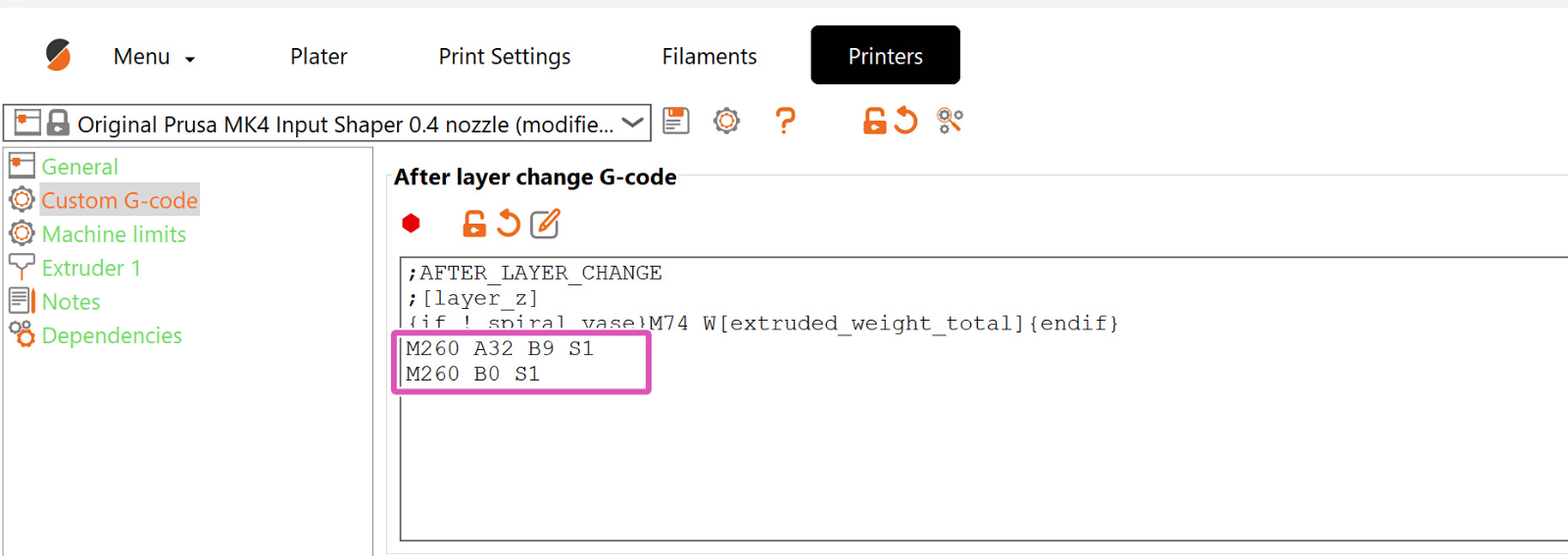
                  Insert the code in the exact spots where it is needed, after/before another particular G-Code command. In the example screenshot, the custom G-Code that controls the GPIO board is set through PrusaSlicer and is positioned after each layer change. However, it can be positioned at any point. 
                  Examples

                  Sample Connection of GPIO Module to Addon Controller (Fan Filter and LED)

                  In the image attached below, we can see the connection between the GPIO module and the addon controller responsible for controlling the Original Prusa Enclosure's fan filter and LED. 
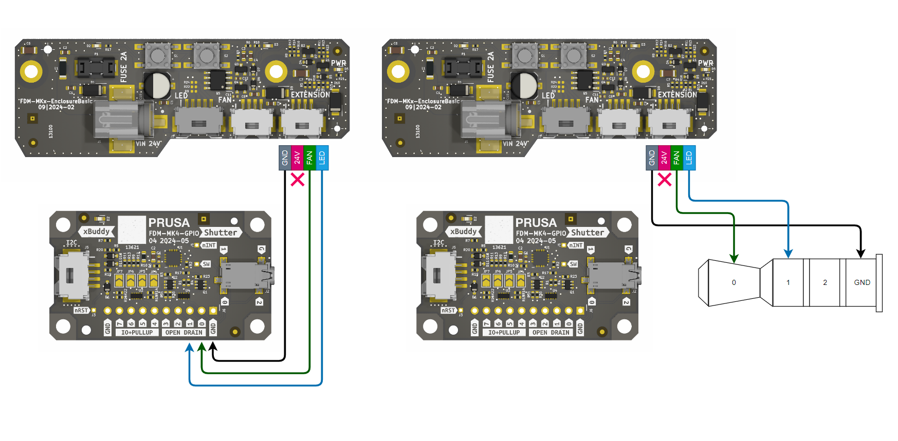
                  We are currently developing a jack-to-molex cable solution for connection between the GPIO board and the EnclosureBasic board. This will provide an easy and user-friendly way to manage the enclosure’s controls.

                  Image of example setup for enclosure

                  Connecting the GPIO board to the Addon Controller allows the printer to automate enclosure features. Example: 

                  Direction: Set the connecting pin (e.g., Pin 0) to output: M262 P0 B0.
                  Automation: In PrusaSlicer, go to Printer Settings > Custom G-code.

                  Start G-code: Add M264 P0 B1 to turn on the enclosure lights/fan when the print begins.
                  End G-code: Add M264 P0 B0 to turn them off when finished.

                  Byl tento článek užitečný?
                  Tato akce je dostupná pouze registrovaným uživatelům. Prosím přihlaste se.

                  1 komentář

                  Pro přidání kometáře se prosím přihlaste 
                  Romhra
                  •
                  není lokalizován do češtiny prosím
                  Reply

                  Témata

                  • O vaší tiskárně
                    • Vlastnosti tiskárny
                      • Profily vyhřívaných podložek
                      • Pružné ocelové pláty (rozcestník)
                      • Tiskové režimy
                      • Senzor filamentu (MK2.5S, MK3S/+, MK3.5/S)
                      • Experimentální nastavení (MK4/S, MK3.9/S, MK3.5/S, XL, MINI/+)
                      • Loadcell (MK4/S, MK3.9, XL)
                      • Vysvětlení významu stavových LED (MK4/XL)
                      • Senzor filamentu na Nextruderu (CORE One, CORE One L, MK4/S, MK3.9/S, XL)
                      • G-cody specifické pro Buddy Firmware
                      • Silikonový návlek Nextruderu (CORE One, CORE One L, XL, MK4/S, MK3.9/S)
                      • Náhled modelu
                      • Zrušit tisk objektu (MK4, MK3.9, XL, MINI/+)
                      • Dotyková obrazovka (CORE One L, CORE One, MK4/S, MK3.9/S, MK3.5/S, XL)
                      • NFC anténa
                      • Akcelerometr (CORE One, MK4/S, MK3.9/S)
                      • GPIO Modul
                      • Připojení k internetu (CORE One L, CORE One, MK4S, MK3.9S)
                      • MMU3 tryska Prusa vs. tryska CHT
                      • Flashing custom firmware (CORE One L, CORE One, MK4/S, MK3.9/S, MK3.5/S)
                      • Bezpečnostní a časové hlášky (CORE One, CORE One L, XL, MK4/S, MK3.9/S, MK3.5/S)
                      • Pokročilý filtrační systém pro Prusa CORE One
                      • Vylepšení Prusa CORE One na CORE One+ (komunitní verze)
                    • Popis tiskárny
                    • Obecné informace