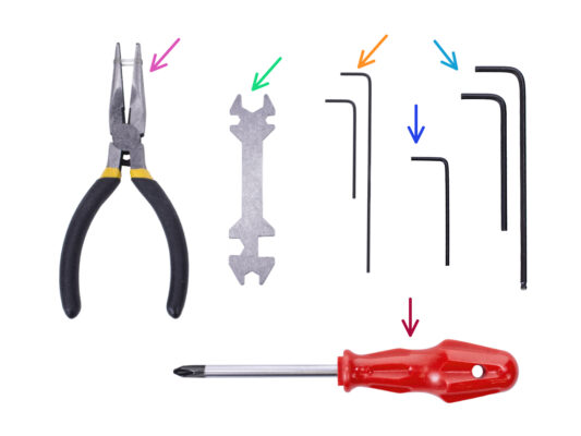

⬢Please prepare tools for this chapter:
⬢Needle-nose pliers
⬢1.5mm Allen key for nut alignment
⬢2.5mm Allen key for M3 screws
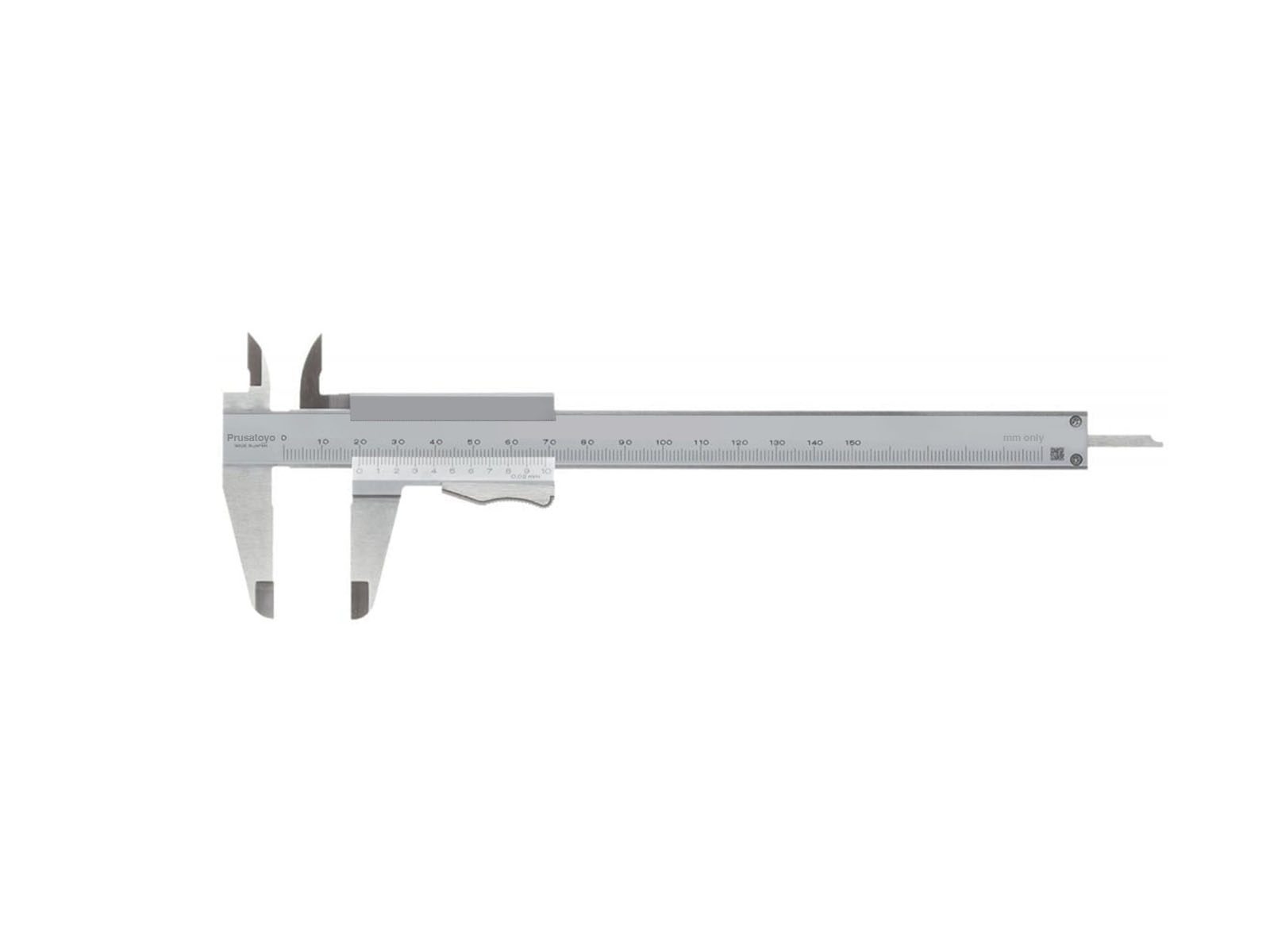
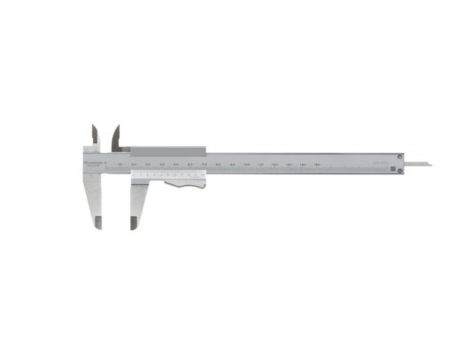
⬢A measurement tool (optional), a digital caliper would work the best.

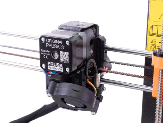

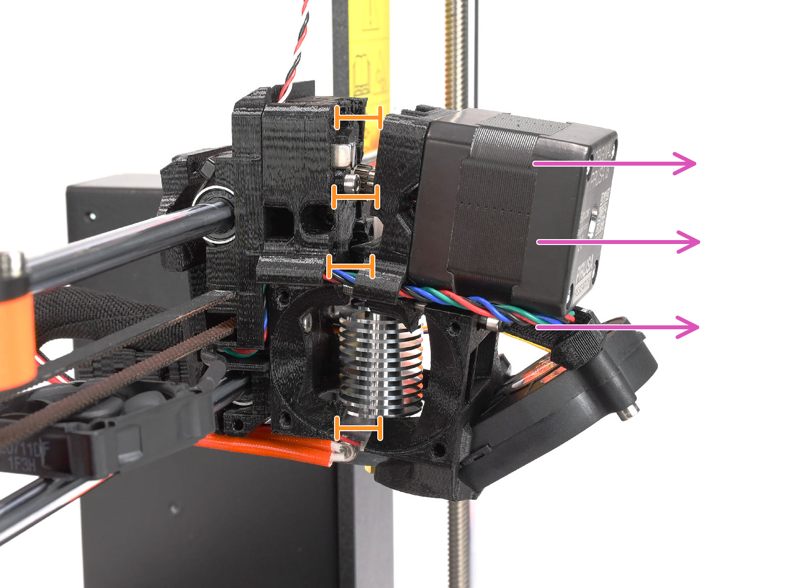
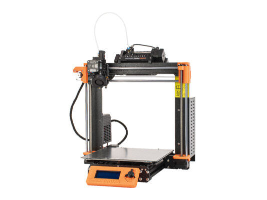
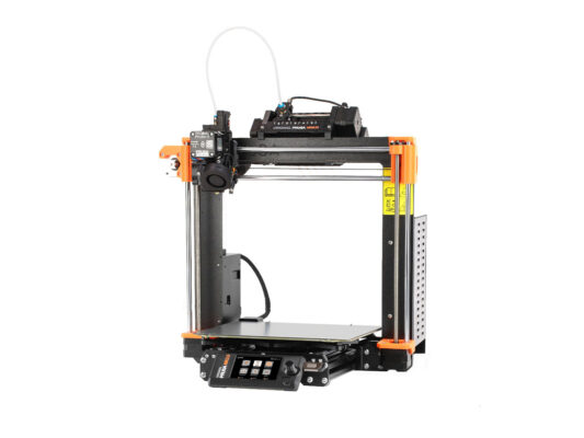
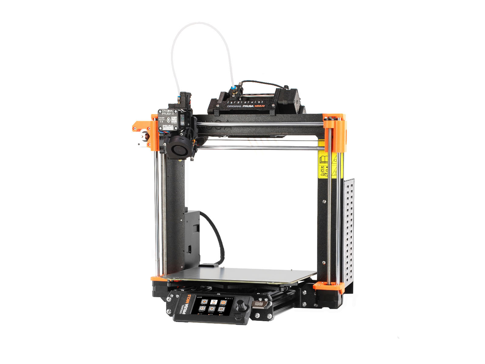
This chapter will describe a modification of the single-material MK3S+ / MK3.5 extruder to accomodate MMU3.

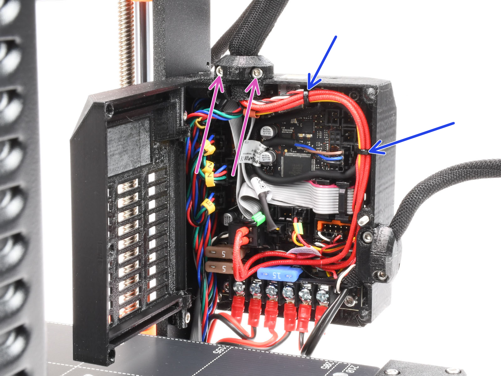

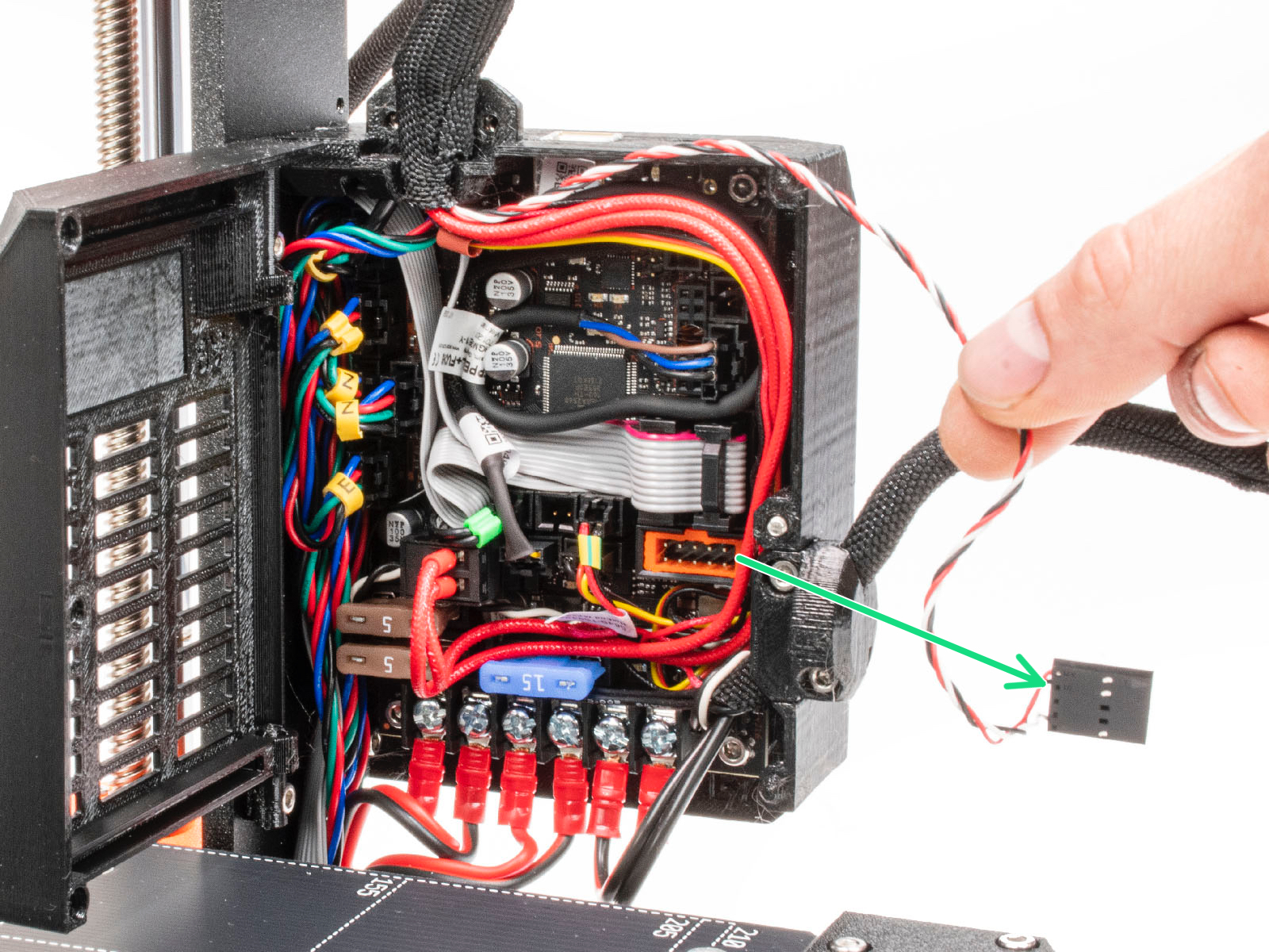

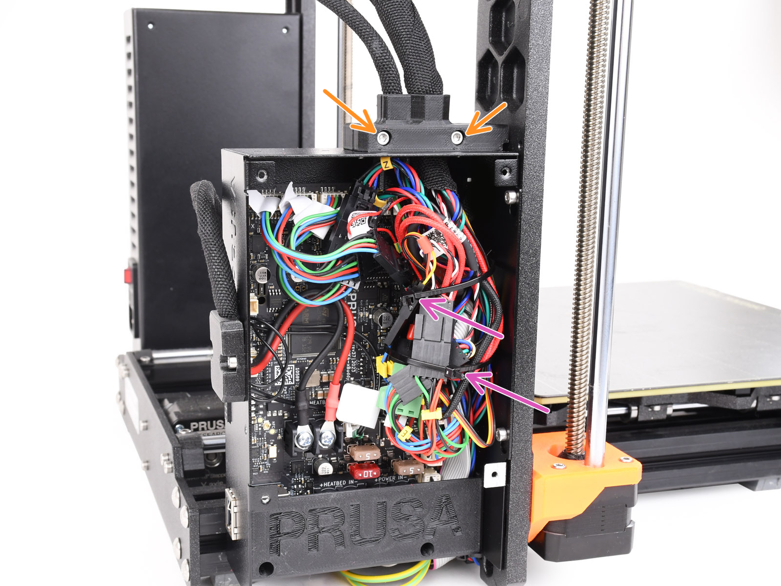
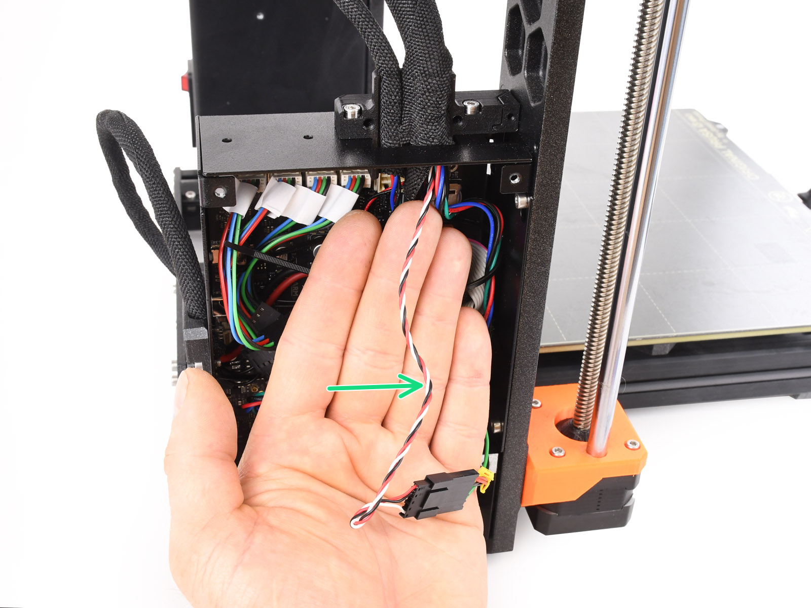

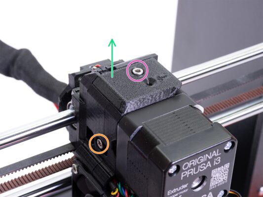
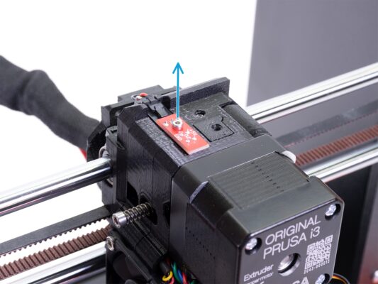

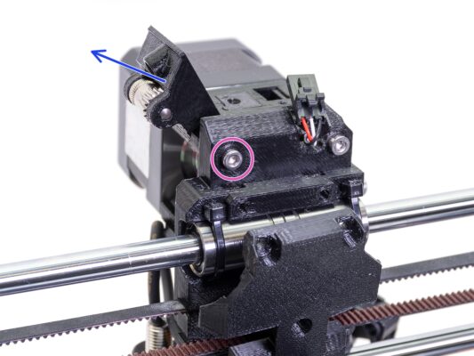

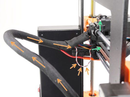
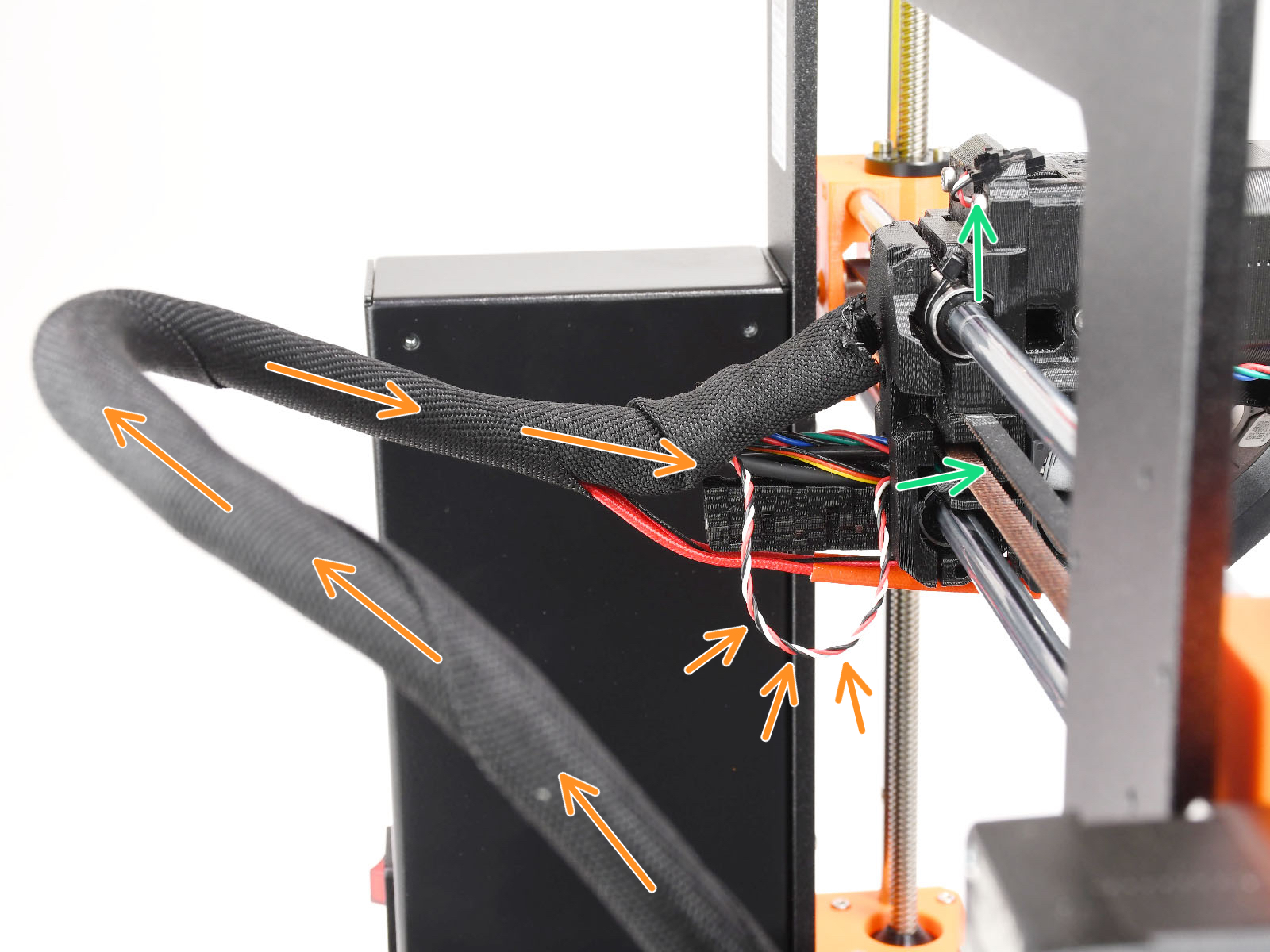
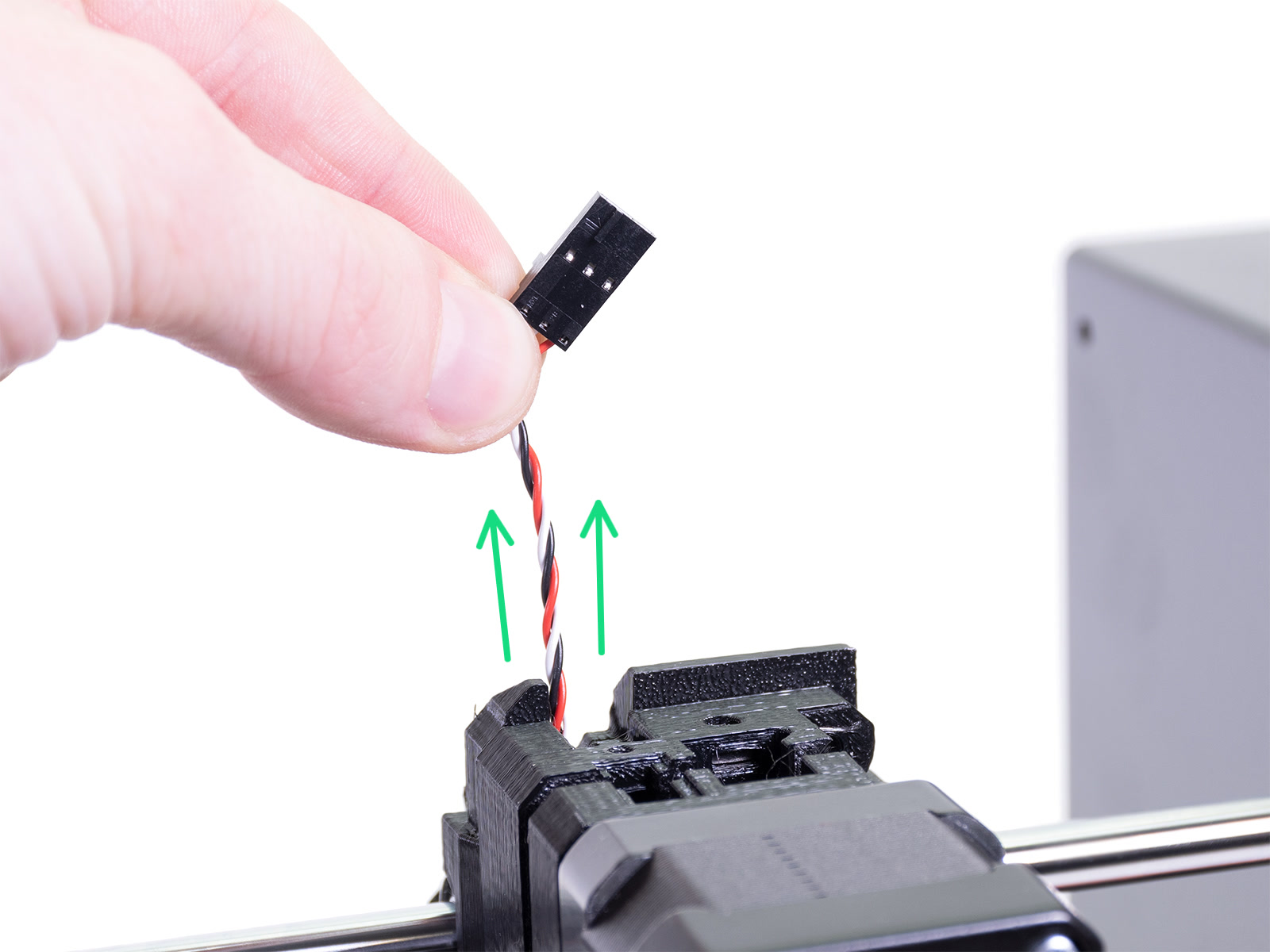

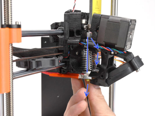
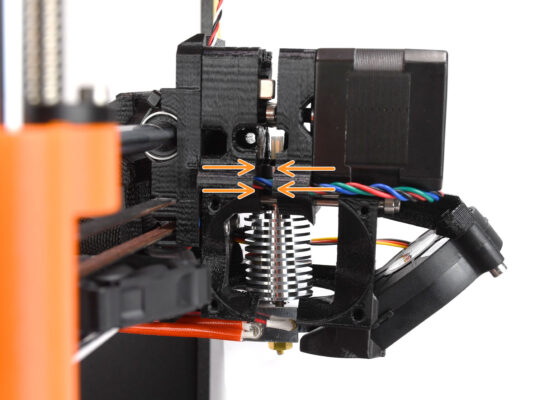
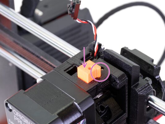
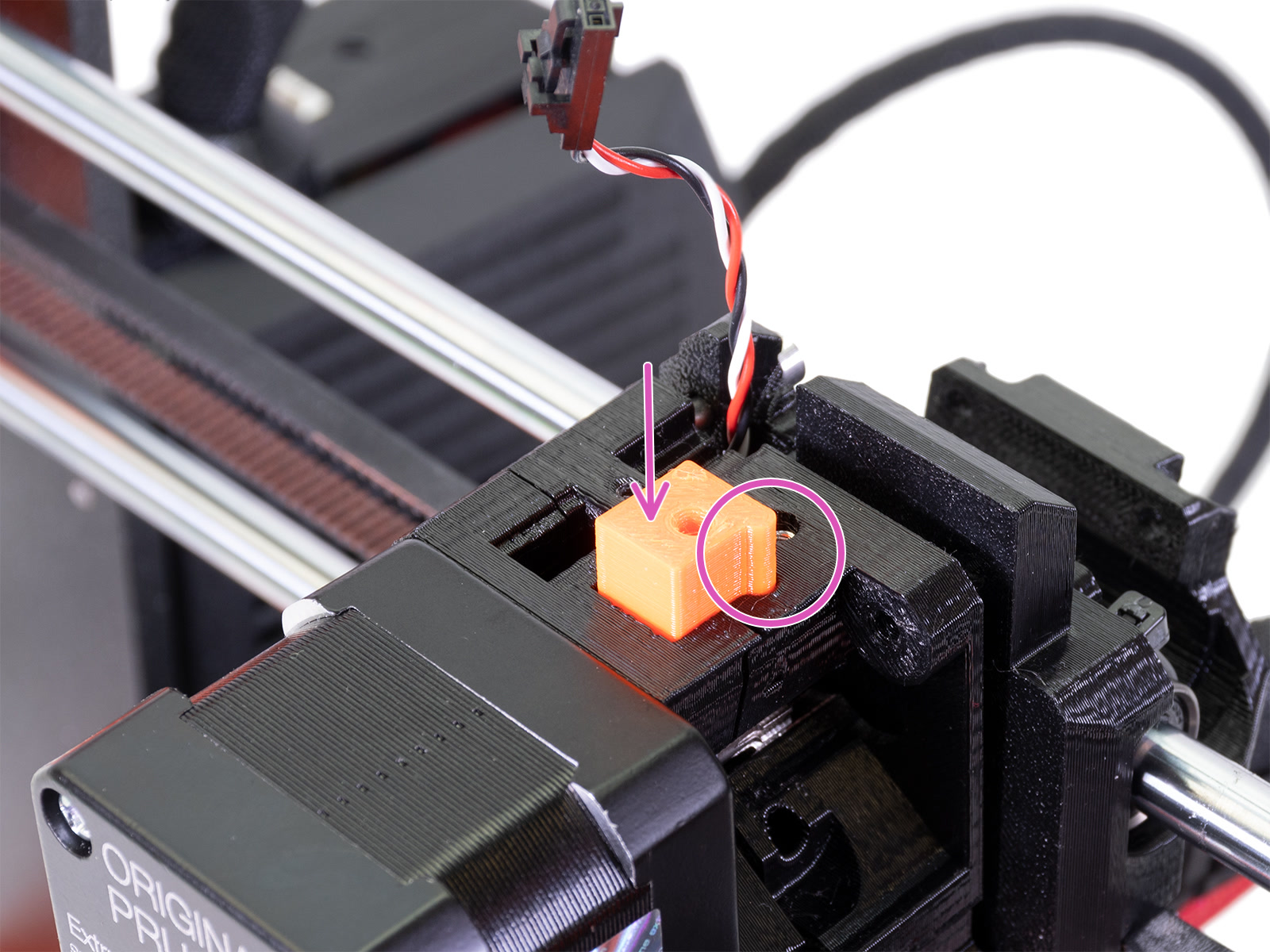
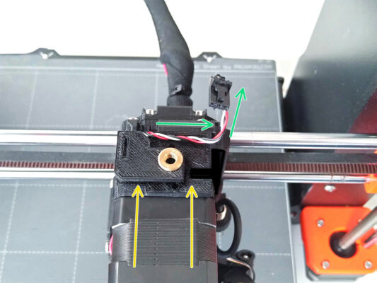
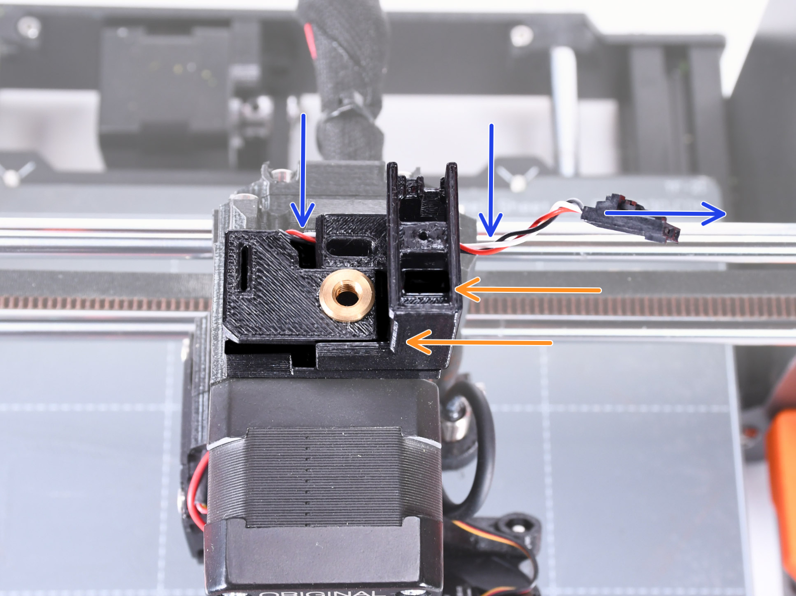
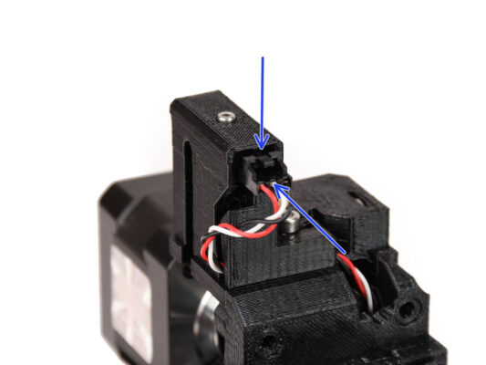
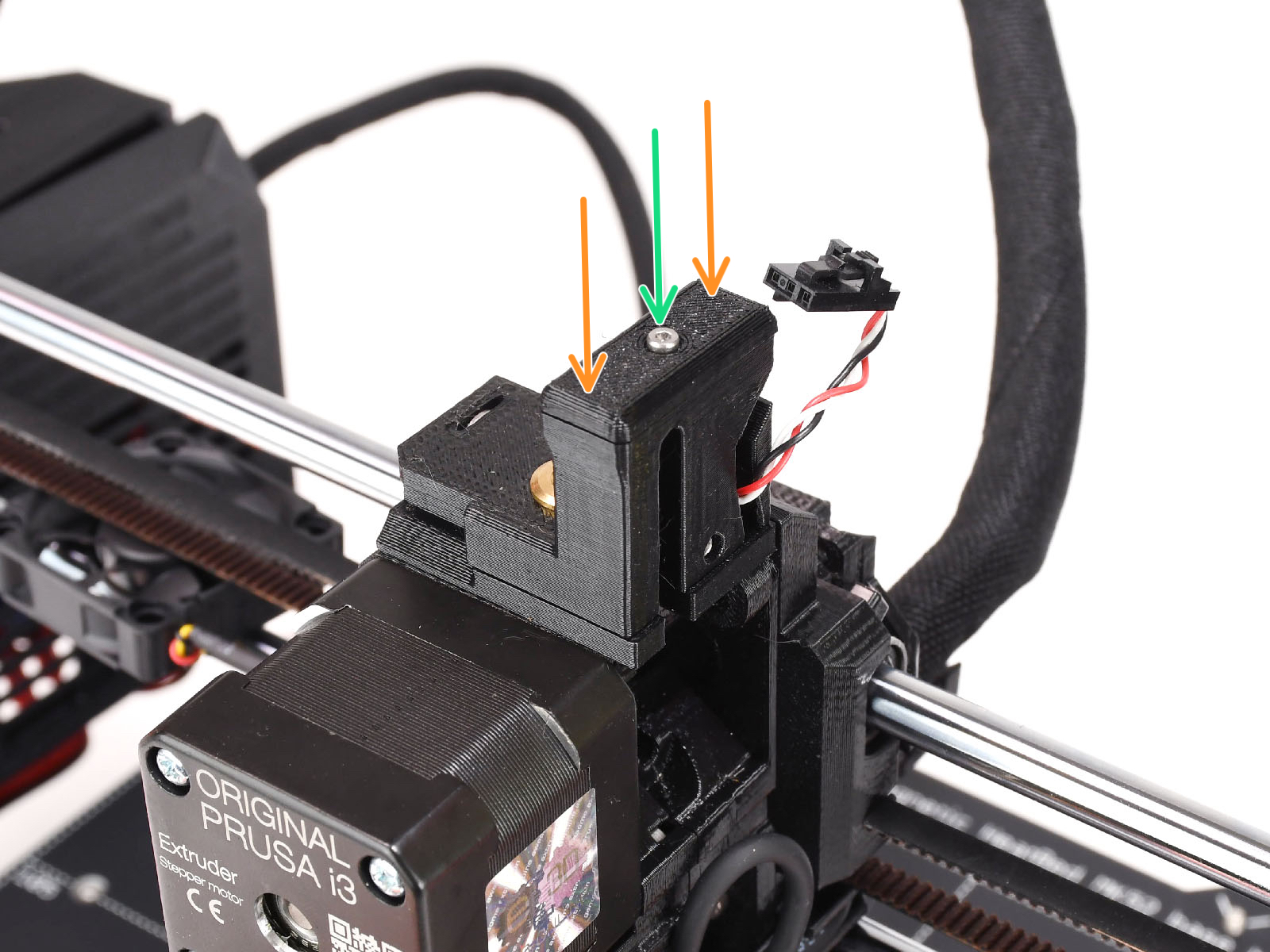
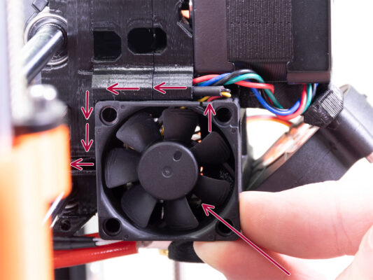
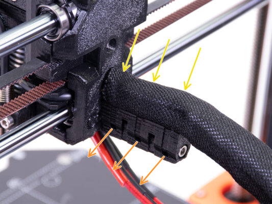
Push the cable towards the extruder from the electronics box, while you are pulling the cable on top. This way, the cable should slide without a significant resistance.
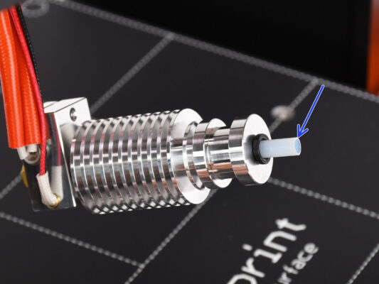
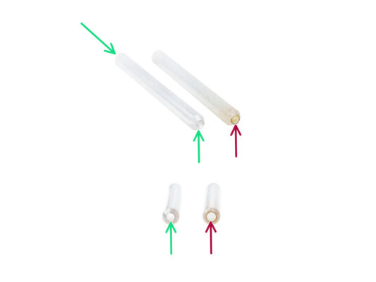

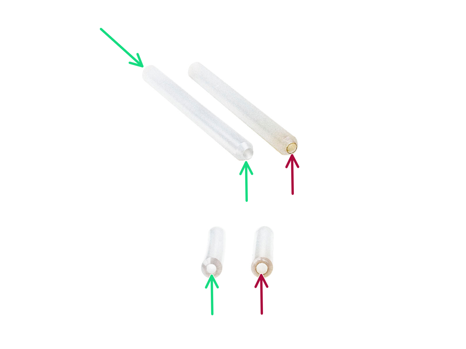
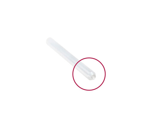
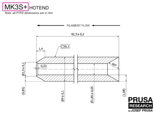
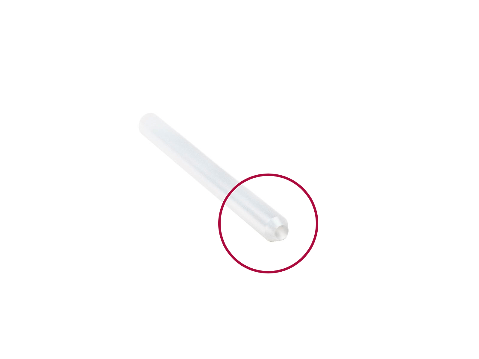
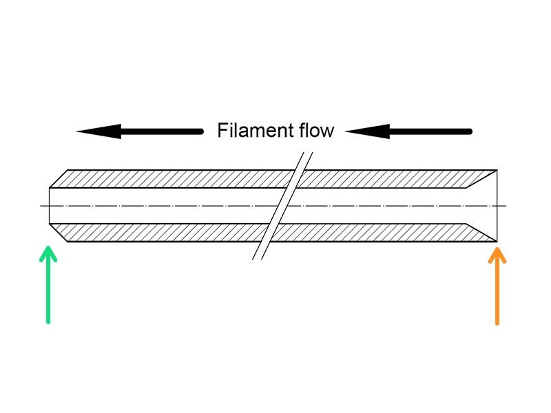
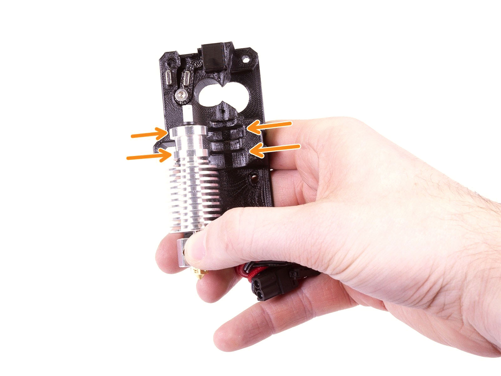
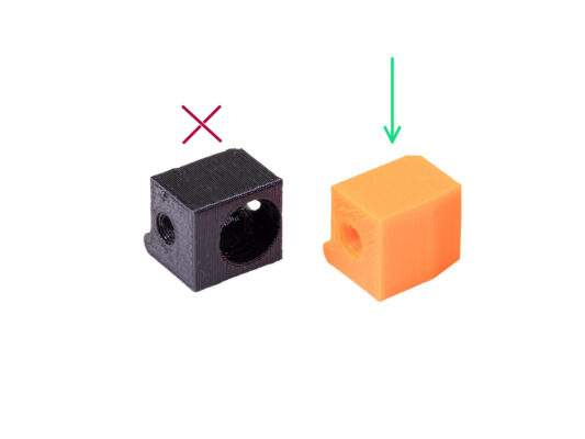
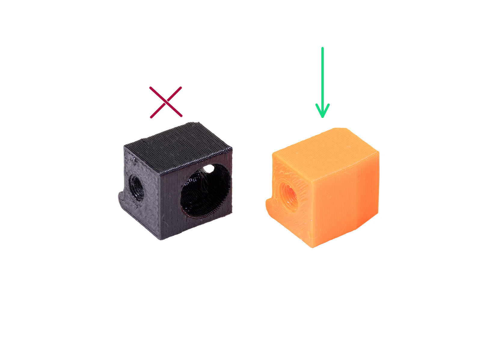
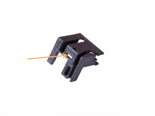
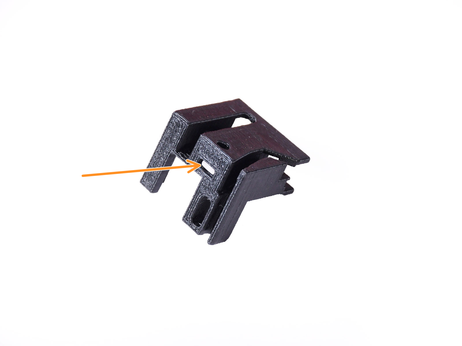
A new hotend PTFE tube has a 1.85mm internal diameter. If your printer is new or very lightly used, you can skip the PTFE replacement in the upcoming steps and proceed to "Adapter-printer parts preparation."
The specimen on the right, however, was taken off a printer after approx. 20000 material changes, using a high-temperature abrasive filament that wore down the tube’s bore up to 2.4mm. This caused increased stringing and malformed filament tips, leading to frequent MMU filament loading problems on that machine. The worn PTFE tube needed replacement.


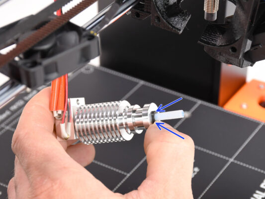
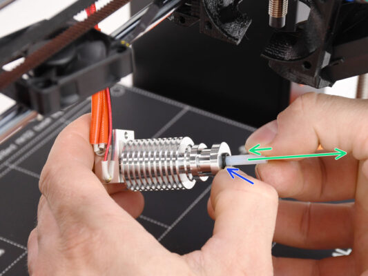


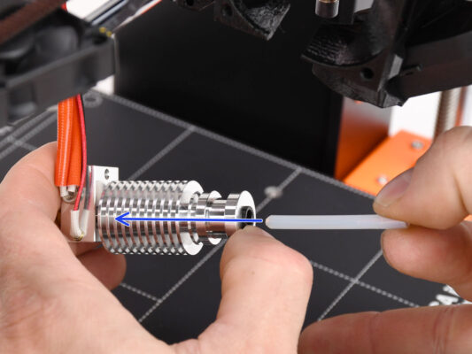
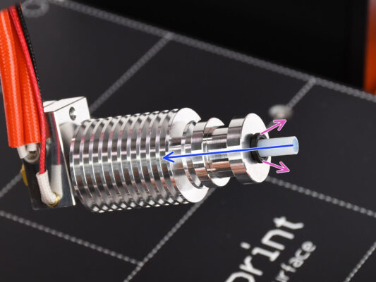
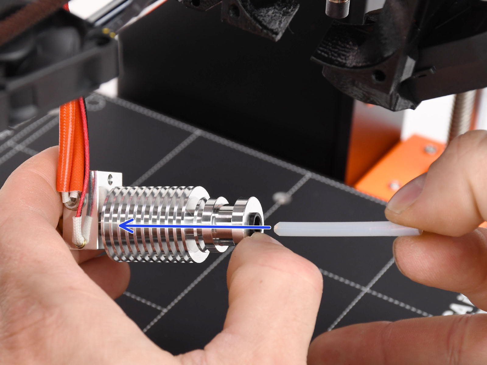

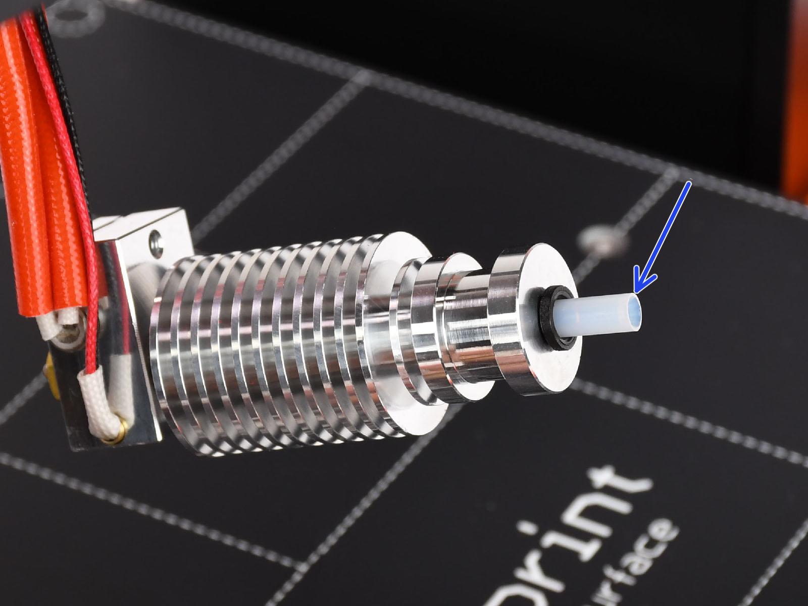
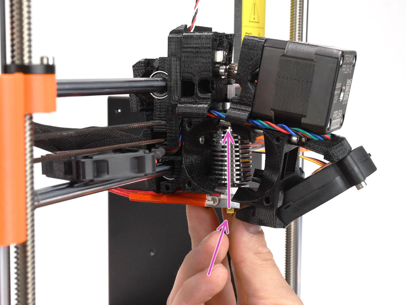
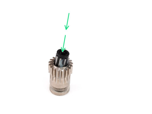
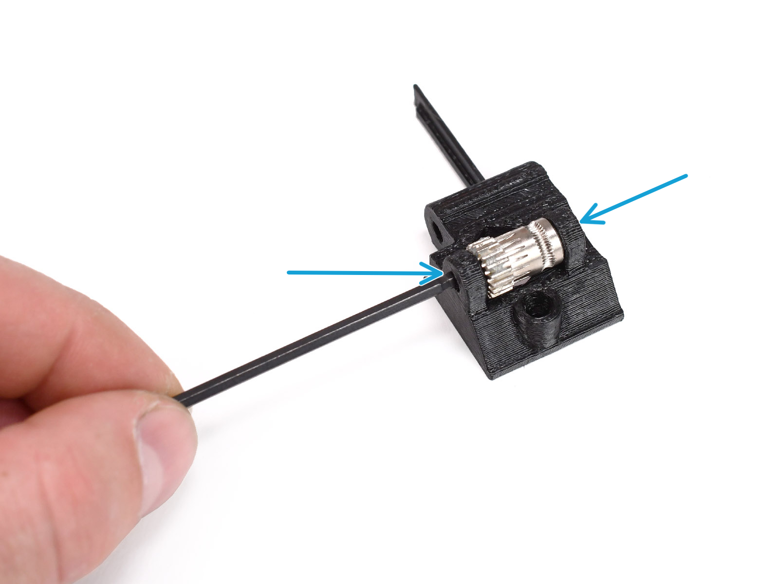
Using your other hand pull the collet out while you keep pushing the PTFE tube in. THIS IS CRUCIAL for the hotend to work properly.


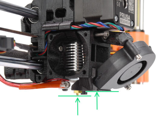
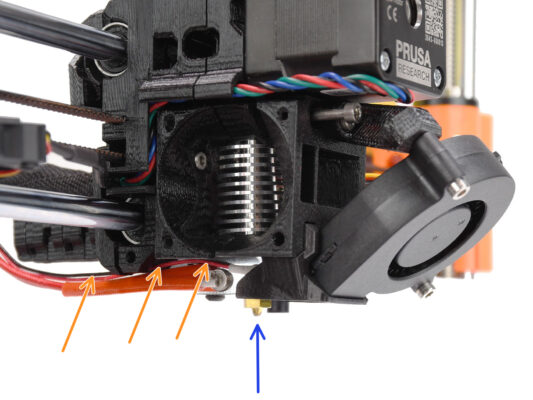

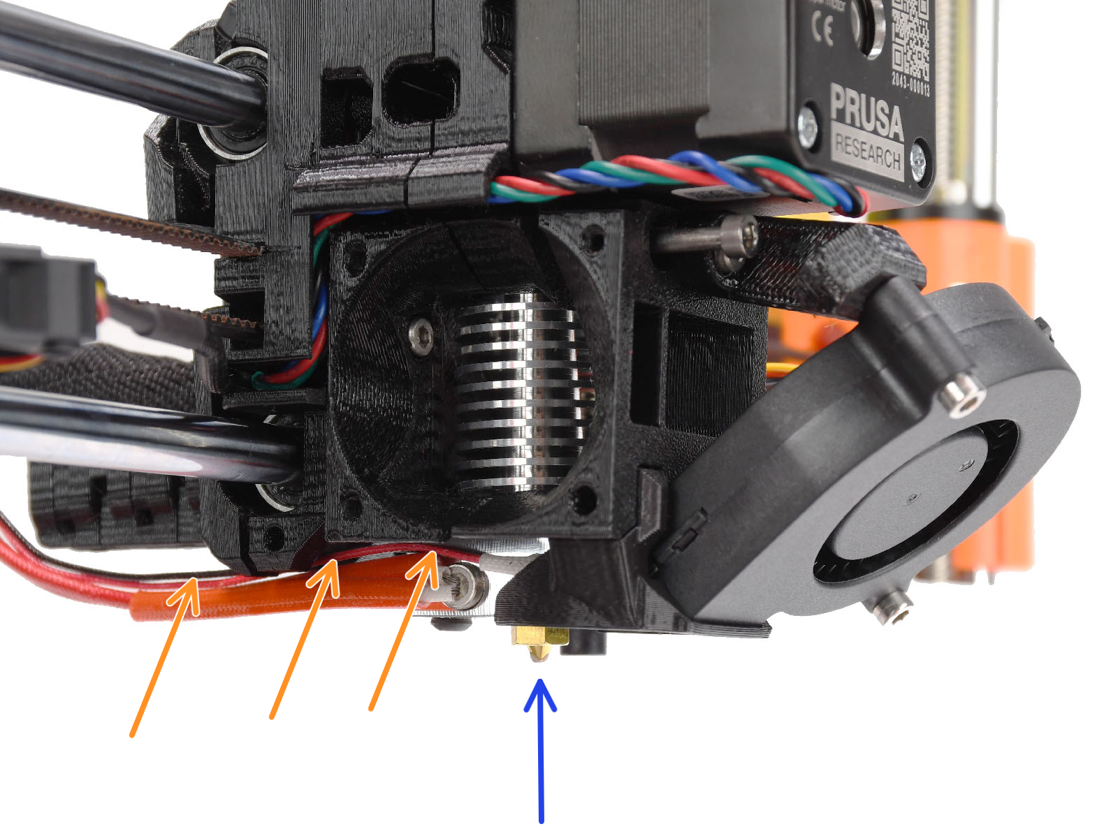
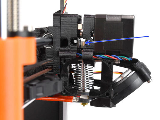
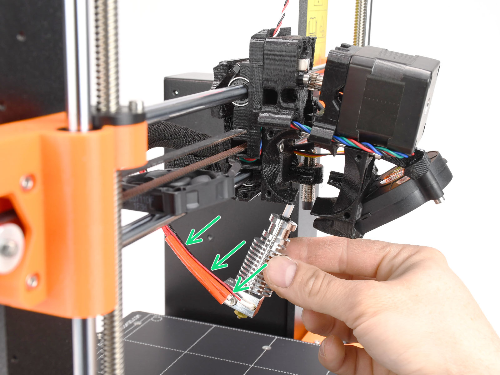
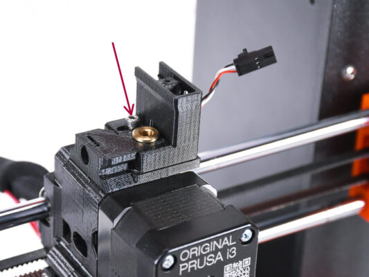
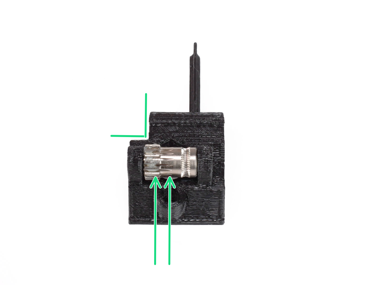
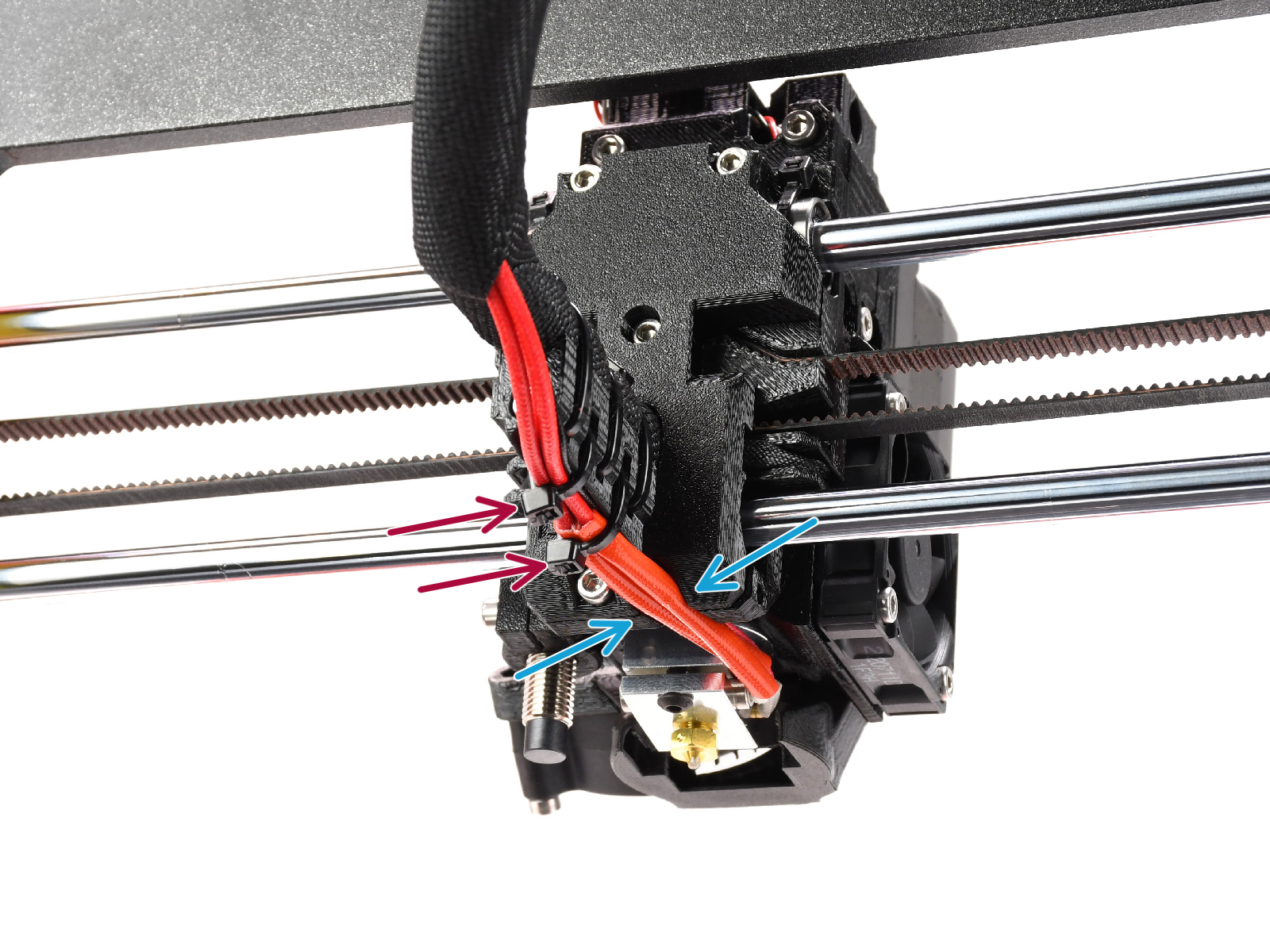
Take a look from the side of the extruder. The nozzle should be slightly below the printed fan-shroud.
If it is significantly lower than in the picture, your hotend isn’t inserted correctly.


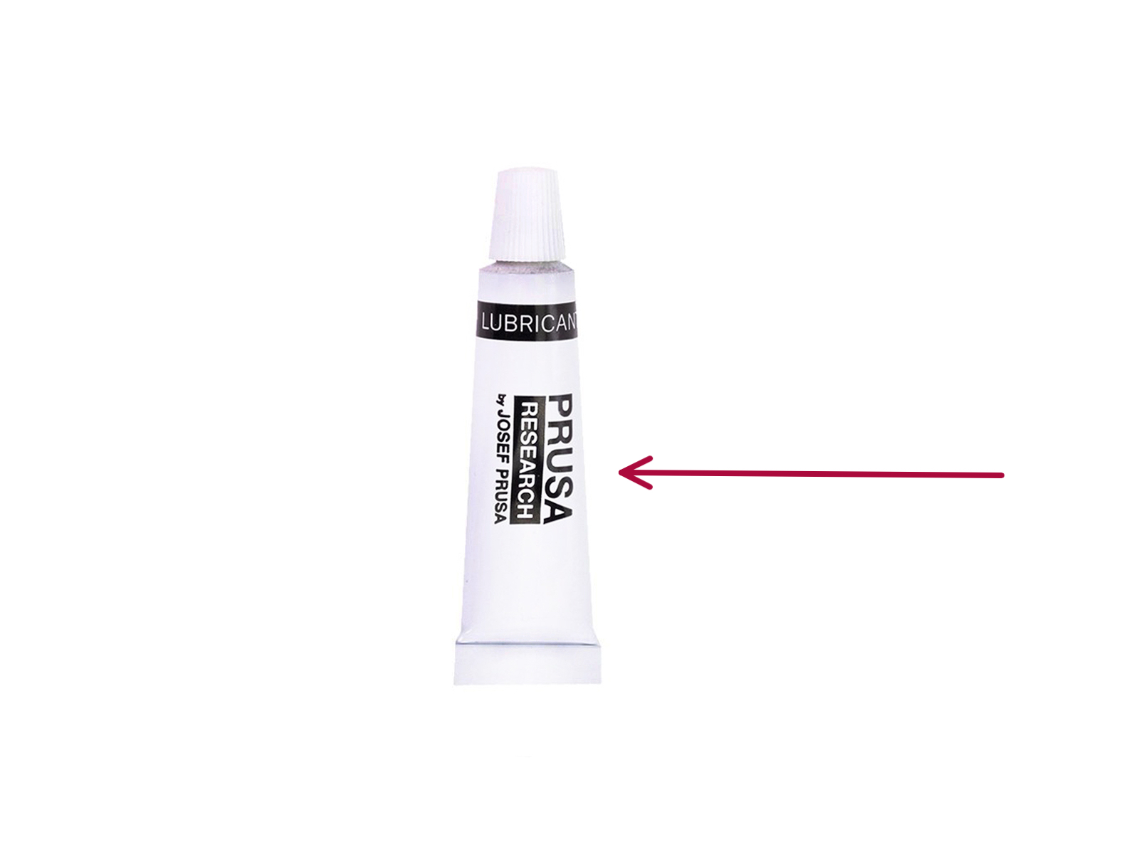
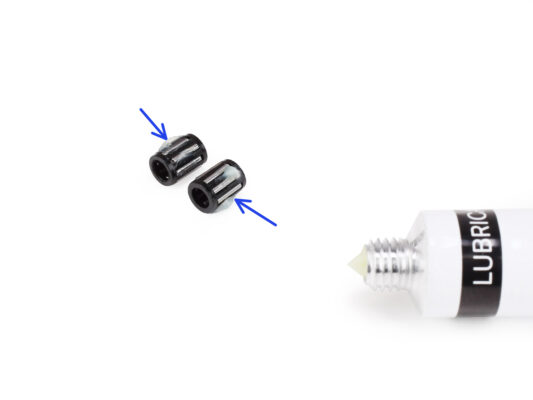


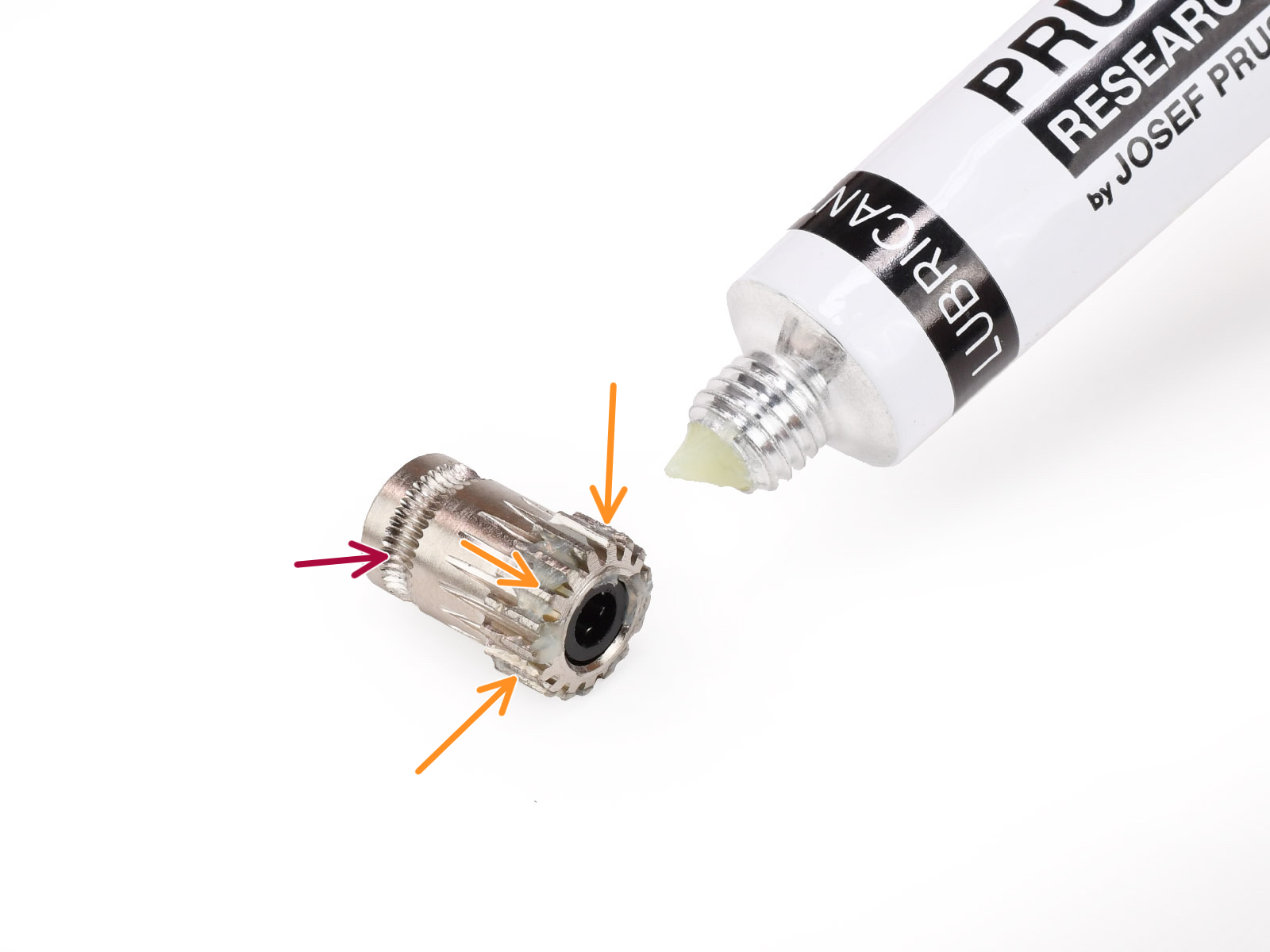
Make sure the lubricant doesn’t get into the filament groove.


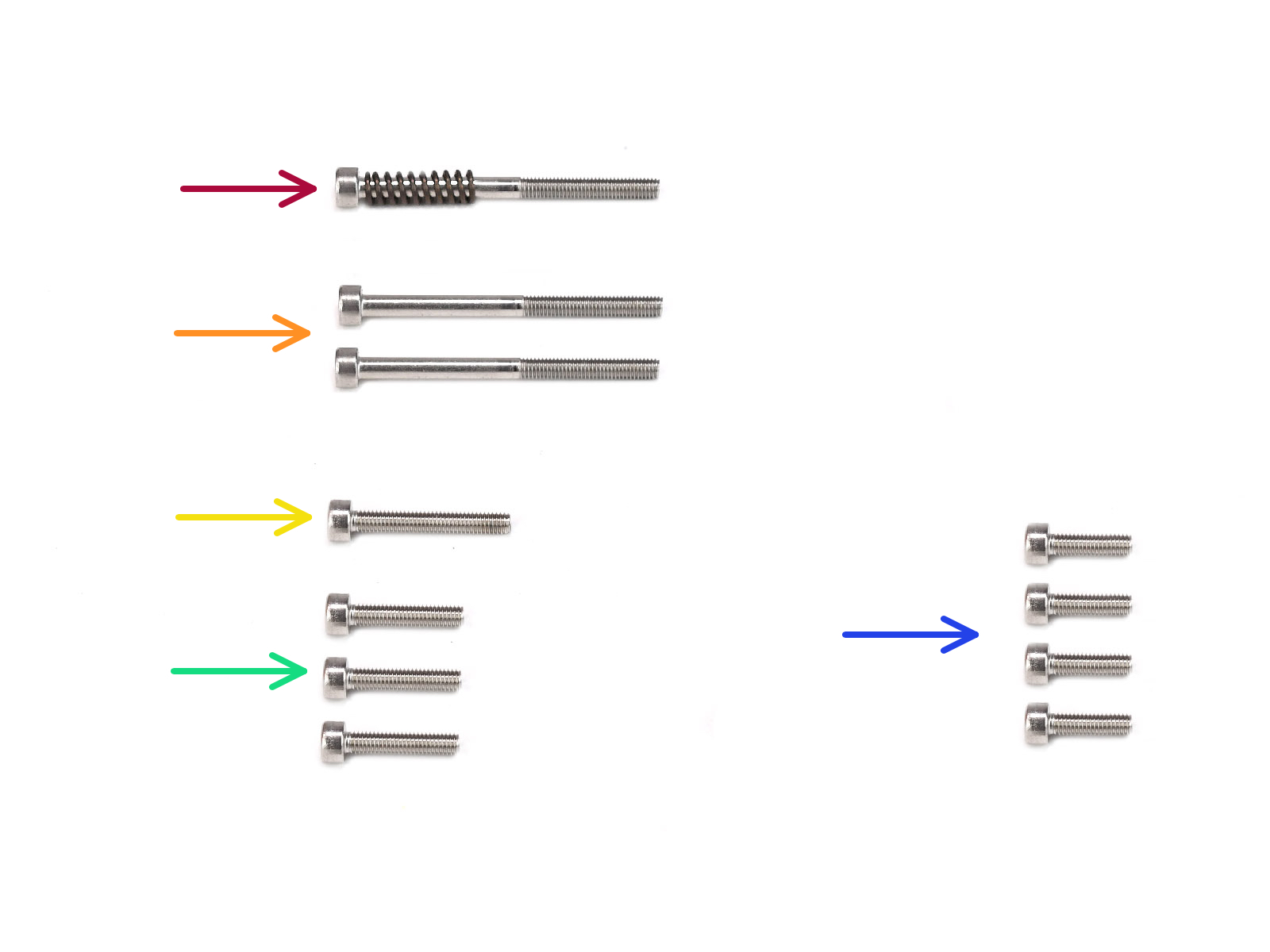
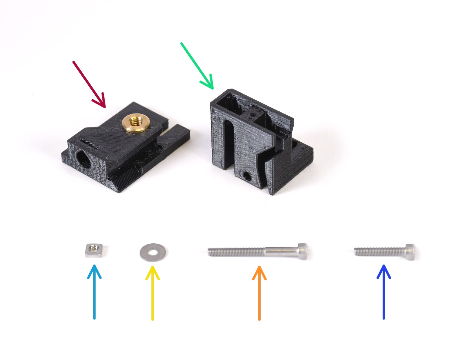
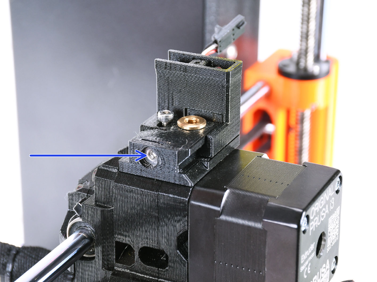
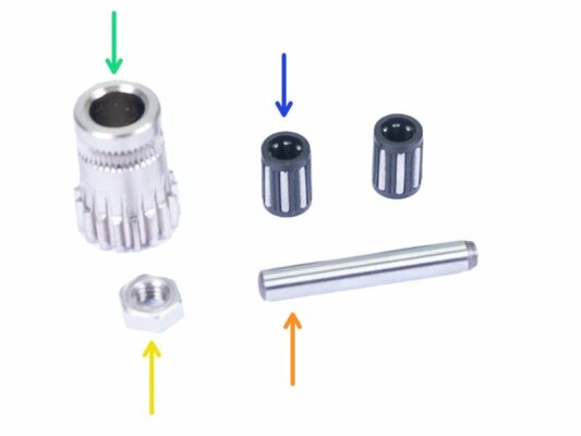
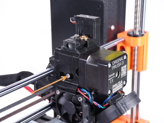
M3x40 screw with spring (1x) (Extruder Idler tension screw. Might be still in the extruder.)
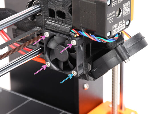

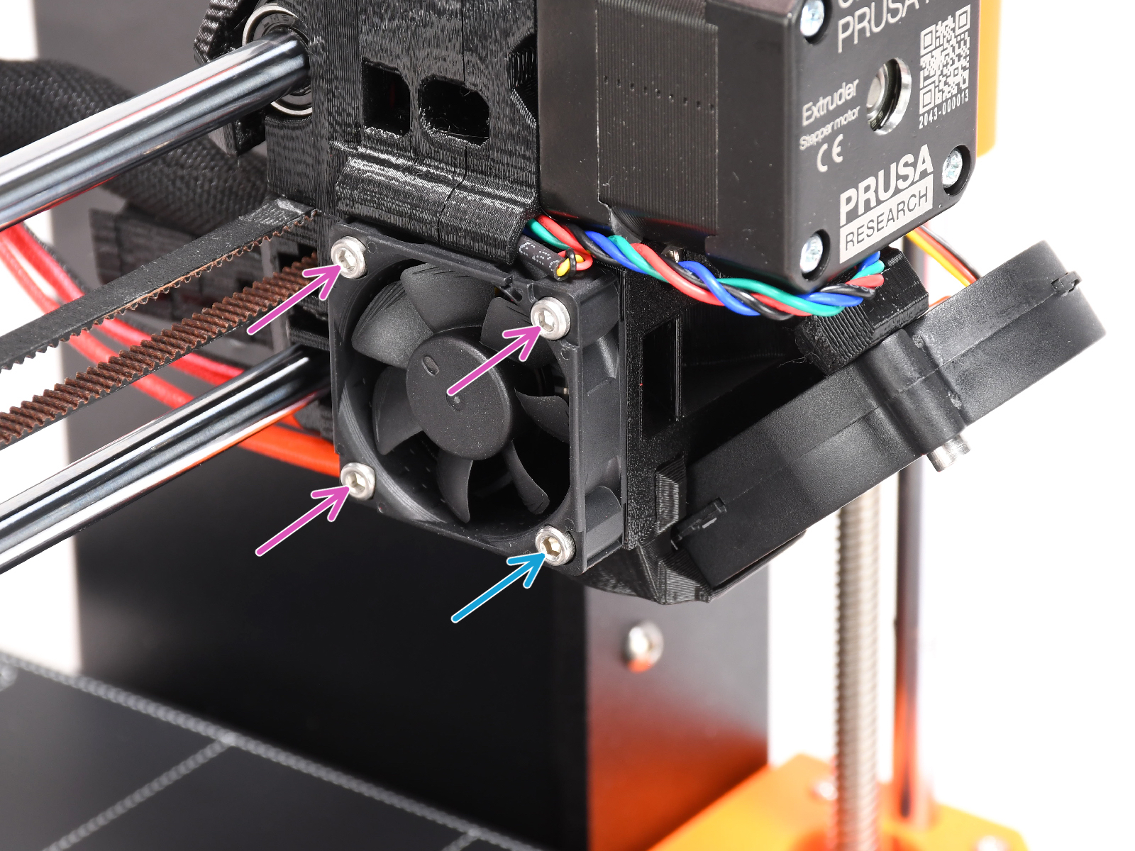

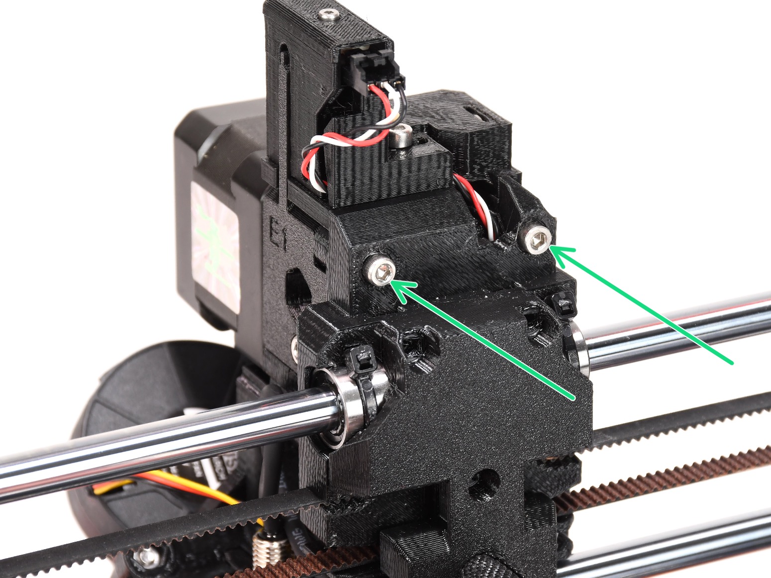


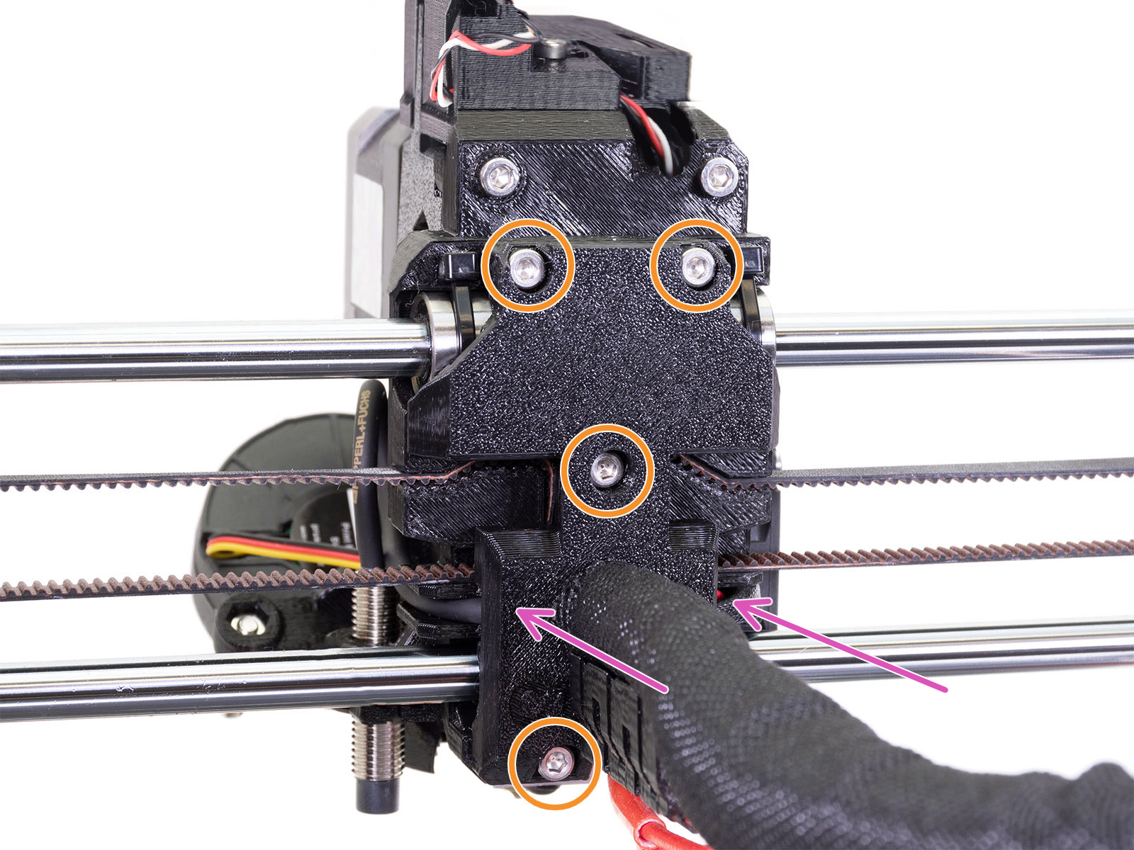
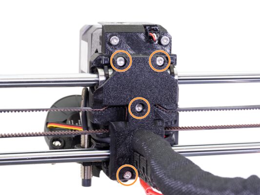
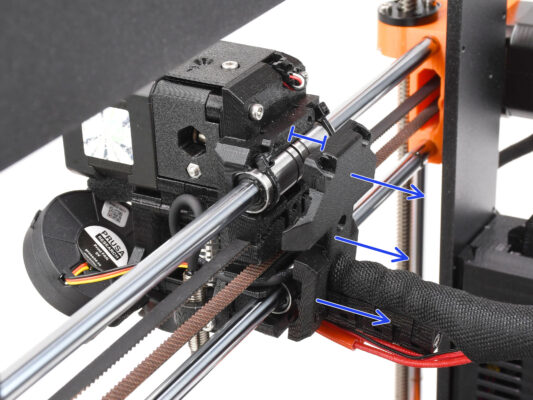
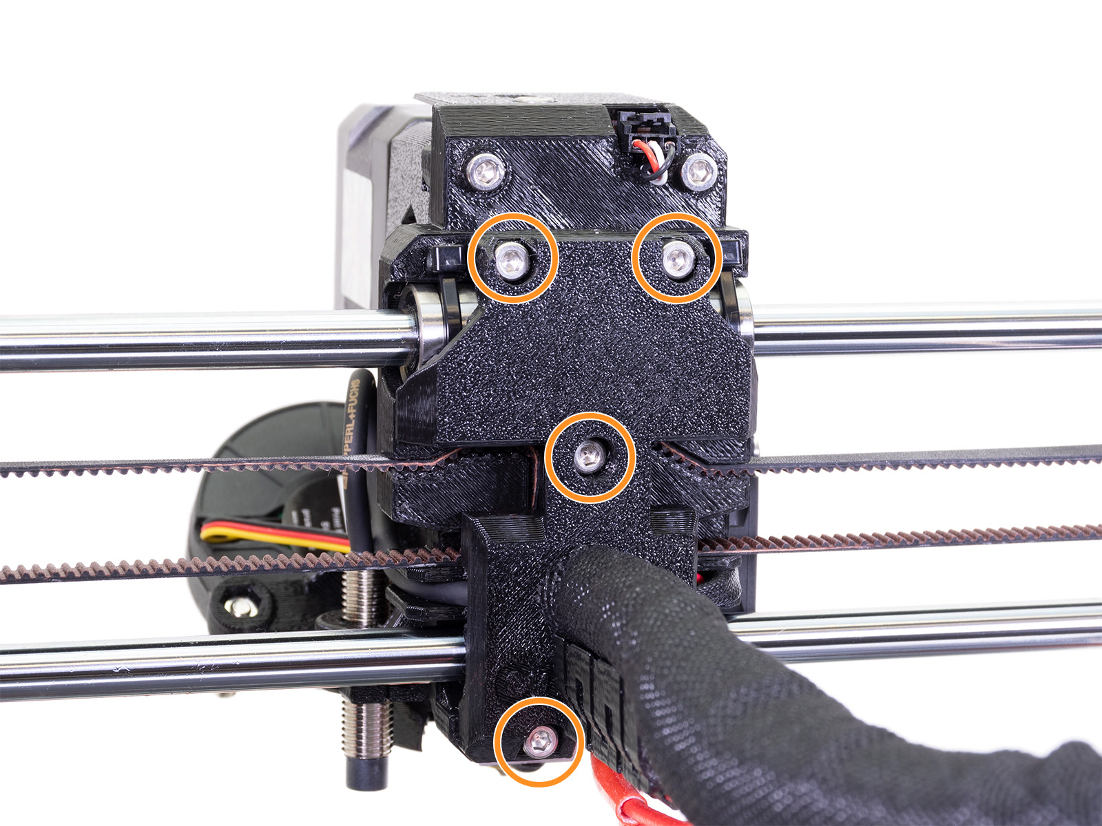
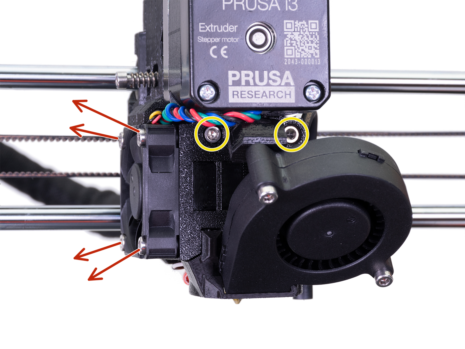
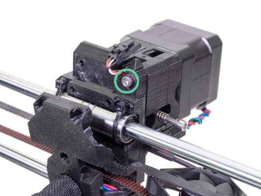
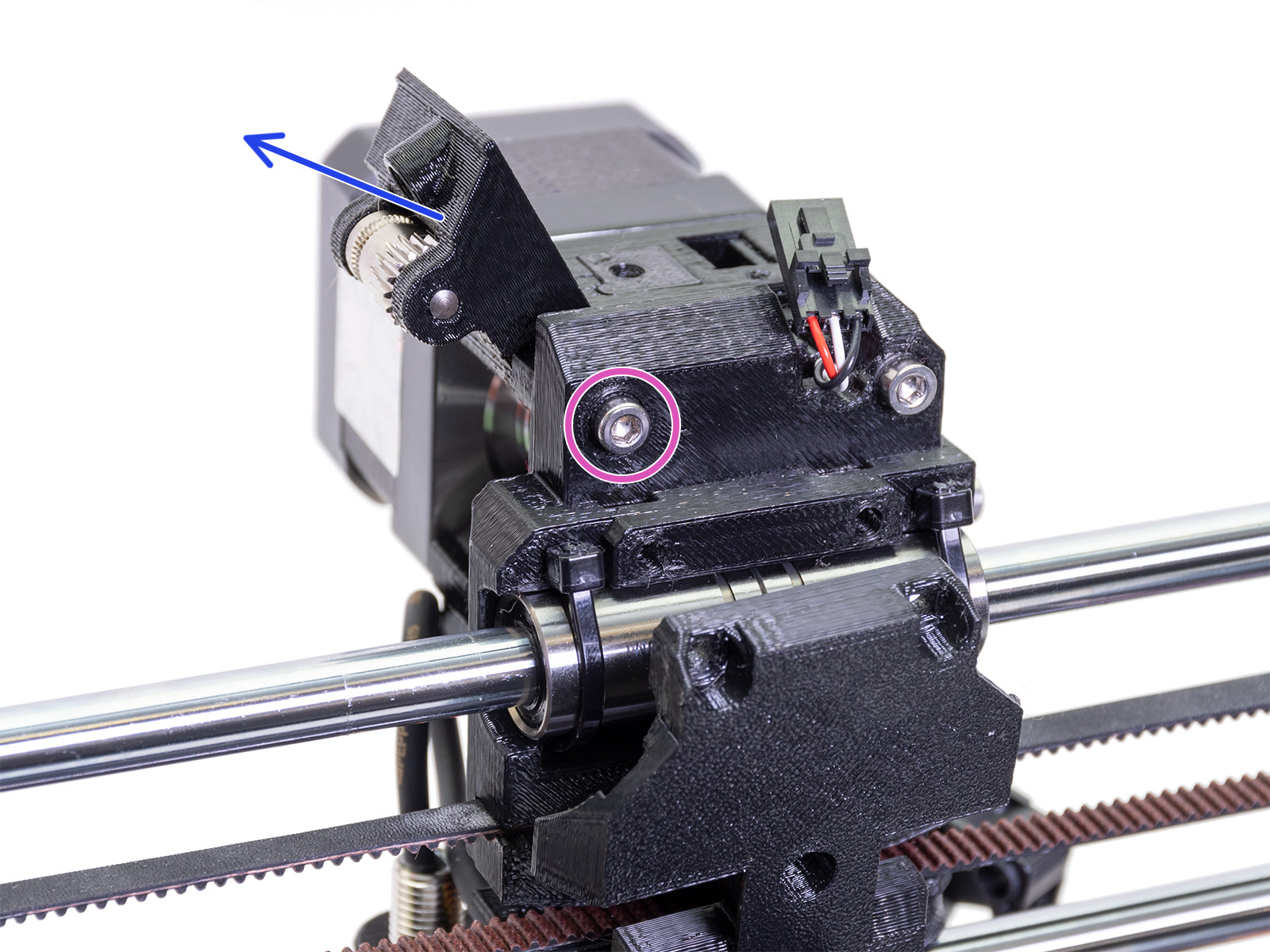
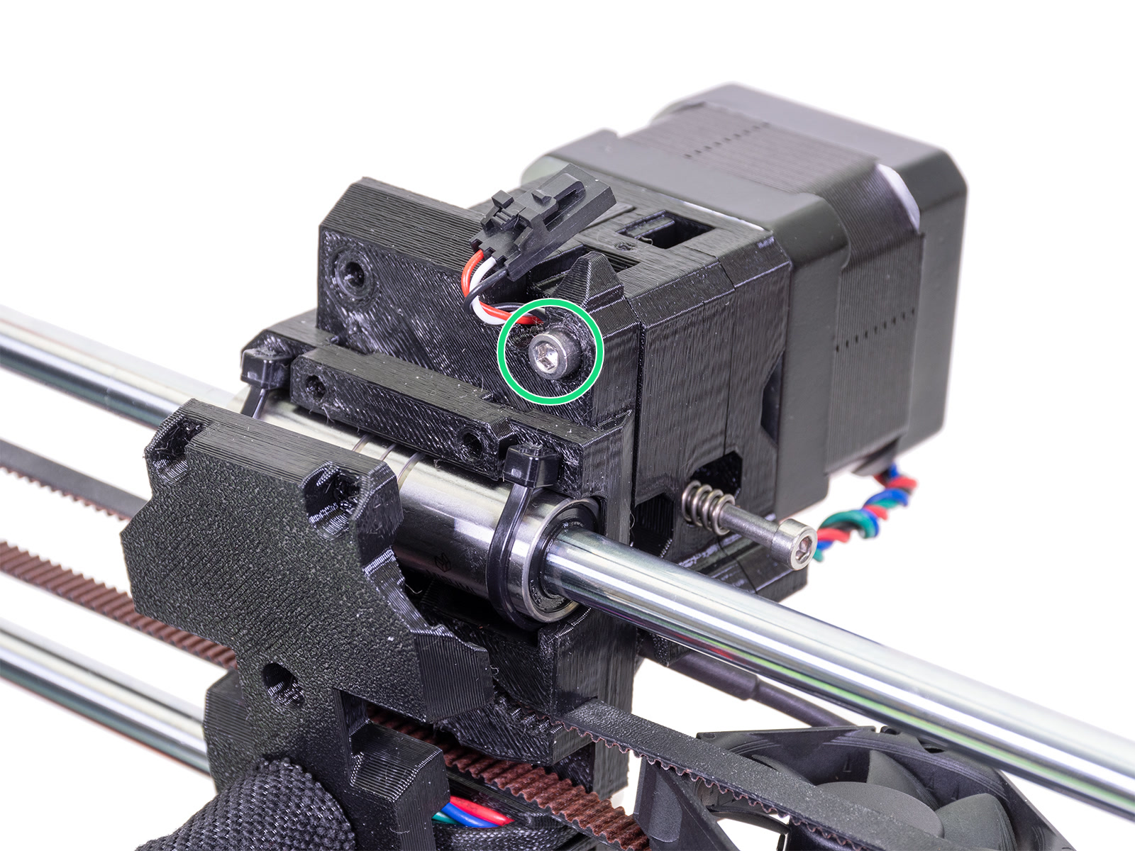
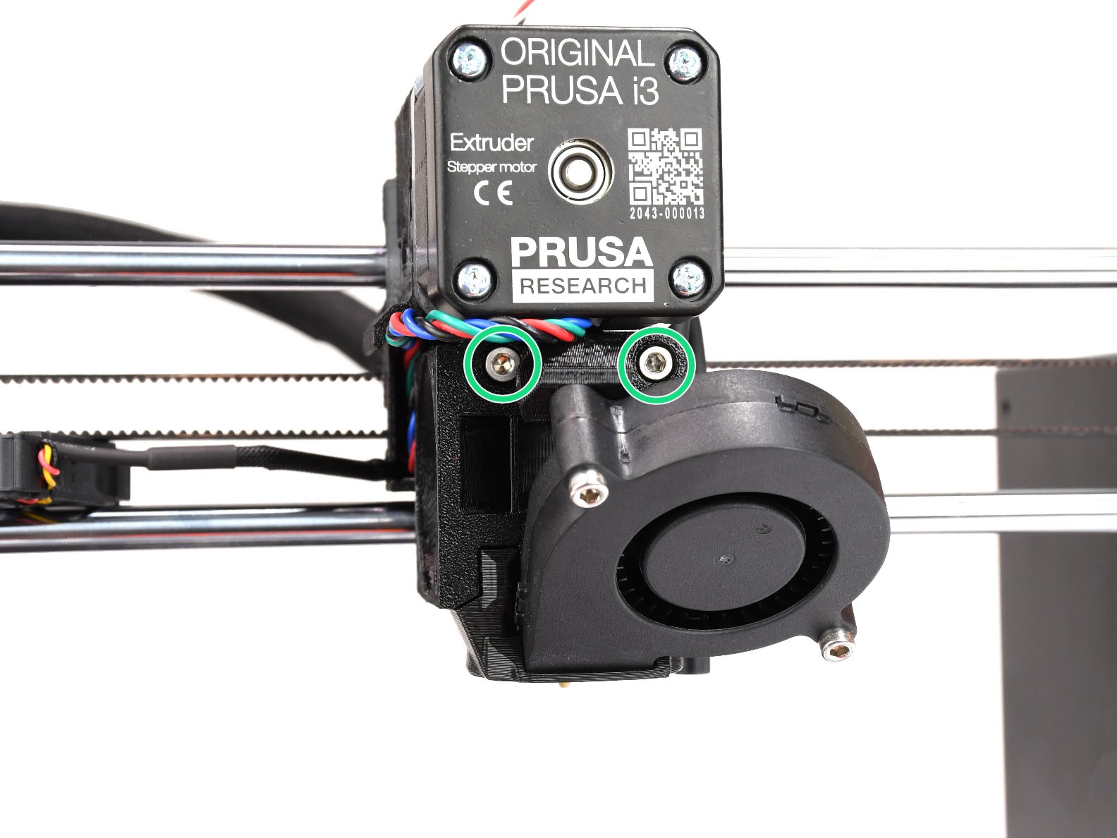
Tighten the screws with a reasonable force.
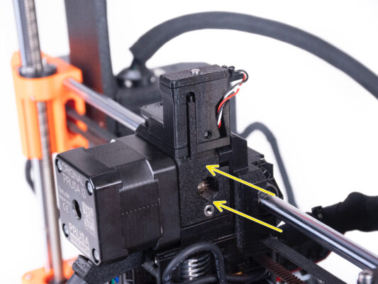
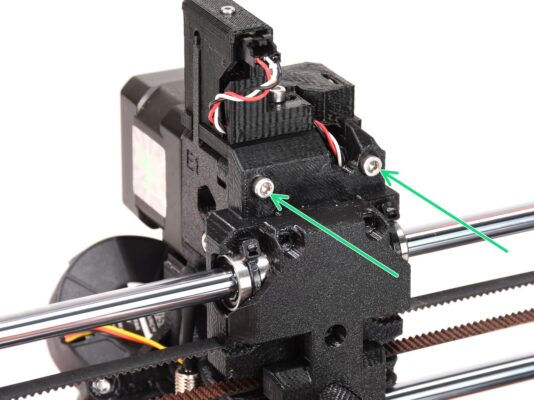
In case the top two screws are tightened up excessively, the top two bearings will resemble a V-shape, the axis won’t be able to move correctly and the top X-axis rod will get damaged. Tighten the top screws just lightly. Remember, the top two bearings are secured by the zip-ties - so the top two screws do not have to be overly tight.


If you have a question about something that isn't covered here, check out our additional resources.
And if that doesn't do the trick, you can send an inquiry to [email protected] or through the button below.

