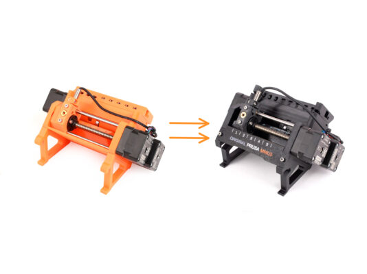
EN
  • Čeština
  • Español
  • Italiano
  • Deutsch
  • Polski
  • Français
Login

2. MMU2S Disassembly (UPG)

2. MMU2S Disassembly (UPG)

2. MMU2S Disassembly (UPG)
Relevant for:
Last updated a month ago
2. MMU2S Disassembly (UPG)
 Difficulty
Easy
 Steps
18
 Available languages
CSPLDEESITFR
Introduction
Introduction
Introduction
Introduction
In this chapter, we will partly disassemble the MMU2S unit and harvest a few key parts to be used for the MMU3 build.
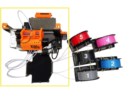
Ensure your MMU printer is powered off and disconnected. Unload all filaments from both the printer and the MMU unit.
If there is a filament loaded in the extruder, use the Unload filament function in the menu.

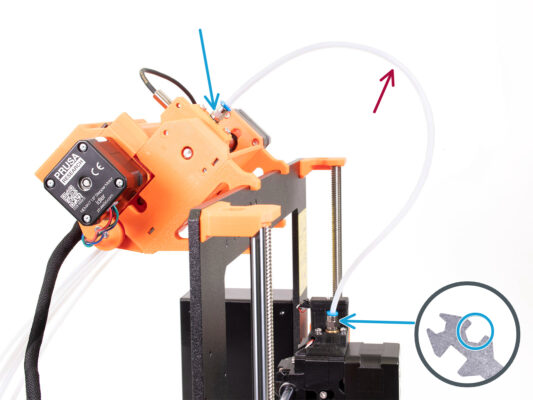
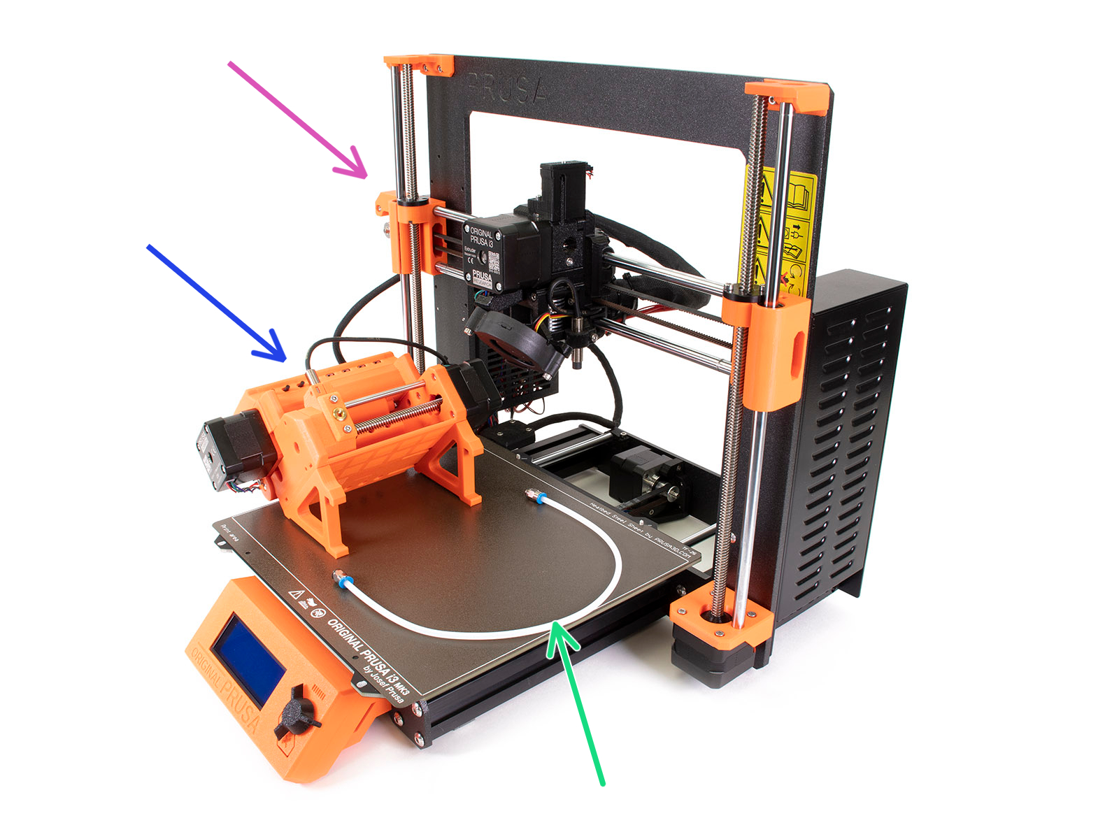
In the upcoming steps, we'll start by detaching the MMU unit from the printer and disconnecting the buffer from it.

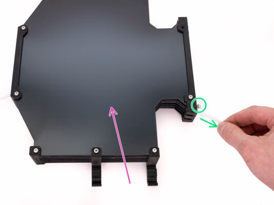
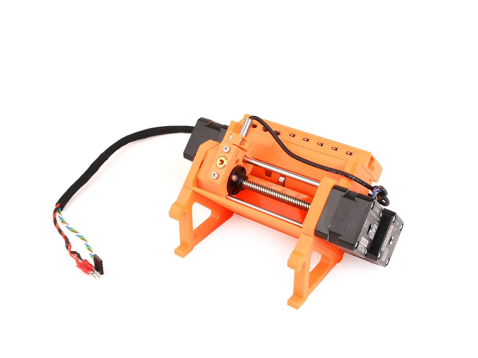
Pay close attention to the description. When instructed, put aside the components from the MMU2S. Specific parts will be used again in a later step.
Maintain a well-organized workspace to avoid mixing older parts with the new ones. Although some new components might resemble the old ones, they are actually distinct. Note that certain components shouldn't be reused for MMU3, while others are necessary for the upgrade.
Tools necessary for this chapter
Please prepare tools for this chapter:
Needle-nose pliers
Unikey to loosen the Festo fittings
2.5mm Allen key(s) for M3 screws
Phillips screwdriver for power cable terminals
You can use your own tools if you find them more suitable.
Disconnecting the PTFE tubes
Unscrew the Festo fittings QSM-M5 from both the printer and the MMU unit. If the fittings are tight, you can use the Unikey or an 8mm wrench.
Keep the PTFE tube with the fittings aside for disassembly later.
We will have to disconnect the buffer from the MMU unit.
Loosen all the screws on the buffer securing the PTFE tubes connected to the MMU unit. Remove all five tubes by pulling them out.
Keep the buffer for a later disassembly in the next chapter.
On the back of the MMU unit, slightly loosen the four screws holding the rear-PTFE holder.
Remove all five PTFE tubes and dispose of them immediately. These tubes will not be used again for MMU3.
MMU3 is designed to work with differently-sized PTFE tubes. Reusing MMU2S tubes during the assembly of MMU3 will result in incorrect operation.
Disconnecting the MMU2S (part 1)
Loosen the M3x40 screw on the printer's electronics box.
Open up the electronics box.
From the MMU, you'll see a data cable along with two power cables, all connected to the Einsy control board of the printer.
Never move, connect, or disconnect cables while the printer is powered on. Doing so can cause damage to the electronics.
Begin by disconnecting the MMU data cable.
Be careful not to disconnect the Filament sensor cable located just below the MMU data cable.
Disconnecting the MMU2S (part 2)
With a Philips screwdriver, gently loosen the two power terminals located on the bottom left side of the Einsy board.
The MMU power cable fork connectors are stacked over the main power supply connectors for the Einsy. Remove only the MMU's fork connectors individually, leaving the main supply connectors in place.
Using the Philips screwdriver, thoroughly secure the power terminals with the MMU disconnected. Confirm that all connections match the picture.
Take out the MMU cable bundle from the electronics box. Close the box and secure it using the M3x40 screw for now.
Removing MMU2S from the printer
The MMU2S unit has been successfully disconnected.
Raise the rear of the unit to detach the holders from the printer's frame. Then, remove the MMU from the printer.
You can set the printer aside for now.
We can move onto disassembling the MMU2S unit itself.
For the following step, please prepare the MMU-to-Extruder PTFE tube with the Festo fittings QSM-M5 attached.
MMU-to-Extruder PTFE tube disassembly
Take the MMU-to-Extruder PTFE tube with the Festo fittings QSM-M5.
Remove both Festo fittings on the old PTFE tube.
Hold the Festo fitting by the metal part and press the blue collet in. While the collet is pressed, first press the PTFE tube in, then pull it out entirely.
MK3S+/ MK3.5 owners: Save the Festo fittings for later use. Discard the PTFE tube so you don't confuse it with a new one later on!
MK4/MK3.9 owners: Throw the Festo fittings and the PTFE tube away now! Your package includes new Festo and PTFE tube. Mixing them may lead to issues!
MMU3 is designed to work with differently-sized PTFE tubes. Reusing MMU2S tubes during the assembly of MMU3 will result in incorrect operation.
MMU2S Unit disassembly
Remove the two M3x18 screws holding the electronics on top of the unit.
Remove the two M3x30 idler tension screws with the springs.
Remove the electronics board assembly from the unit.
Disconnect all cables from the electronics board. Remember that each connector has a safety latch that needs to be pushed in order to remove a plug. Set aside the board assembly.
Gently cut the zip ties that are securing the cables together.
Be extremely careful not to damage the cables!
Textile wrap removal
Separate the power and data cable bundle from the rest of the cables.
Remove the textile wrap off the cables and save the textile wrap for later use.
The MMU2S power and data cables won’t be used in MMU3.
Idler motor removal
Idler motor removal
Idler motor removal
Idler motor removal
Using the ball-end Allen key at an angle, remove the two M3x10 screws from the top holding the Idler motor.
Open the idler body and remove the two M3x10 screws that secure the motor from the opposite side.
Remove the two M3x10 screws holding the motor shaft to the idler barrel.
Pull out the idler motor from the unit. Save it for future use.
5x16sh shafts removal
Remove the four M3x18 screws holding the Rear-PTFE holder.  Remove the holder as well as all the PTFE tubes underneath.
Remove the M3x10 screw on the side securing the 5x16sh shaft.
Using the shorter side of the 2.5mm Allen key, push the 5x16sh shaft from the inside out.
Repeat the same process on the other side. Remove the M3x10 screw and push the 5x16sh shaft outward.
Save the 5x16sh shafts for later use.
Bearings removal
Bearings removal
Bearings removal
Bearings removal
Remove the Idler body with the Idler.
These components are no longer needed. However, they contain valuable spare parts inside. Disassembling them can be challenging, so we won't do it at this point.
Using the Allen key, tilt the 625ZZ bearing on the right side of the Pulley body in order to remove it.
Using the same technique, remove the bearing on the other side too.
Save both the 625ZZ bearings for later use.
Selector motor removal
By rotating the selector motor shaft, move the selector all the way to the left side.
Using the 2.5mm Allen key, remove the five M3x10 screws holding the motors.
Rotate the motor shaft some more to disengage it from the selector.
Pull out the selector motor to remove it from the unit.
Save the motor for later use.
Selector removal
Selector removal
Selector removal
Selector removal
There are two openings on the side of the unit. You can see the selector shaft ends through them.
Insert the Allen key into the openings to push both the shafts all the way in.
Pull out both the 5x120sh shafts and save them for later use.
If you opt to use the needle-nose pliers to pull the shafts out, pull them out while doing a twisting motion. Be careful not to scratch them!
Lift the selector up and remove it from the unit. Set it aside for now, as we will be further disassembling it.
There is a sharp blade on the back of the selector. Proceed carefully to avoid an injury!
Pulley motor removal
Turn the unit around.
On the bottom side, remove the remaining M3x10 screws holding the pulley motor.
Remove the pulley motor from the unit.
Save the motor for later use.
Using the Allen key, tilt the pulley bearing in order to remove it. Save it for later use too.
Selector disassembly
Remove the two M3x10 screws holding the trapezoid nut.
Remove the trapezoid nut and save it for later use.
Remove the M3x10 screw on the side of the selector.
Remove the FINDA / SuperFINDA sensor and save it for later use.

A steel ball will fall out of the selector.

The ball isn't magnetic and won't be re-used. We will use a magnetic one later on. Set it aside not to confuse it with the new one.
You don't need the other parts in the selector anymore, but you can keep them as spares.
Control board disassembly
Prepare the electronics board assembly.
Carefully remove the three M3x6 screws holding the electronics board.
Gently loosen the electronics board from the assembly, but don't take it out completely yet. Keep the control board within the plastic part to safeguard it from any harm, for now.
Handle the board by its sides to avoid damage. Be careful around the electronics, do not touch the individual components on the board. Remember that the board is sensitive to electrostatic discharge (ESD).
Summary
Summary
Here's a summary of the parts to keep for later use:
Textile sleeve 450x5 (1x)
Stepper motor (3x) Idler, Selector and Pulley motor (with pulleys still attached)

Electronics: the control board (1x) and FINDA/SuperFINDA sensor (1x)

625 bearing (3x)
Trapezoid nut (1x)
Festo fittings QSM-M5 (2x)
5x16sh shaft (2x)
5x120sh shaft (2x)
Was this guide helpful?

Comments

Still have questions?

Still have questions?

If you have a question about something that isn't covered here, check out our additional resources.
And if that doesn't do the trick, you can send an inquiry to [email protected] or through the button below.

Contact us