- English
- Čeština
- Italiano
- Deutsch
- Polski
- Français
- Home
- キャリブレーション
- 基本的なキャリブレーション
- Multi-tool manual calibration (XL)
Multi-tool manual calibration (XL)
- 基本的なキャリブレーション
- Zキャリブレーションの失敗 (MK3S/MK2.5S)
- 1層目のキャリブレーション (i3)
- 1層目のキャリブレーション(MINI/MINI+)
- Original Prusa i3のすべてのシステムのリフレッシュ
- ギアボックスの位置合わせ(MK4)
- アイドラーネジ張力の調整
- Live adjust Z (Z微調整)
- メッシュベッドレベリング
- MMU2S Setup and Inspection
- MMU3 Setup and inspection
- Multi-tool manual calibration (XL)
- Procedure
- Selftest (SL1)
- セルフテストの失敗 (MINI/MINI+)
- Selftest failed (MK2/S, MK2.5, MK2.5S)
- Selftest failed (MK3.5)
- セルフテストの失敗 (MK3/MK3S/MK3S+)
- セルフテストの失敗 (MK4)
- Temperature Calibration
- XYZ Calibration (MK2.5/MK2.5S)
- XYZ Calibration (MK2/S)
- XYZ キャリブレーション(MK3/MK3S/MK3S+)
- XYZキャリブレーションの詳細
- 高度なキャリブレーション
- キャリブレーションエラーメッセージ
The multi-tool manual calibration for the multi-tool versions of the Original Prusa XL can be done to ensure that the Tool Offset Calibration worked correctly and to fine-tune the offset for each tool. This calibration is also recommended after a nozzle crash, or if a custom nozzle is in use. We prepared a specific test GCode for the dual-head and five-head versions, designed to cover offset errors up to +/-1mm.
The print has two zones labeled X and Y, each with one comb for each tool, excluding Tool 1. For each comb, find the two marks in each zone that are most aligned with the comb printed with Tool 1 and read their values.
The largest mark represents 0 and the medium marks represent 0.5mm.
In the following visualization of the 2-Tool calibration GCode, the orange parts are printed with Tool 1, and the magenta parts with Tool 2.
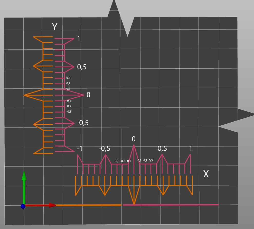 | 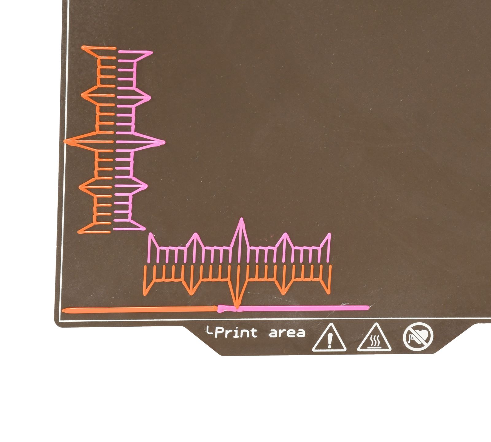 |
The 5-Tool calibration GCode has the same properties, but it has four combs per axis. Each tool offset is compared to Tool 1.
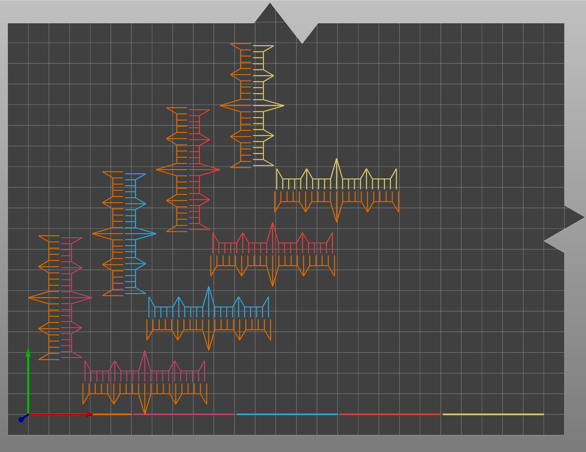 | 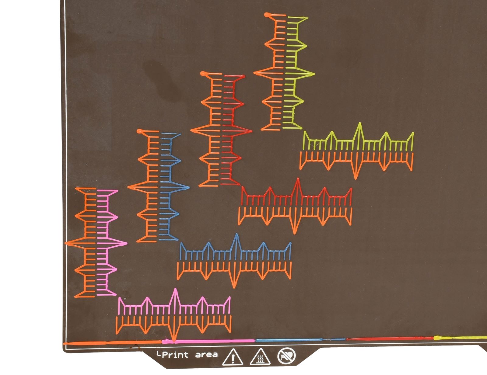 |
Procedure
- Print the model. Use one of the GCodes, to print in PLA, depending on the number of tools.
- After the print is finished, remove the steel sheet with the print still on, and observe the marks. If you are in doubt between two marks, choose their average value (for example, if 0mm and +0,1mm are both almost aligned, then choose an offset of +0,05mm).
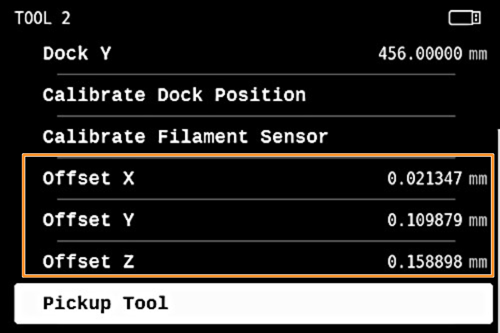
- Adjust the offsets by adding the measured offset to the offset already shown for the selected tool in LCD Menu -> Settings -> Tool -> Tool # (the number of the tool is shown in place of #). For example, adding 0.05mm to Offset X in the screenshot would result in a final value of 0.071347mm.
For Tool 1 the offset value is not shown, as it is always set to zero.
- After correcting the offsets, remove any small plastic residues from the linear rails and belts to avoid affecting the homing position. Remove the print from the steel sheet, and print the test piece once again to check the alignment.
Comments


Still have questions?
If you have a question about something that isn't covered here, check out our additional resources.
And if that doesn't do the trick, you can send an inquiry to [email protected] or through the button below.