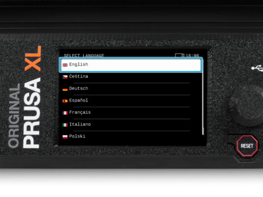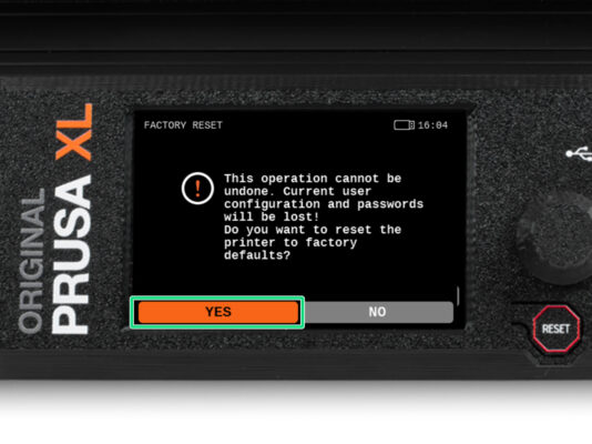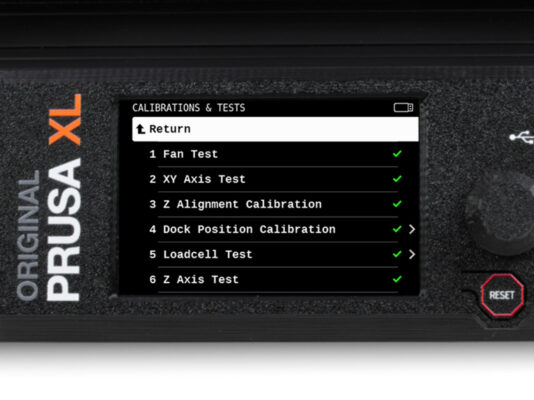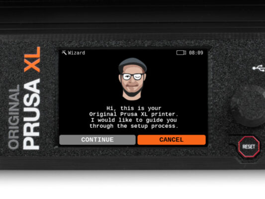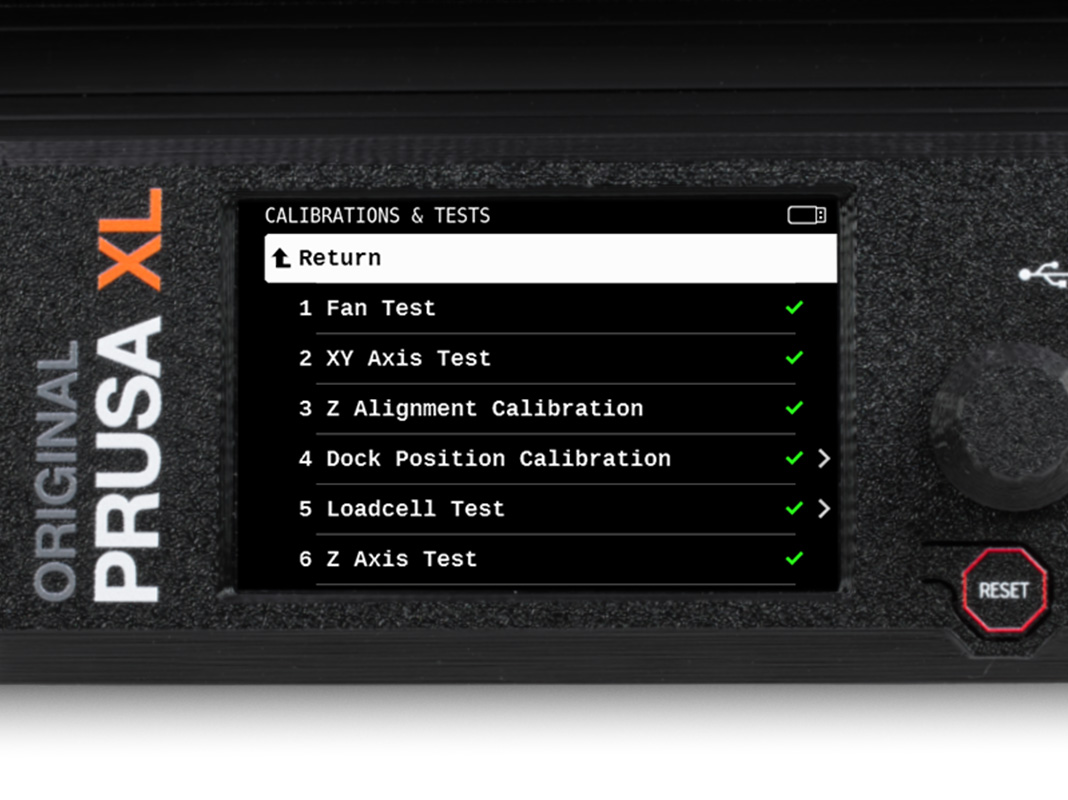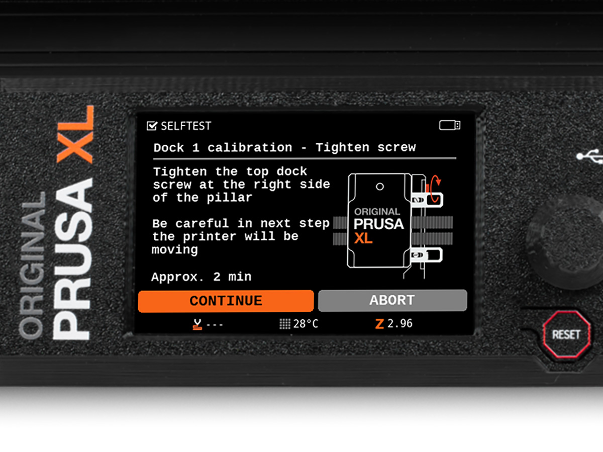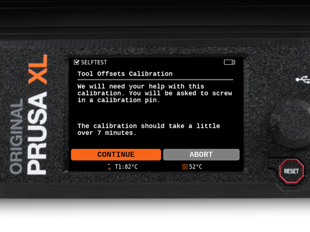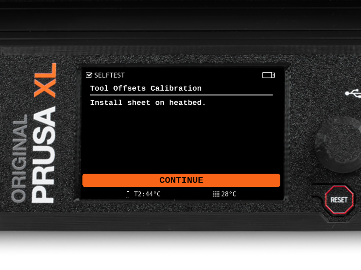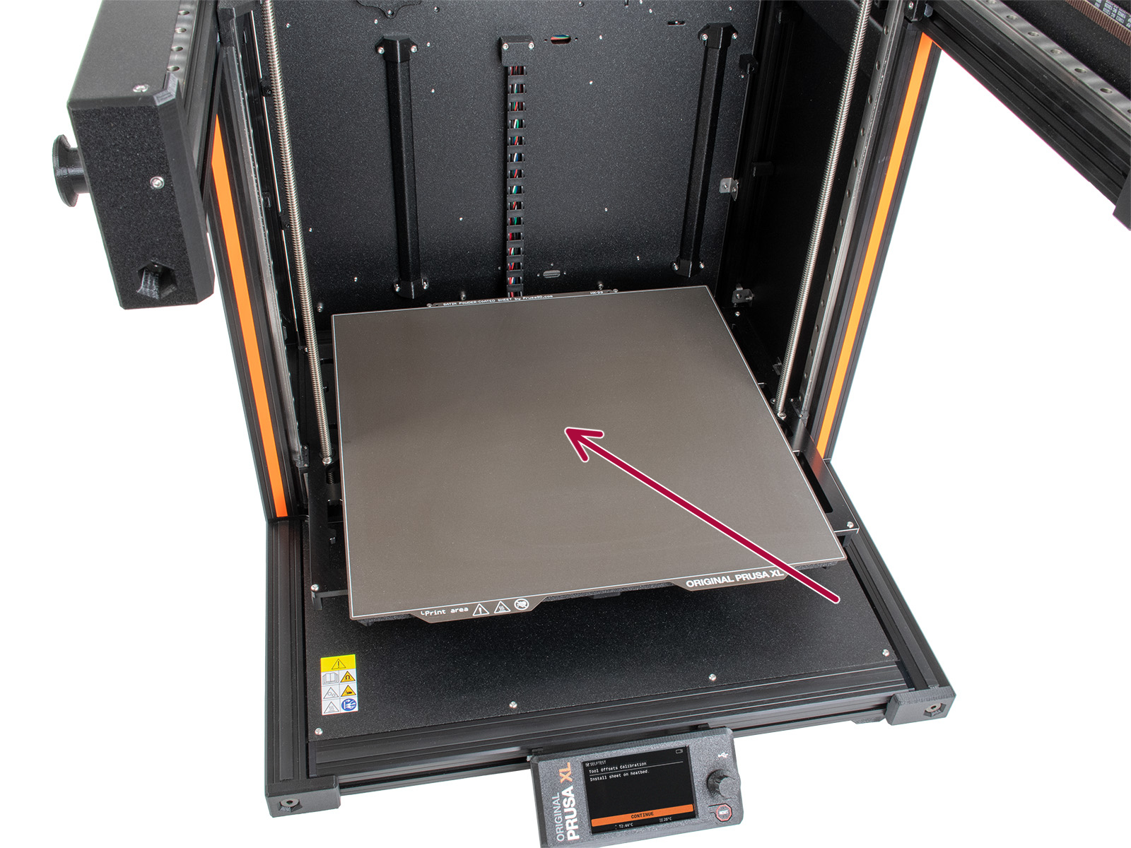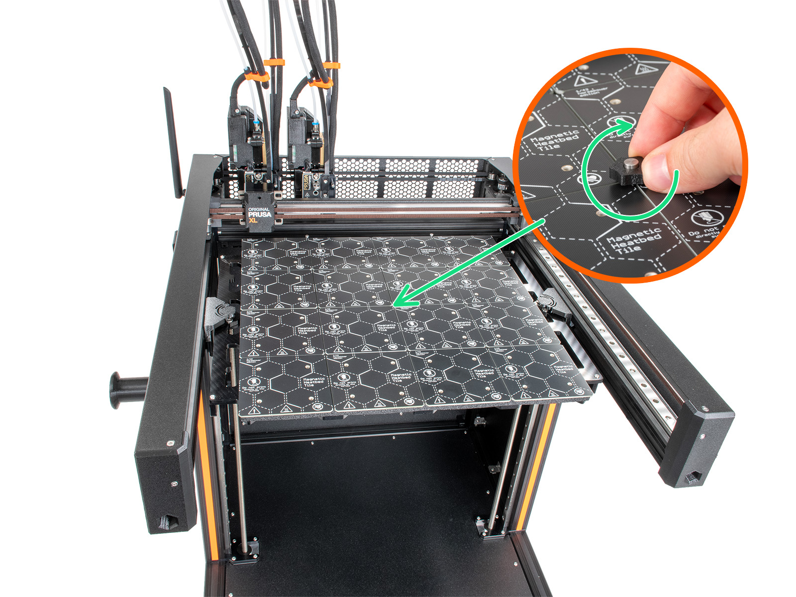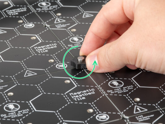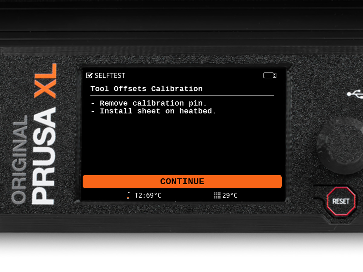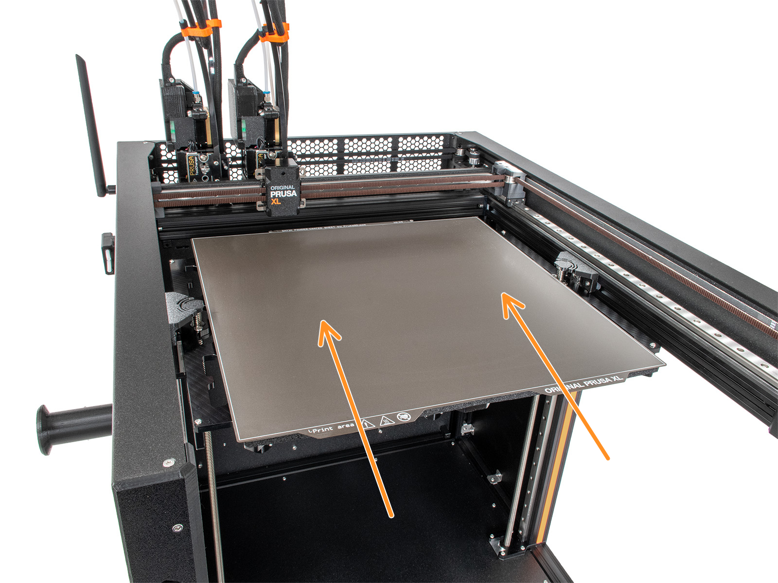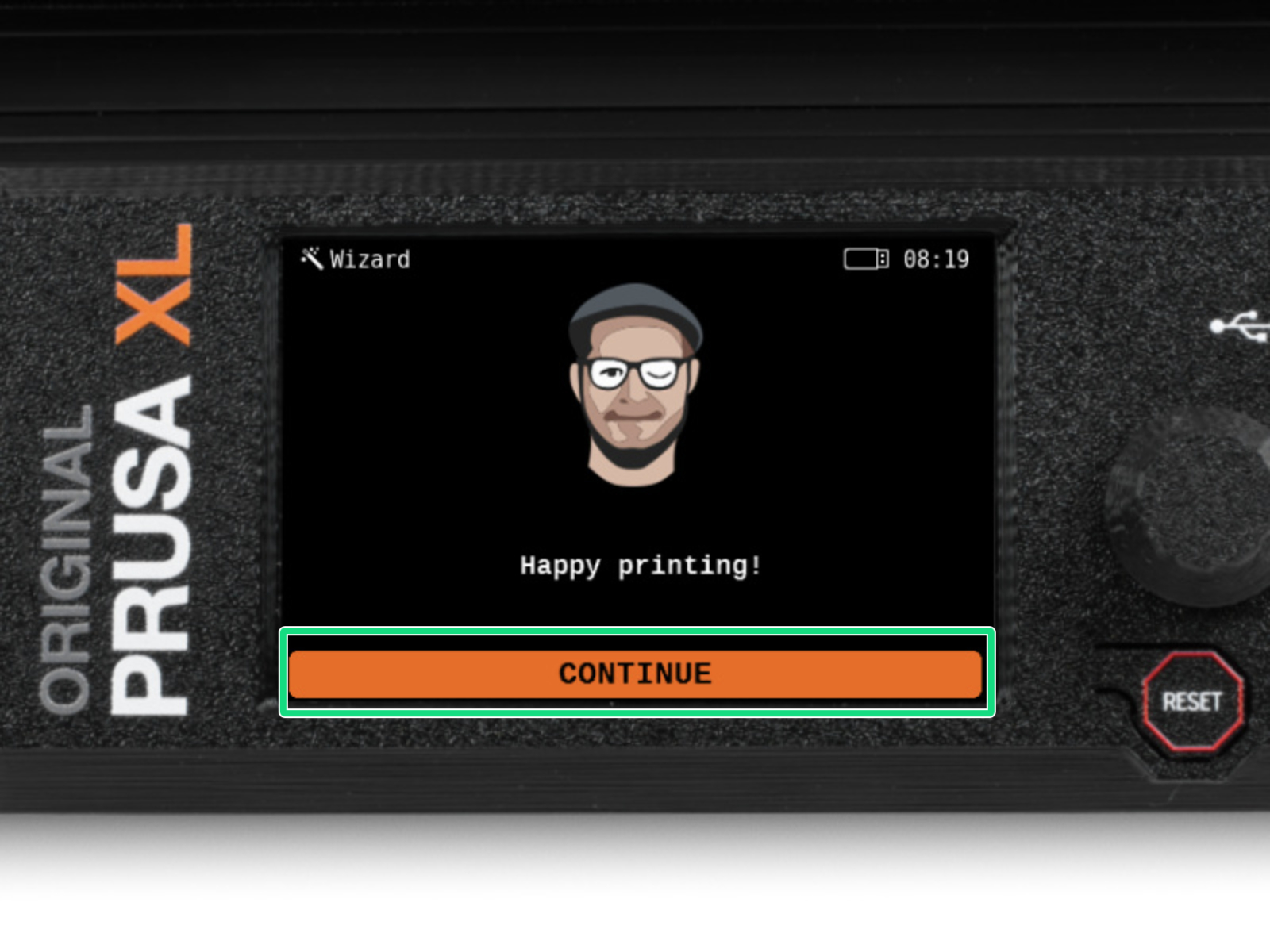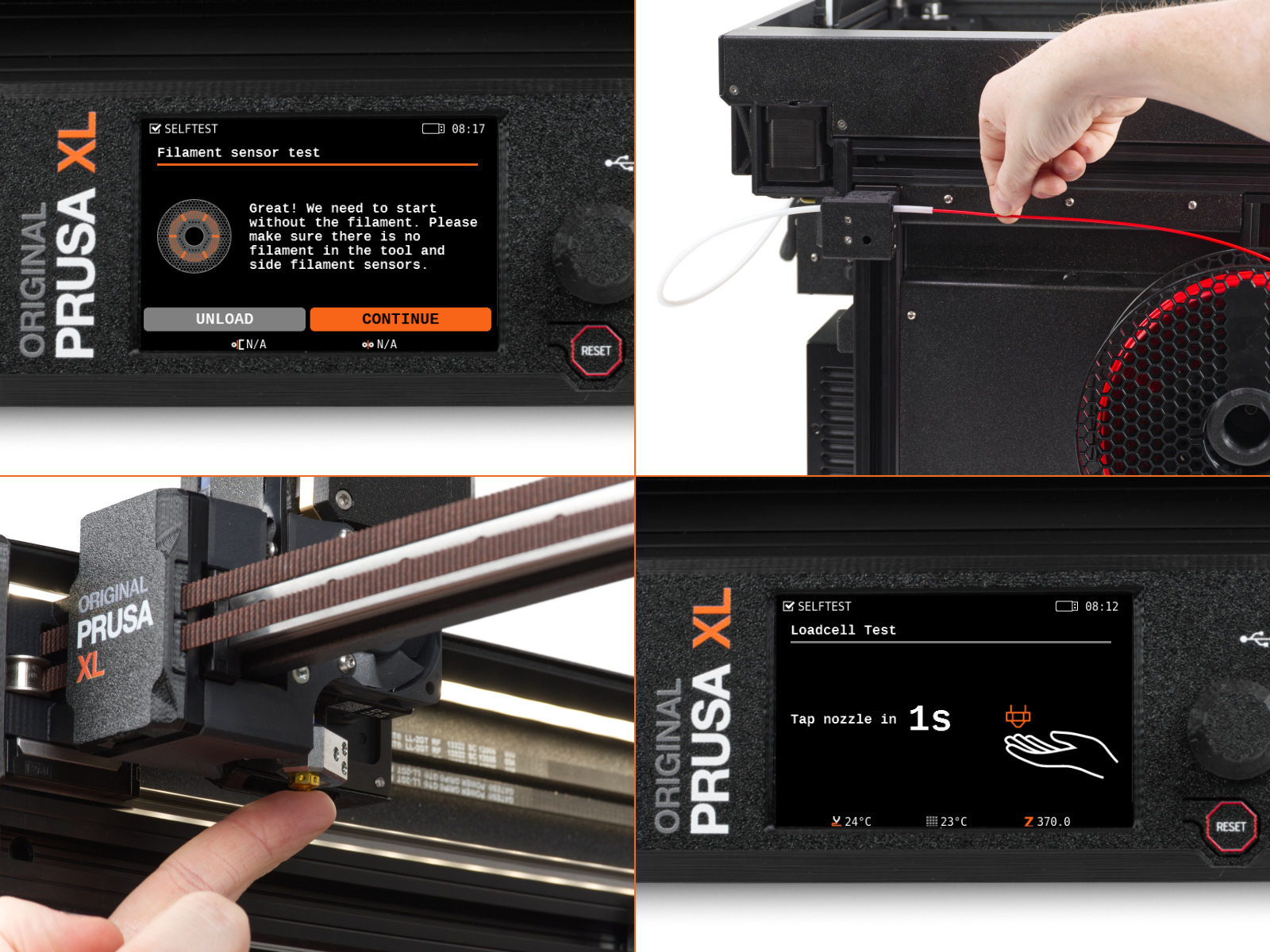
This chapter shows a brief description of the wizard. Please note that the screenshots are illustrative and might differ from those in the firmware.
Make sure you are running Firmware 4.7.0 or newer
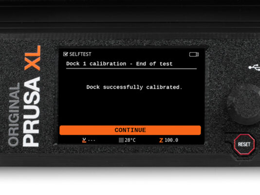
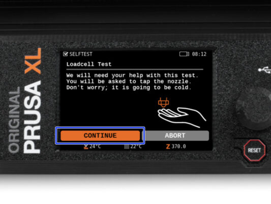
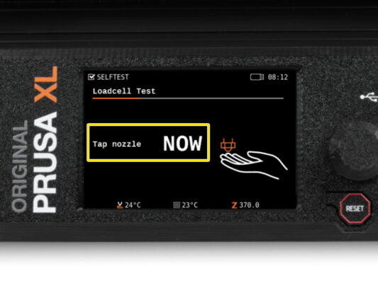
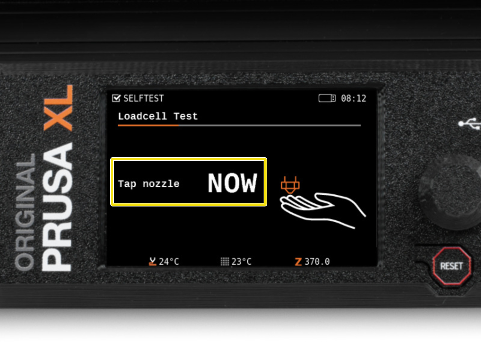
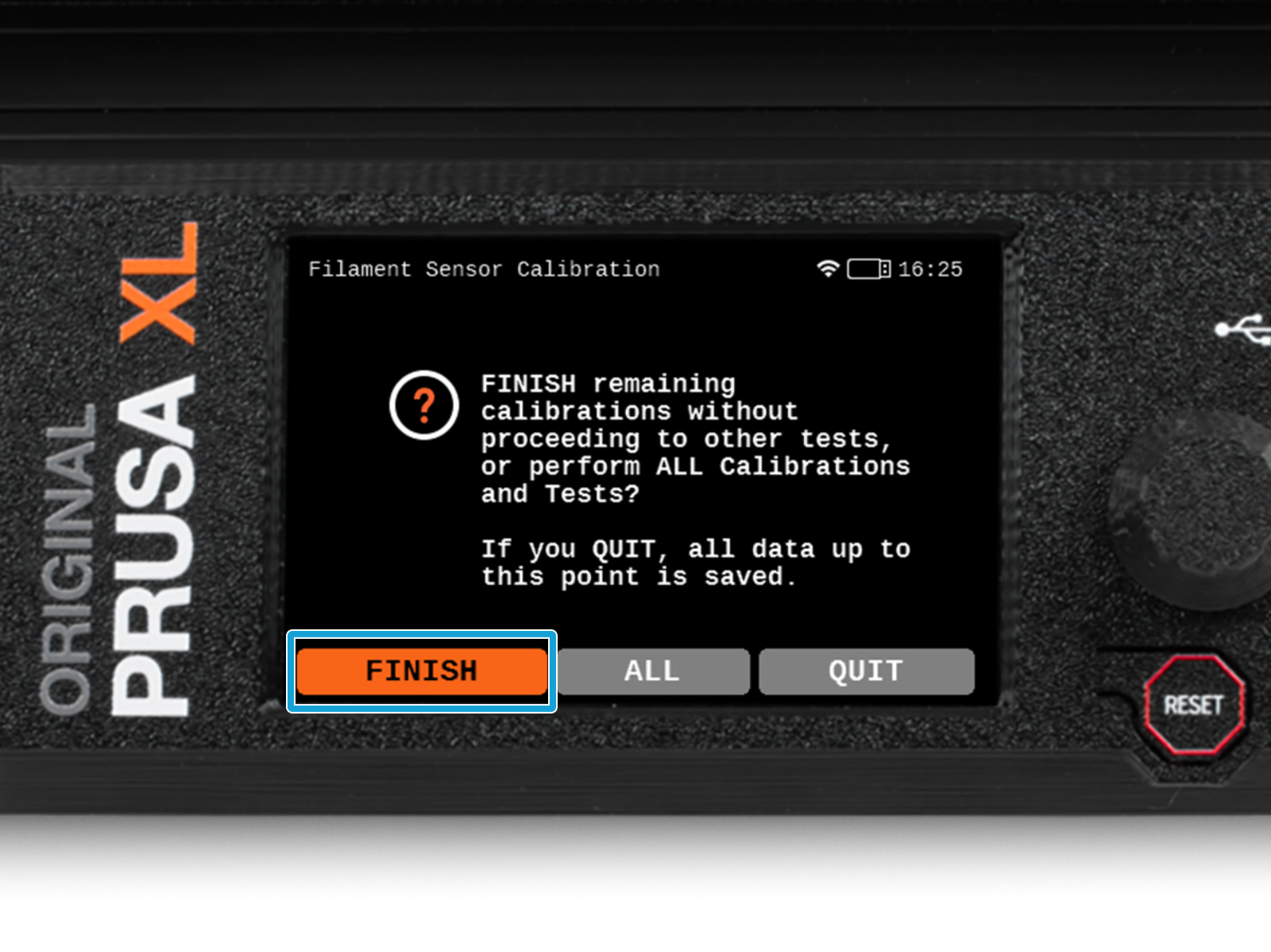
Some parts of the wizard must be done multiple times, this depends on the number of tool-heads. For example:
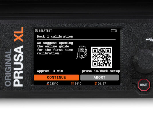
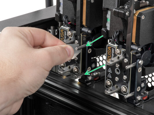
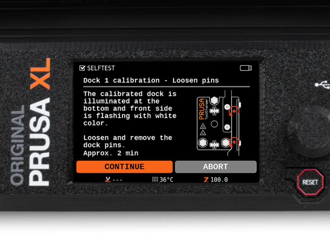
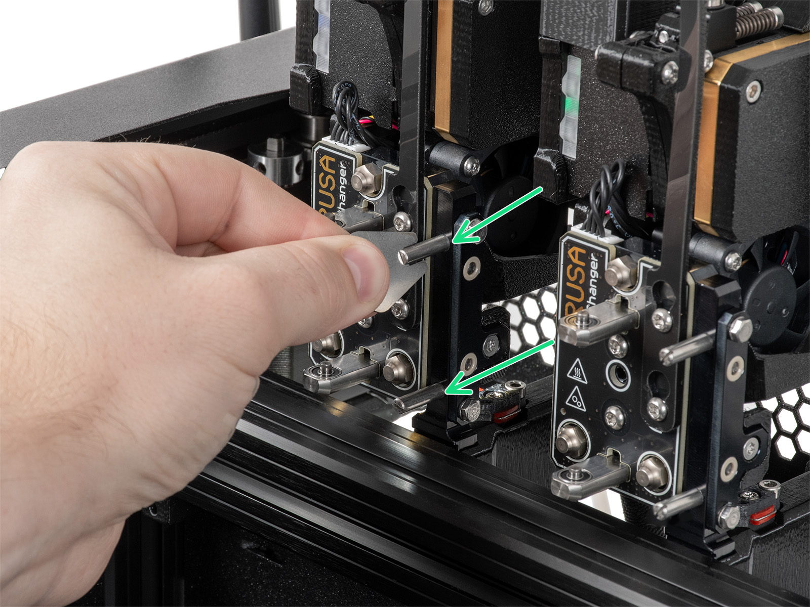
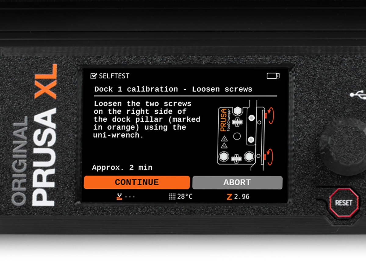
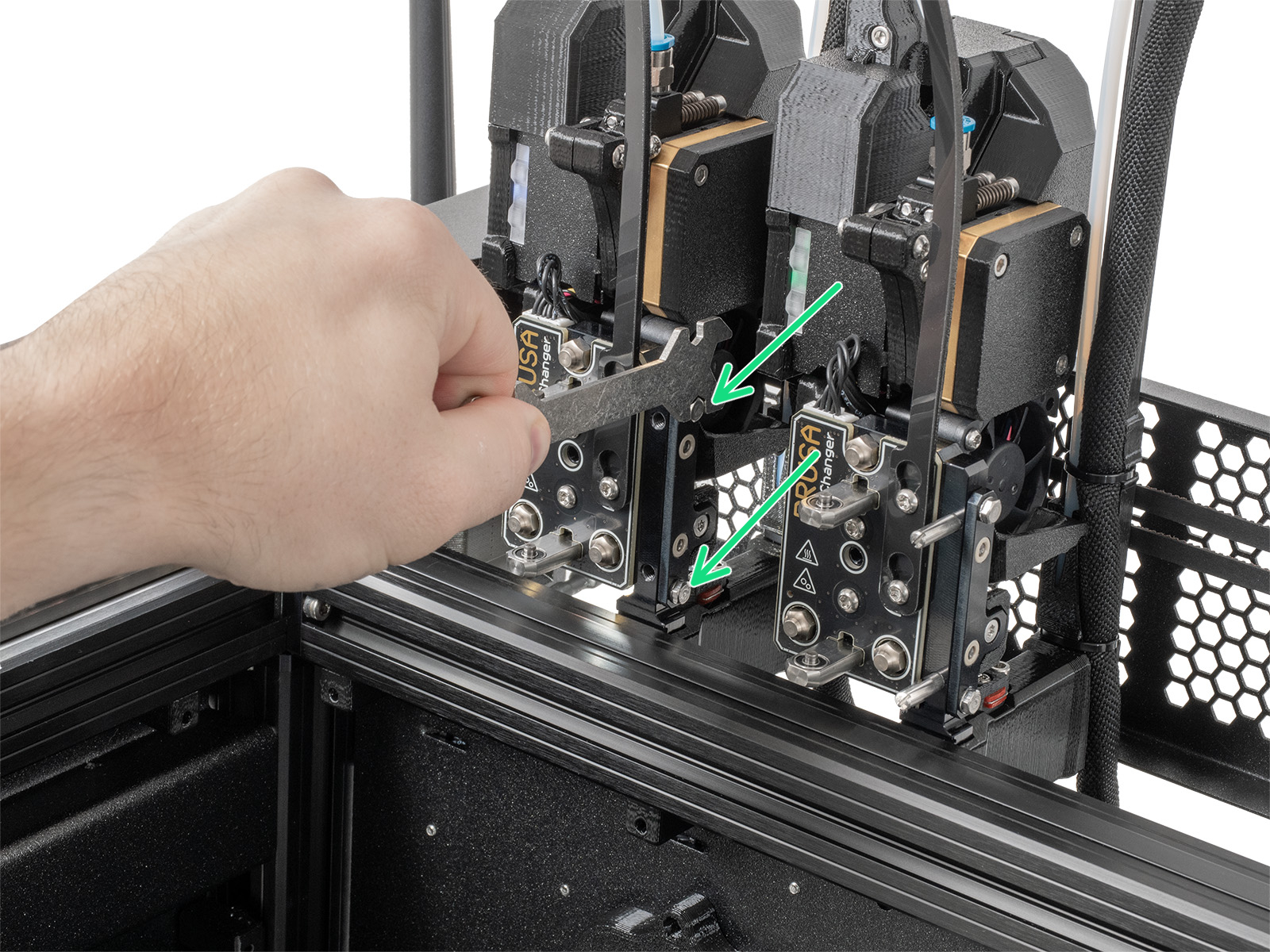
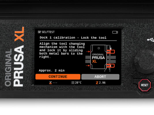
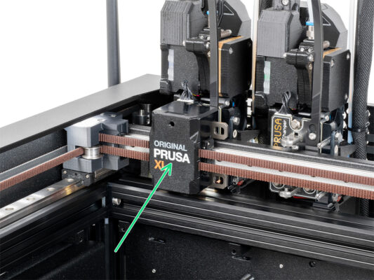
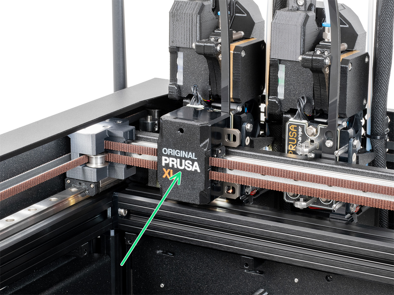
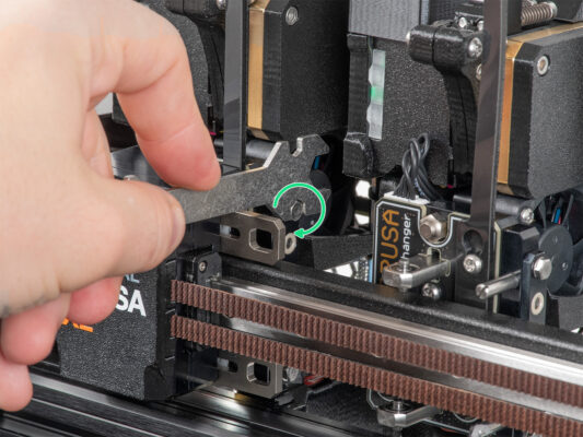
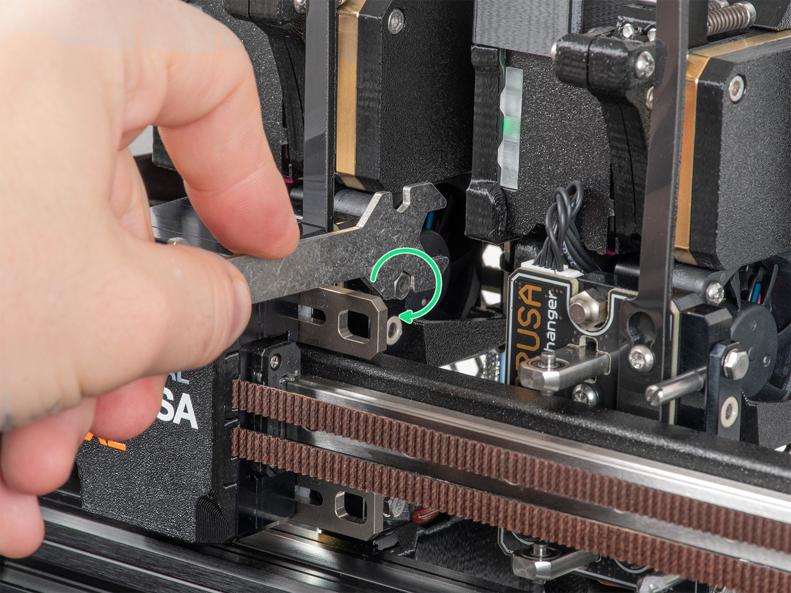
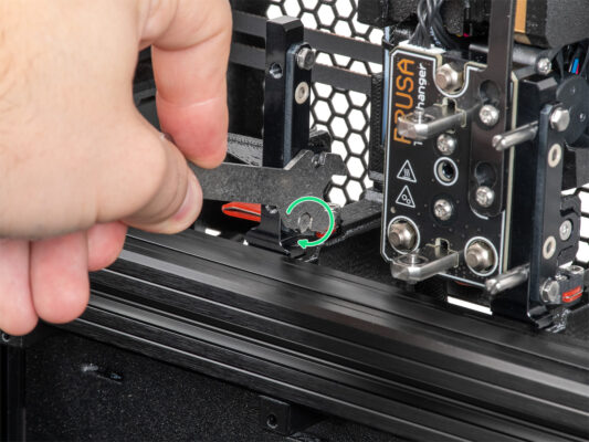
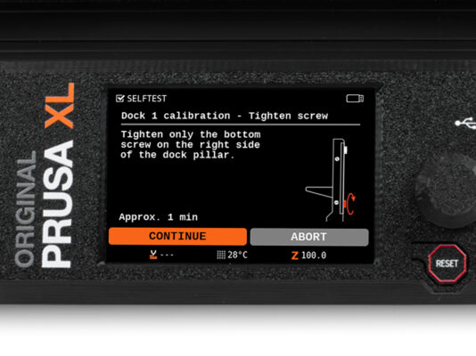
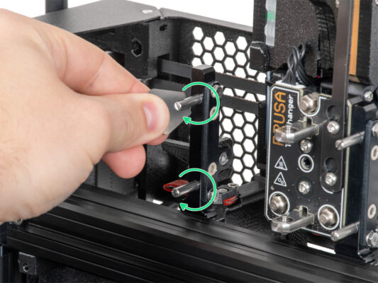
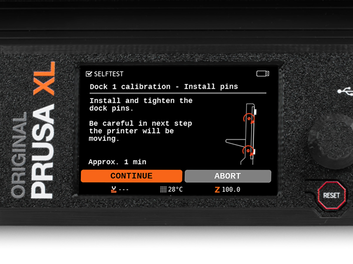
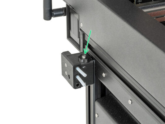
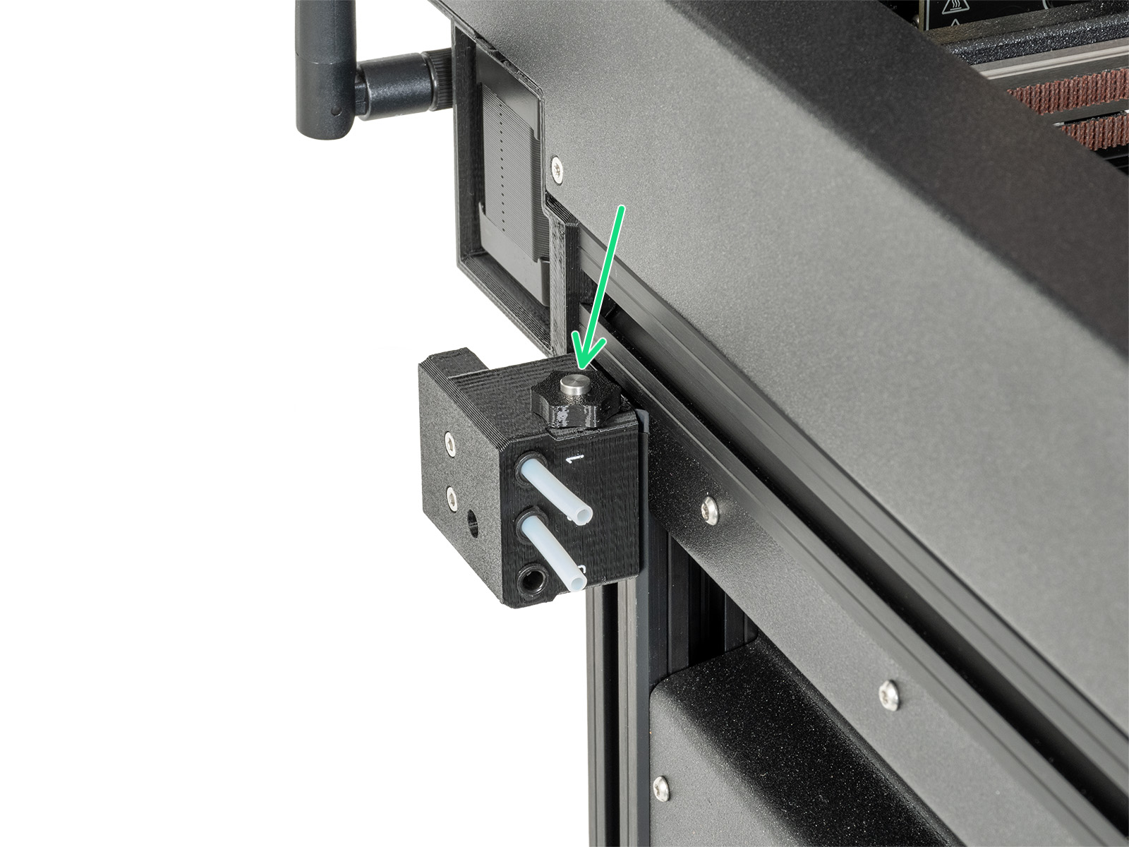
⬢Dock Calibration
⬢Loadcell calibration
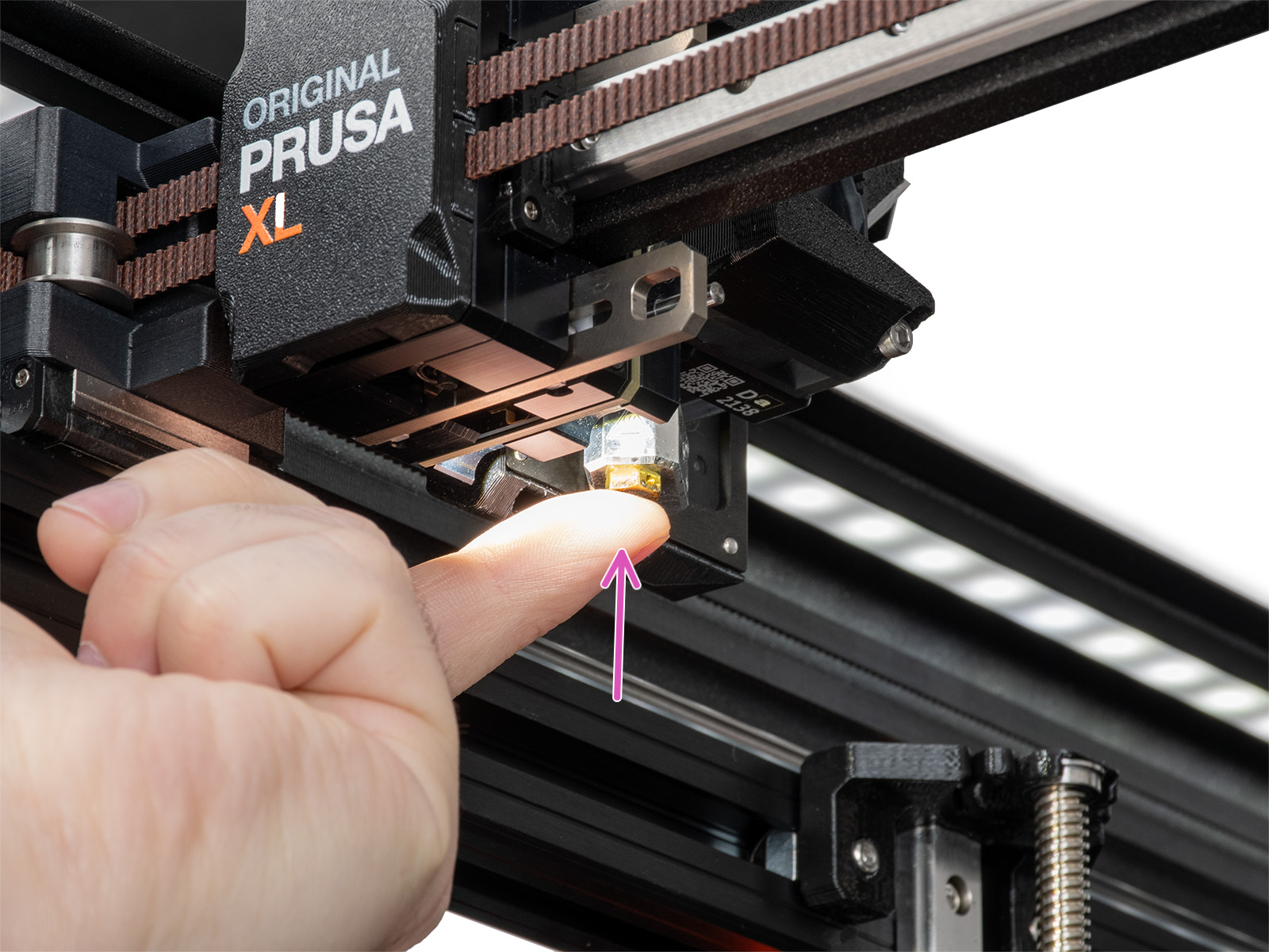
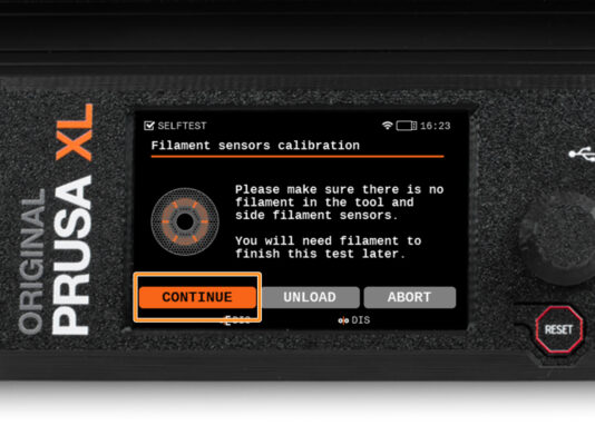
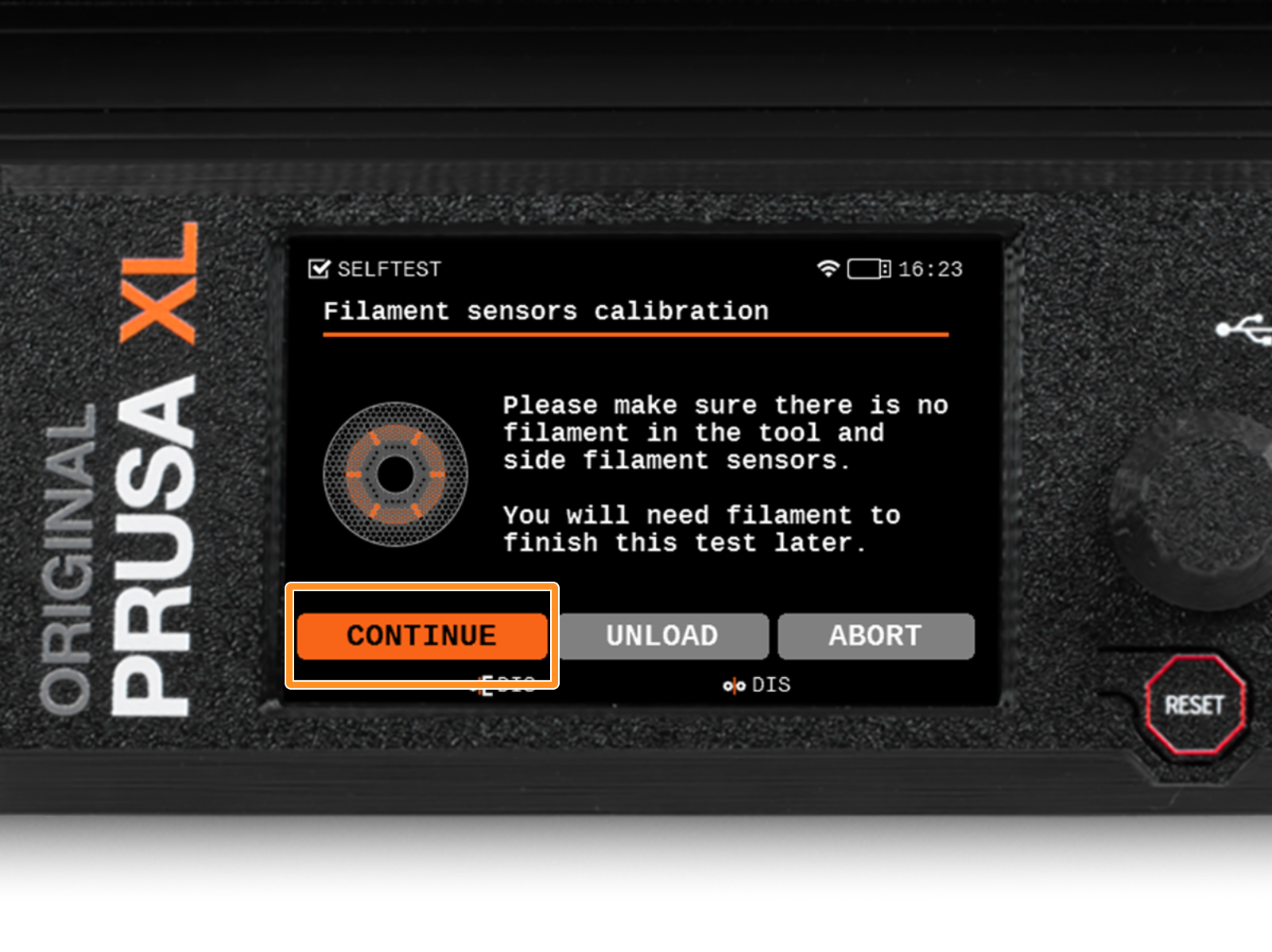
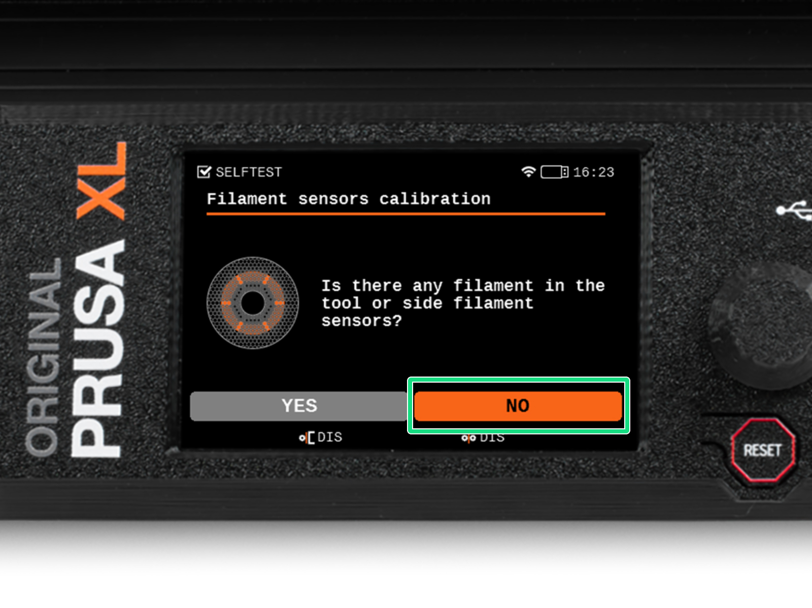
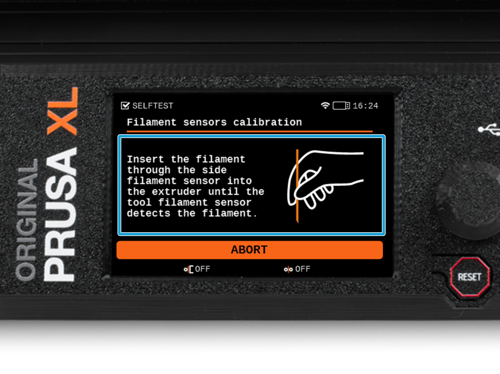
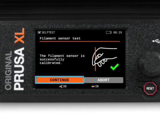
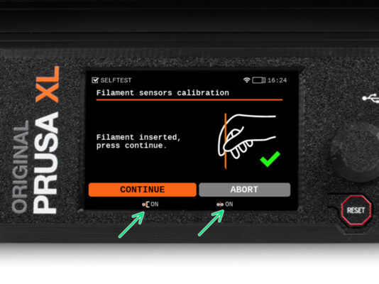
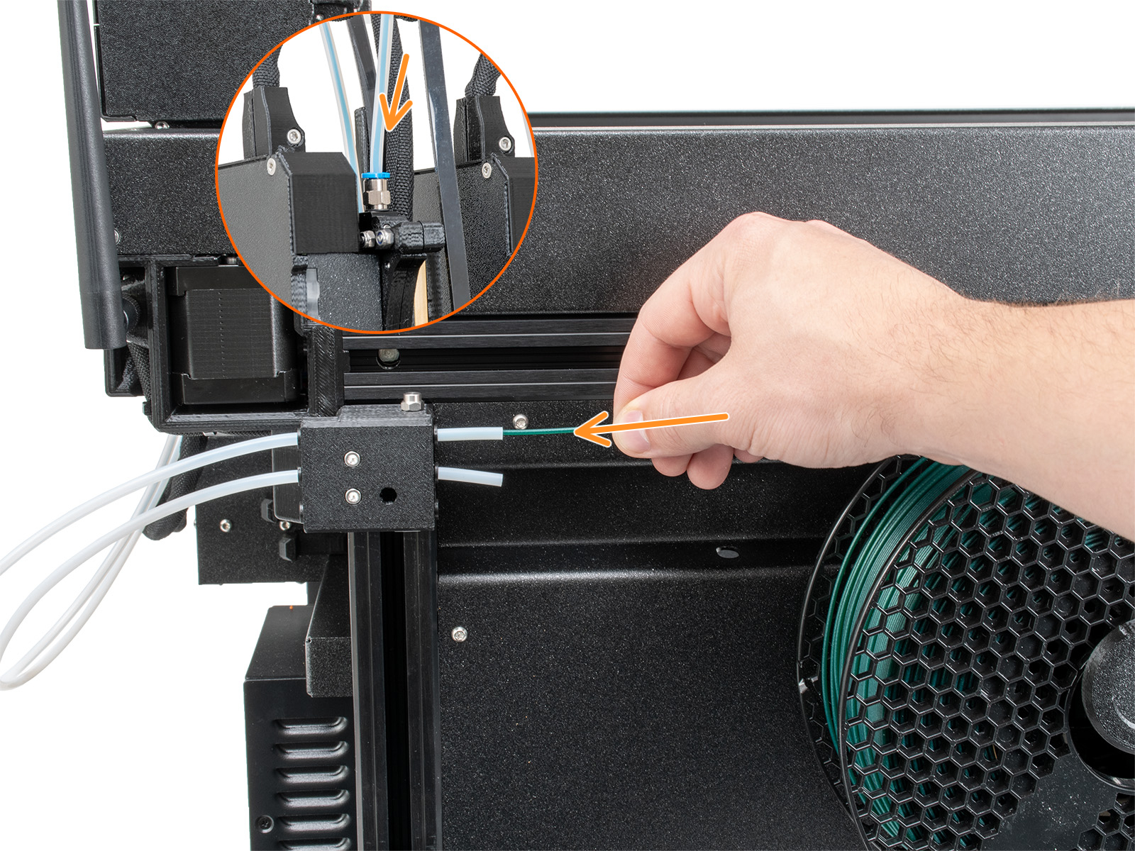
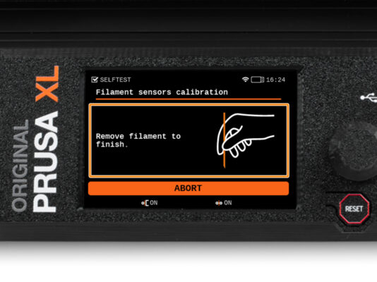
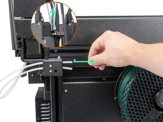
⬢Filament sensor calibration