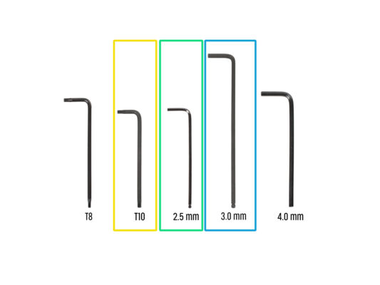
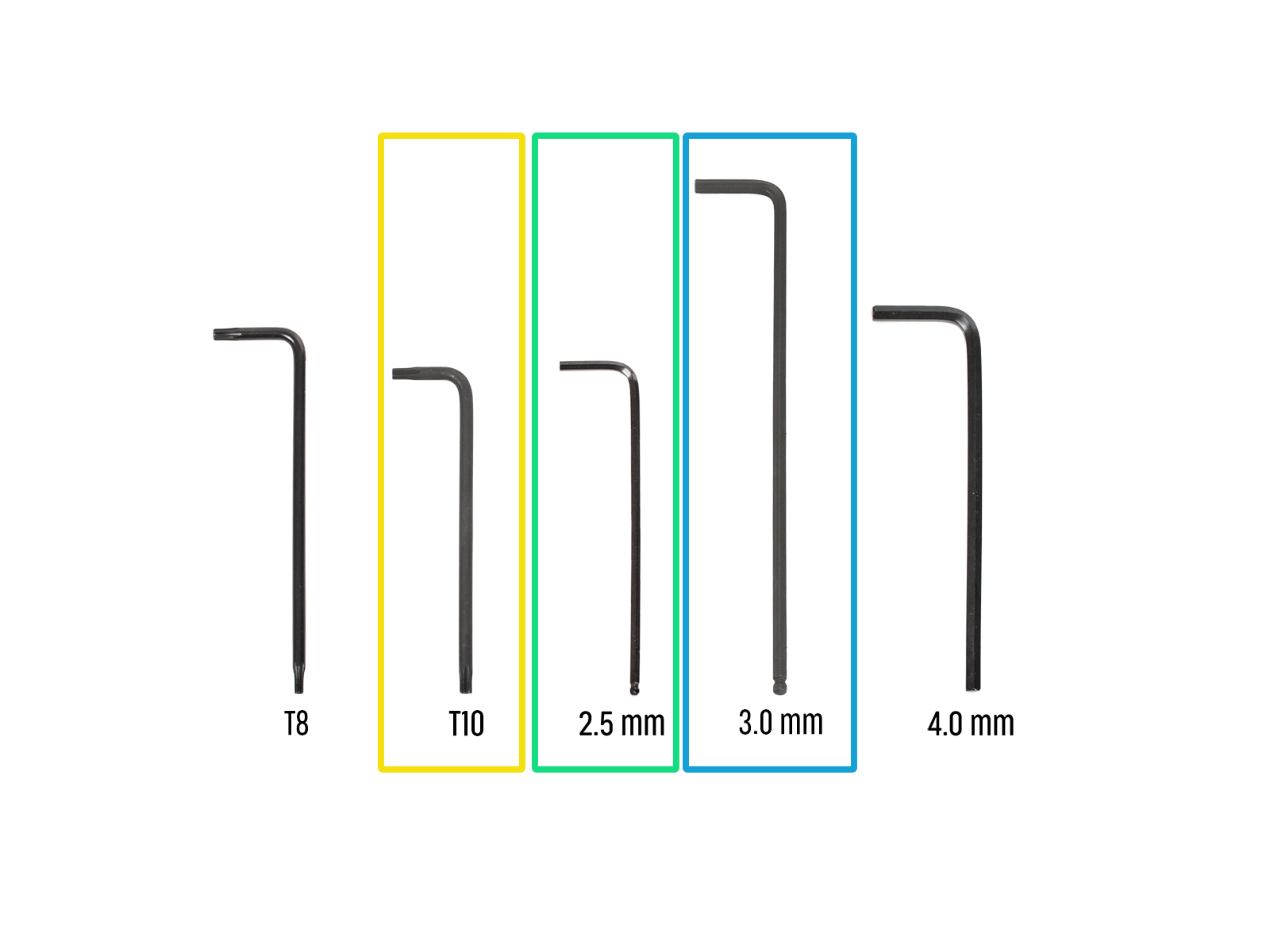
EN
  • Čeština
  • Español
  • Italiano
  • Deutsch
  • Polski
  • Français
Login

5. Nextruder & accessories assembly

5. Nextruder & accessories assembly

5. Nextruder & accessories assembly
Relevant for:
Last updated 2 months ago
5. Nextruder & accessories assembly
 Difficulty
Moderate
 Steps
35
 Available languages
CSPLDEESITFR
Right filament sensor
From the right side of the printer:
Insert the M3nEs nut into the extrusion.
Connect the filament sensor cable to the filament sensor.
Insert and tighten the M3x10 screw using a 2.5 mm Allen key.
You should now have both Side Filament sensors attached.
Guiding the Nextruder cable
Carefully turn the printer 180° so that the PSU (Power Supply Unit) side is towards facing you.
Locate the long metal profile with five M3 holes inside the rear aluminium extrusion and push it to the left.
We'll use all M3 holes in the metal profile.
Maintain the position of the long metal profile for the next step. It must not move!
Version A: Attaching the Nextruder docks
If you have older docks, attach them to the first and the second positions. Then attach the new docks from the upgrade.
Place the xl-dock-cable-router on the bottom metal sheet below the aluminum extrusion.
Push the 2.5 mm Allen key all the way through the hole in the rear metal sheet until you reach the middle screw in the xl-dock-cable-router and tighten the screw.
The dock is a press fit, the screw MUST be tightened firmly.
Repeat this step for the second dock..
Version B: Attaching the Nextruder docks
If you have older docks installed in the first and the second dock position, continue attaching the docks from the third position.
Place the xl-dock-cable-router on the bottom metal sheet below the aluminum extrusion.
There is a protruding screw from the xl-dock-cable-router. Attach the screw to the first screw hole on the long metal profile. Through the hole in the rear metal sheet, check if the cable holder is lined up with the hole.
Push the 2.5 mm Allen key all the way through the hole in the rear metal sheet until you reach the middle screw in the xl-dock-cable-router and tighten the screw.
The dock is a press fit, so the screw needs to be tightened very hard.
Attach all the remaining docks using the same procedure
Dock inspection
Dock inspection
Dock inspection
Check that the docks are properly tightened. The dock must not move. 
The dock is a press fit, so the screw needs to be tightened very hard.
The following instructions need to be done correctly and carefully. Achieve better understanding and successful assembly by watching the video alongside the guide.
Version A: Nozzle seal: parts preparation
The following instructions are intended only for printers without pre-installed nozzle seals. If you have already installed the nozzle seals on the Nextruder docks, go to Connecting the Nextruder cables
For the following steps, please prepare:
Nozzle seal (2x)
The spring does not always have to be fitted on the nozzle seal. In this case, take the spring on the M3x30 screw in the nozzle seal. It is always included in the bag.
Version A: Installing the Nextruder nozzle seal
The current nozzle seal position is temporary, the exact height will be set later in this chapter.
The docks have a hole for a nozzle seal.
Insert the nozzle seal (with the spring) into the dock.
Using a 2.5 mm Allen key, tighten the screw so that the head of the screw is 1 mm above the dock.
Good! The first dock is ready.
Repeat this procedure for the second dock.
Connecting the Nextruder cables
Locate the xl-rear-cable-management-plug (cover) on the rear of the printer.
Loosen two screws on the cover slightly. No need to remove them completely. Push the cover to the right and remove it from the printer.
Loosen four screws securing the electronics cover. Remove the cover.
Connect the first dock (from the right side) cable to the upper slot labeled DWARF 1.
Connect the second dock (from the right side) cable to the lower slot labeled DWARF 2.
Wi-fi antenna holder versions
The antenna connector is prepared by the manufacturer:
Version A: The Wi-fi antenna holder is on the side. Continue to the step Connecting the side Wi-Fi antenna
The antenna connector has to be assembled by you:
Version B: The Wi-fi antenna is in the middle. Continue to the next step.
Installing the rear Wi-Fi antenna holder
This step is only for the printer, which has a Wi-Fi antenna on the back of the printer. If you have the antenna on the side of the printer, proceed to the next step.
Push the antenna cable through the opening in the cable cover (metal sheet) and guide it behind the cover to the electronics box.
Attach the antenna-holder on the screws and push the cover to the left and tighten the screws.
Connect the antenna to the apporpiate slot on the XL Buddy board.
Connecting the Nextruder cables
Do not take the XL-splitter board out of the printer, the photo is only a tool for connecting the Nextruder cables.
Connect the third, fourth and fifth (from the right) Nextruder to the splitter:
Third Nextruder.
Fourth Nextruder.
Fifth Nextruder.
XL-splitter with connected Nextruders has to look like this.
XL buddy box covering
Be carefull, do not pinch any cables!
Put the XL-buddy-box-cover back on the printer.
Check Nextruders cables, they have to be inside the cutout in the cover.
With a T10 key tighten the four screws.
Guiding the docks PTFE tubes
Locate the right filament sensor.
Insert the first dock (from the right side) PTFE tube all the way into the upper hole in the part.
Insert the second dock (from the right side) PTFE tube all the way into the middle hole in the part.
Insert the third dock (from the right side) PTFE tube all the way into the lower hole in the part.
Guiding the docks PTFE tubes
Locate the left filament sensor.
Insert the fourth dock (from the right side) PTFE tube all the way into the upper hole in the part.
Insert the fifth dock (from the right side) PTFE tube all the way into the middle hole in the part.
Installing the Wi-Fi antenna
This step is only for the printer, which has a Wi-Fi antenna on the back of the printer.
Locate the Wi-Fi antenna connector in the middle of the printer.
Screw the Wi-Fi antenna on the antenna connector. The antenna can be rotated around and bent in two directions.
We recommend pointing the antenna straight upwards.
Assembling the spool holder
Repeat this step for all three spool holders:
Locate pins two pins on the spool-holder-base and line them with the rails in the spool-holder-slider.
Insert the spool-holder-base into the spool-holder-slider and push it through a little through the part.
Preparing the spool holder
Insert the M4x12 screw on the longer side of the 3mm Allen key.
Insert the 3mm Allen key with the M4x12 screw through the assembled spool holder to the prepared hole in the spool-holder-base.
The M4x12 screw has to protrude through the spool-holder-base.
Spool holder: left side
Carefully turn the printer so that the side with the filament sensor (with 3 PTFE tubes).
Insert the third M4nEs nut in the extrusion approximately to the same position as shown.
The M4nEs nuts are free to move, you can adjust the position as you want. But remember, the nuts must be slightly pushed in to smoothly move. Anyway, we recommend approximately the same position as you can see in the picture.
Attach and tighten the third spool holder to the M4nEs nut using a 4 mm Allen key. Note that there is a protrusion on the spool-holder-mount, which must fit into the groove in the extrusion.
Do not use the spool holder as a handle!
Keep in mind that if you mount the Spool holder too high or too low, it may not fit the filament spool on it. There has to be enough space around it.
Spool holder: right side assembly
Turn the printer, so the Filament sensor (with two PTFE tubes) is facing you.
Insert the fourth and fifth M4nEs nut in the extrusion approximately to the same position as shown.
The M4nEs nuts are free to move, you can adjust the position as you want. But remember, the nuts must be slightly pushed in to smoothly move. Anyway, we recommend approximately the same position as you can see in the picture.
Attach and tighten the fourth and the fifth spool holder to the M4nEs nut using a 3 mm Allen key. Note that there is a protrusion on the spool-holder-base, which must fit into the groove in the extrusion.
Do not use the spool holder as a handle!
Keep in mind that if you mount the Spool holder too high or too low, it may not fit the filament spool on it. There has to be enough space around it.
How to dock the Nextruder
Take the Nextruder and place it carefully next to the dock.
Place the two metal inserts through the white holes in the dock. The magnets will help you dock the Nextruder.
Check that the Nozzle seal lightly touches the nozzle.
Well done, the first Nextruder is ready!
Connect the second, third, fourth and fifth Nextruder in the same way as the first.
Nextruder cable bundle assembly
Repeat this step for all tool heads:
Take the first dock Nextruder cable bundle.
Check that the cable bundle is not twisted!
Hook up the keyhole openings in the flexible plate of the cable bundle onto the screw heads and push it up to correct the position.
Using a T10 key tighten the marked two screws.
Nextruder cable bundle assembly
Repeat this step for all tool heads:
Attach the cable connector into the top of the Nextruder.

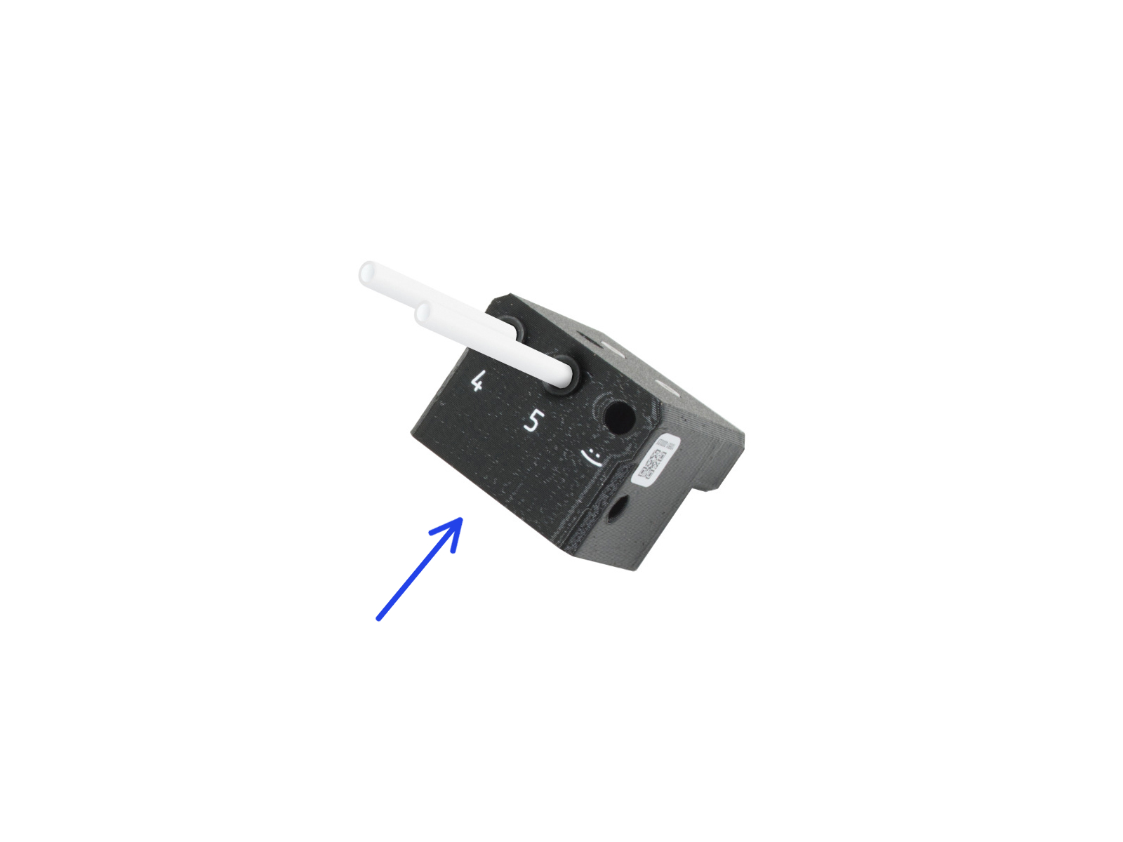
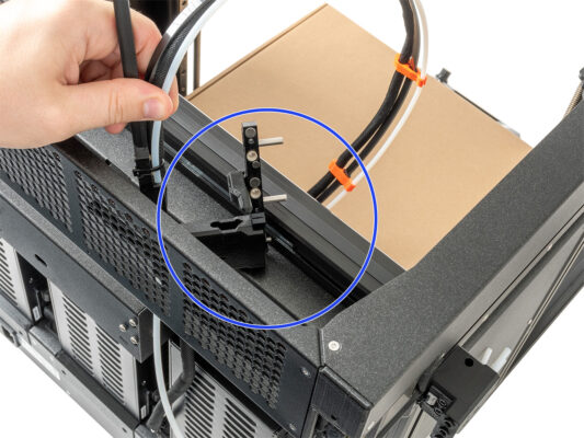
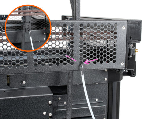
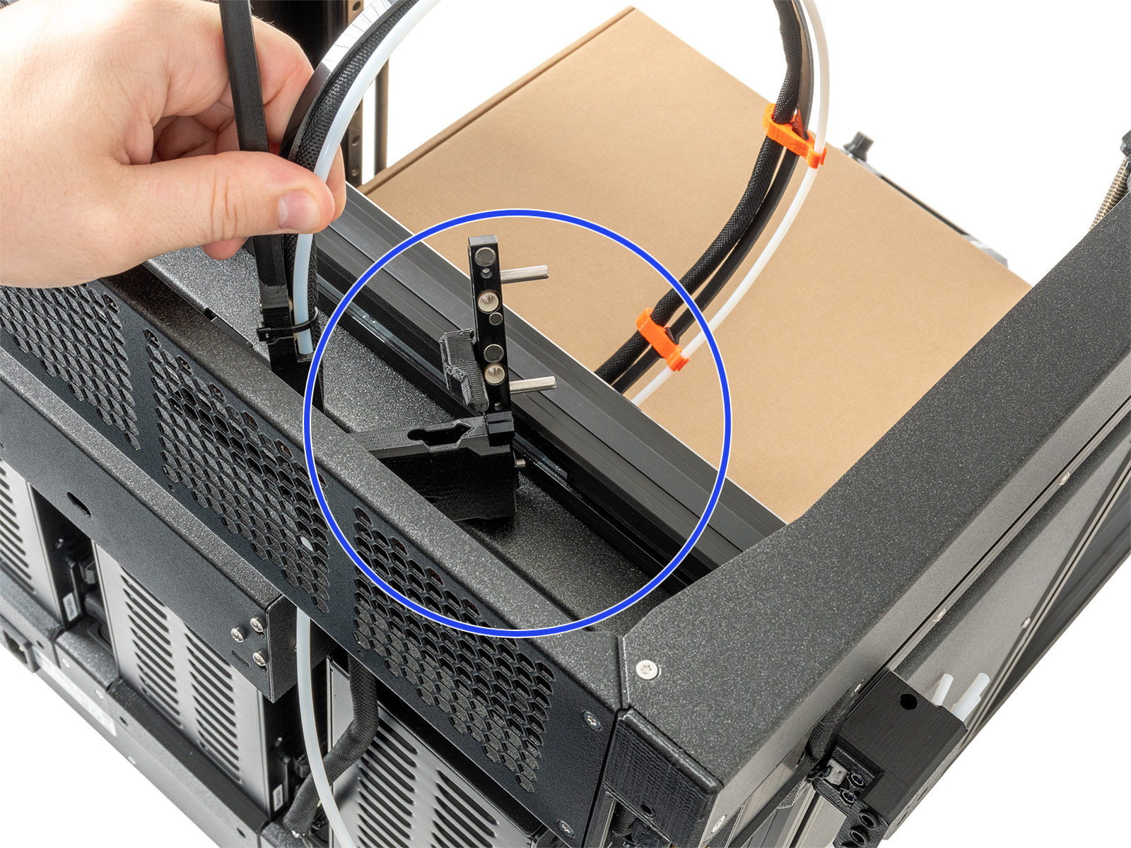
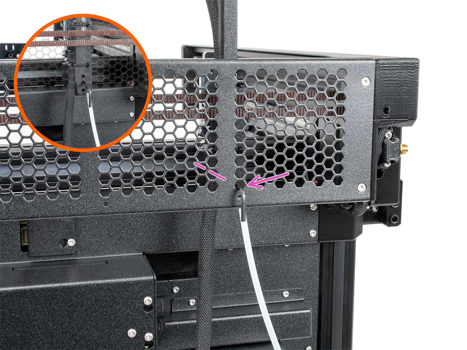
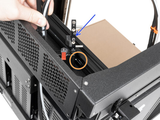
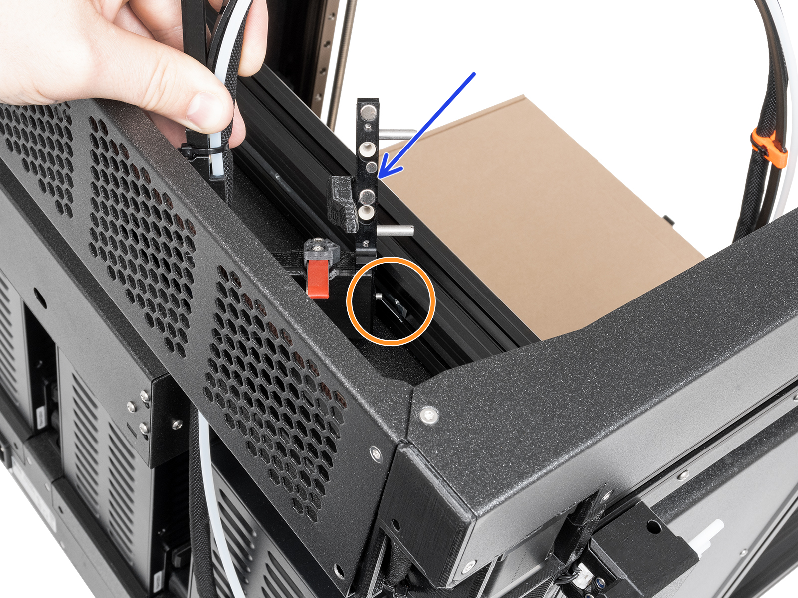
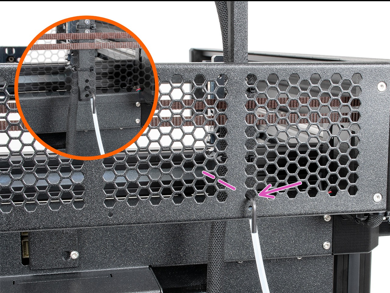
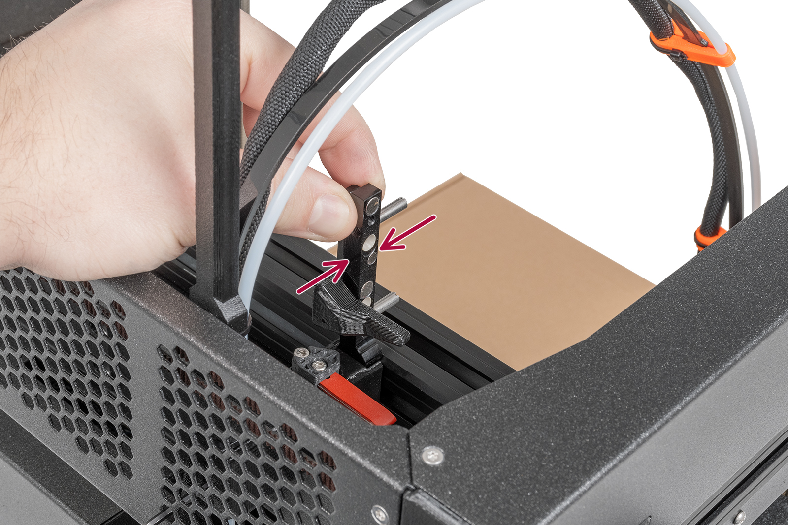
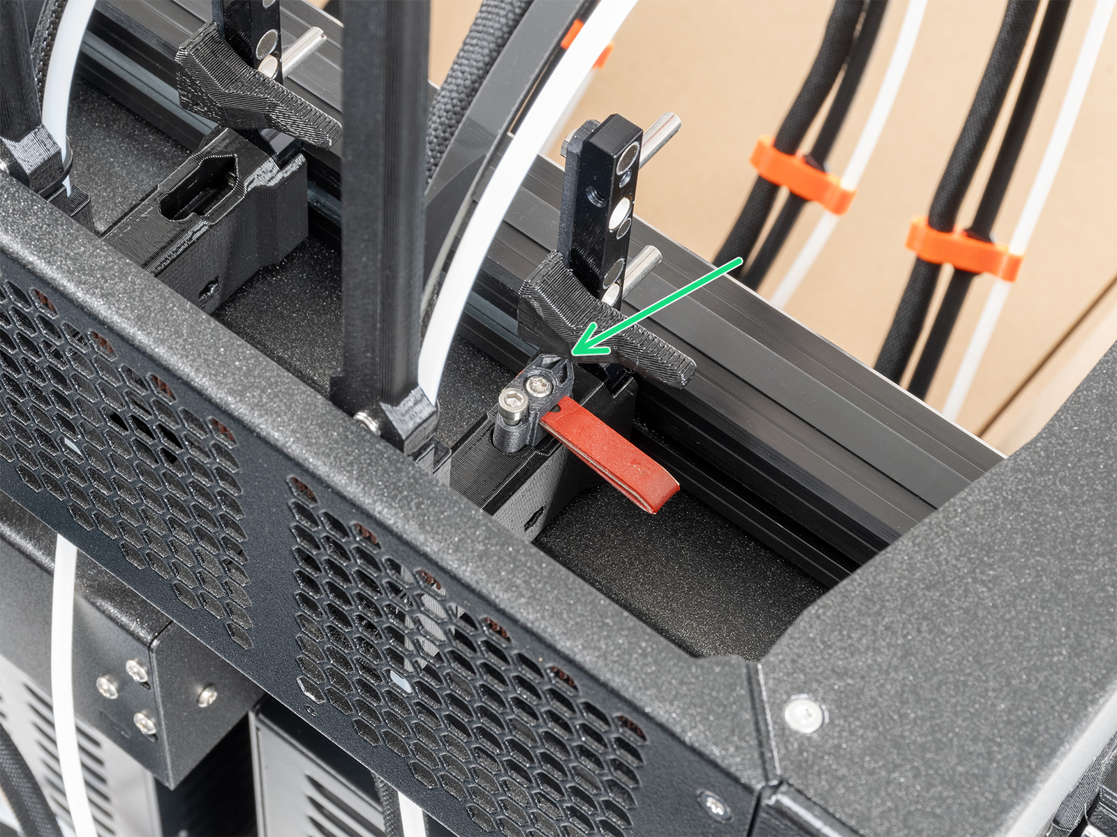
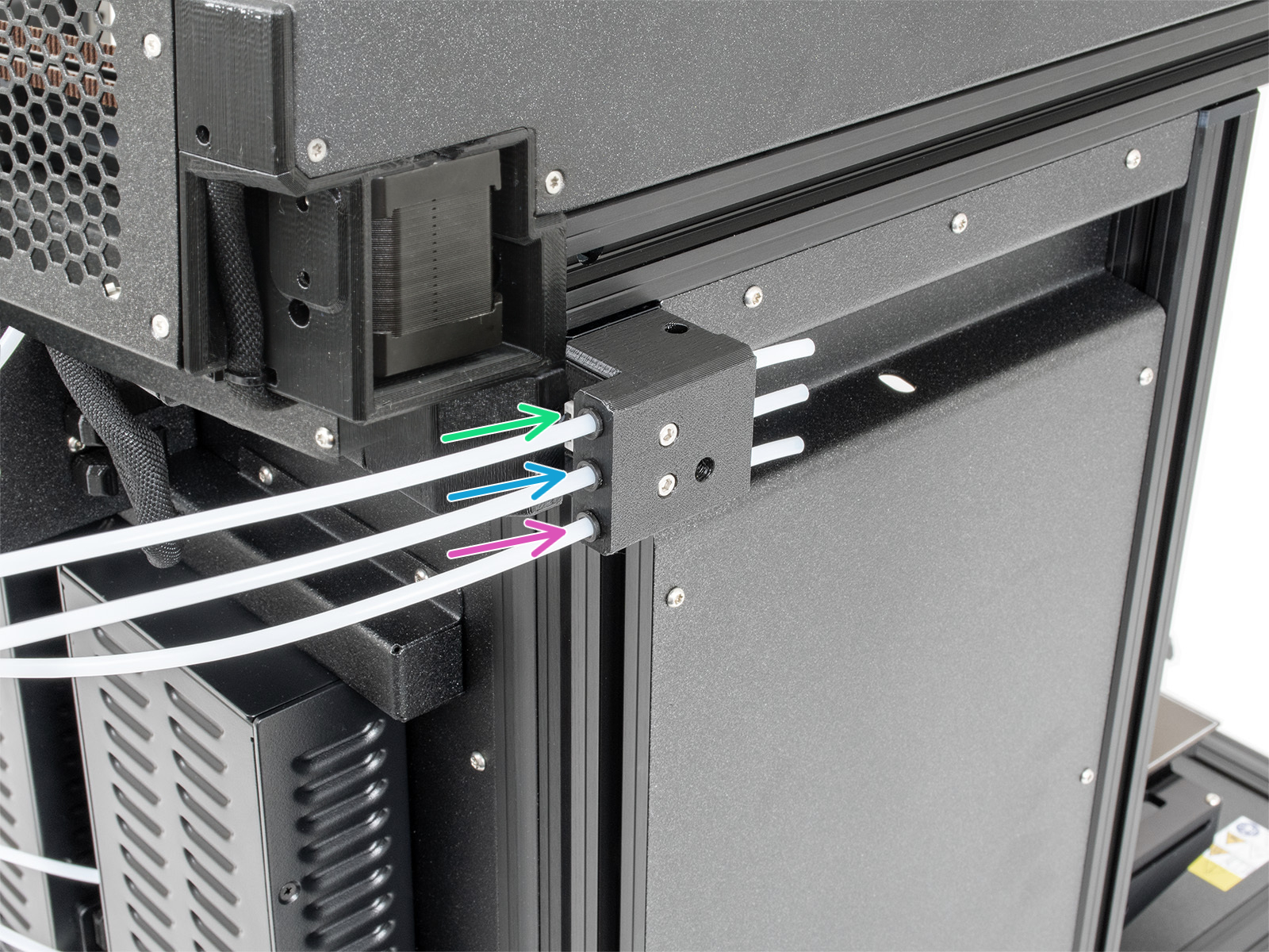
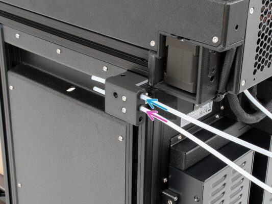
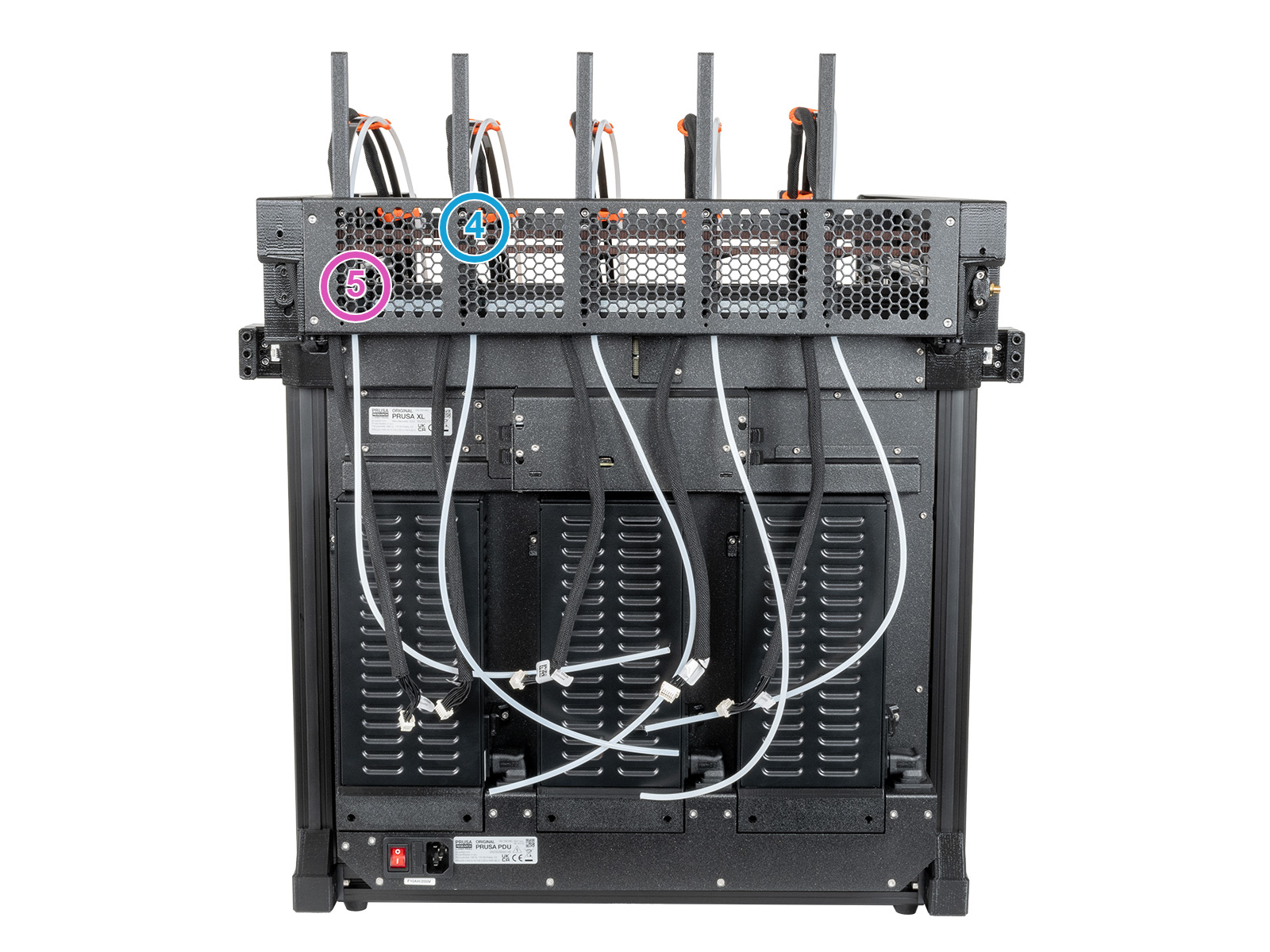
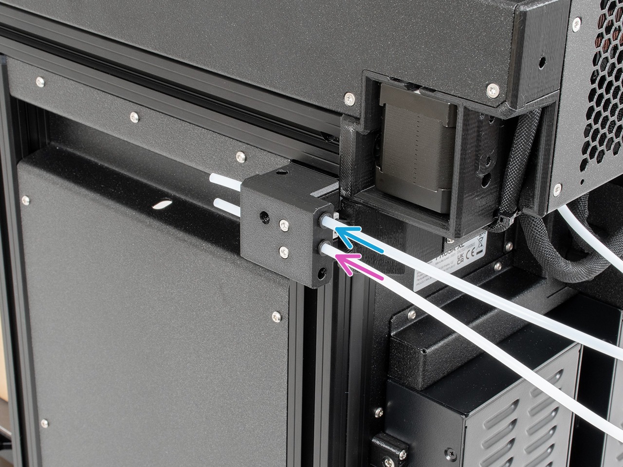
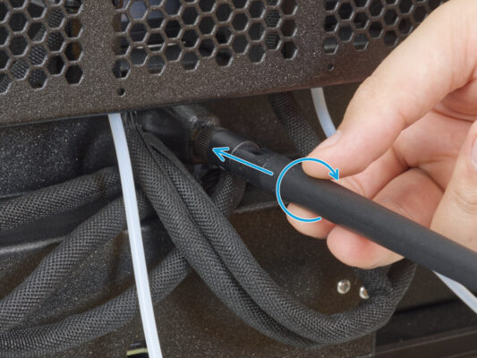
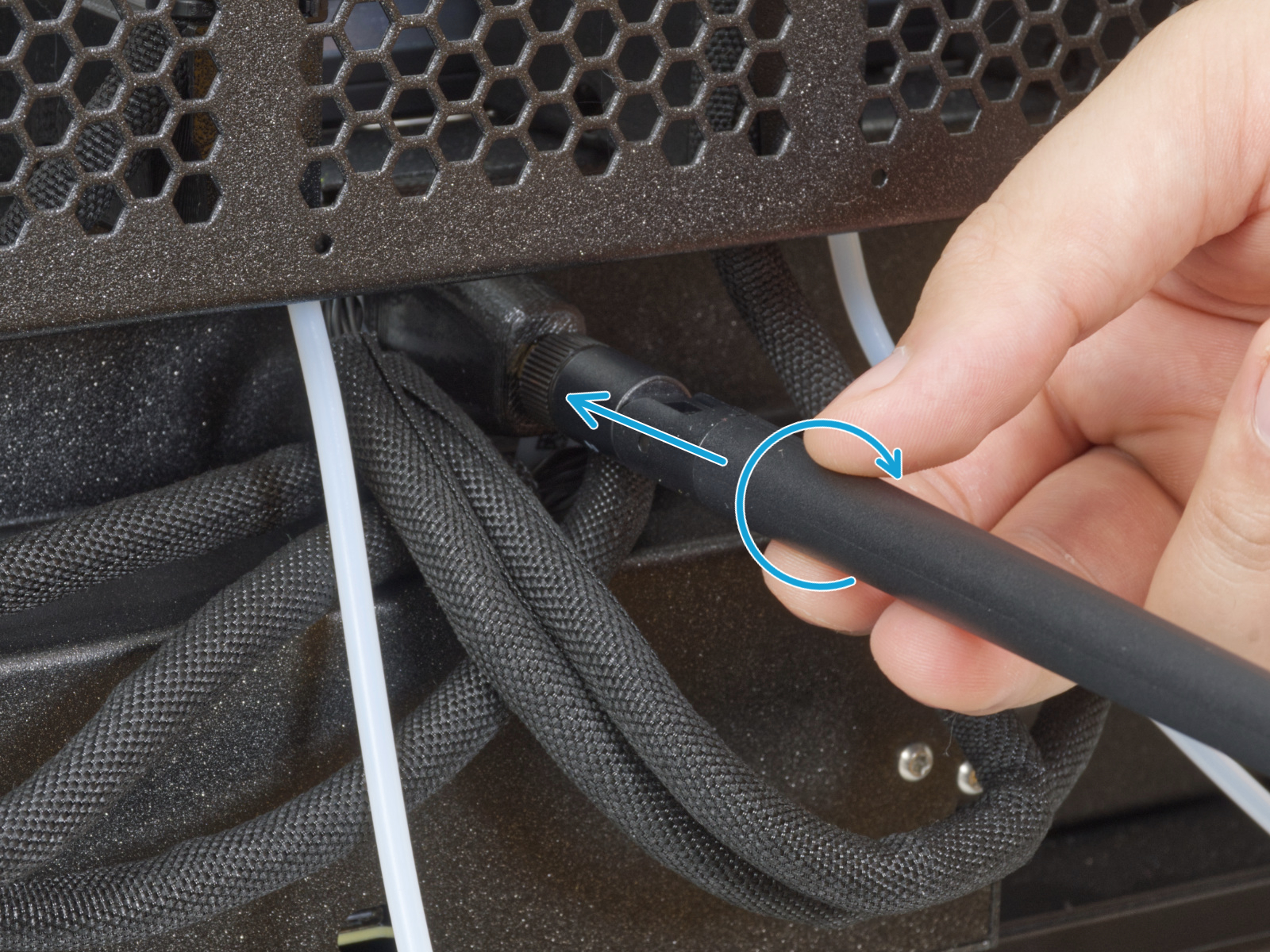
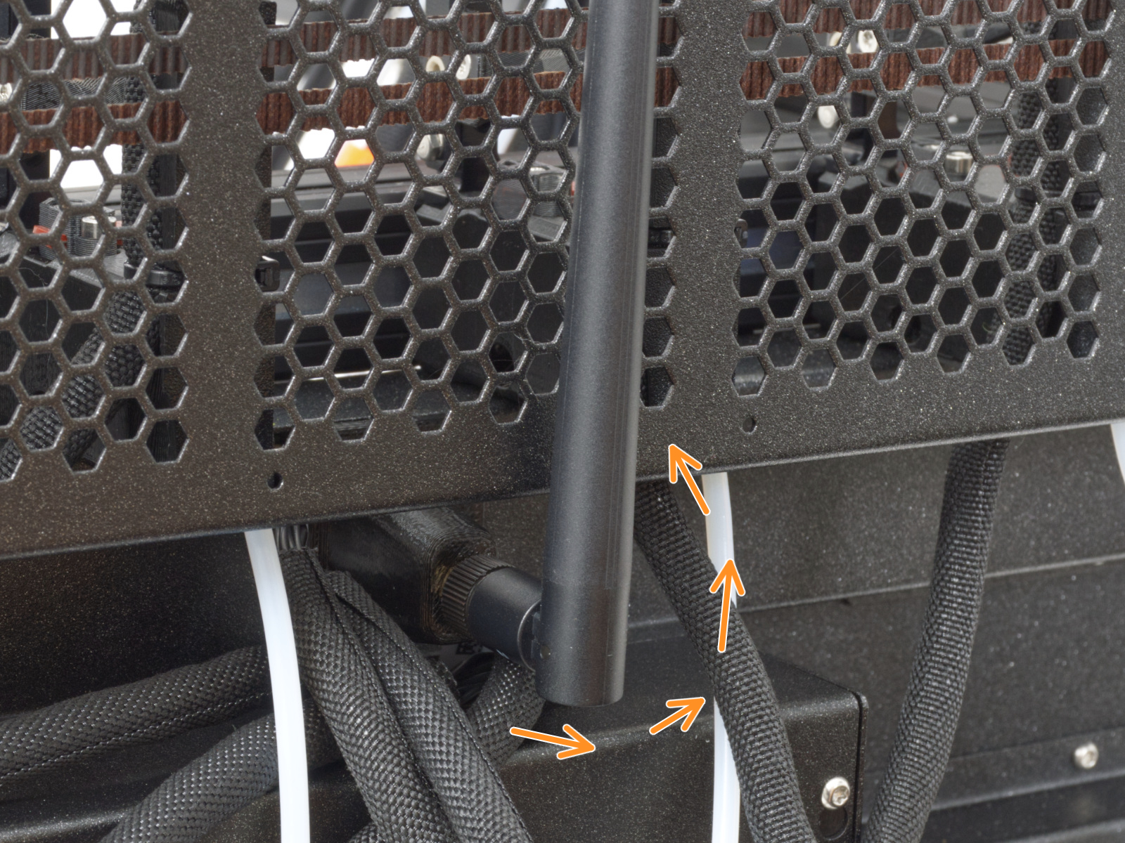
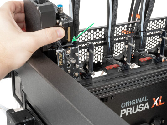
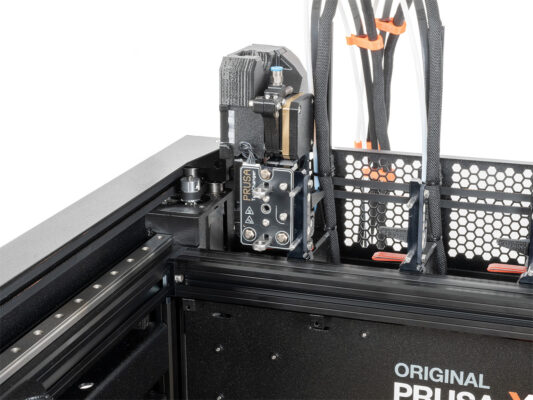
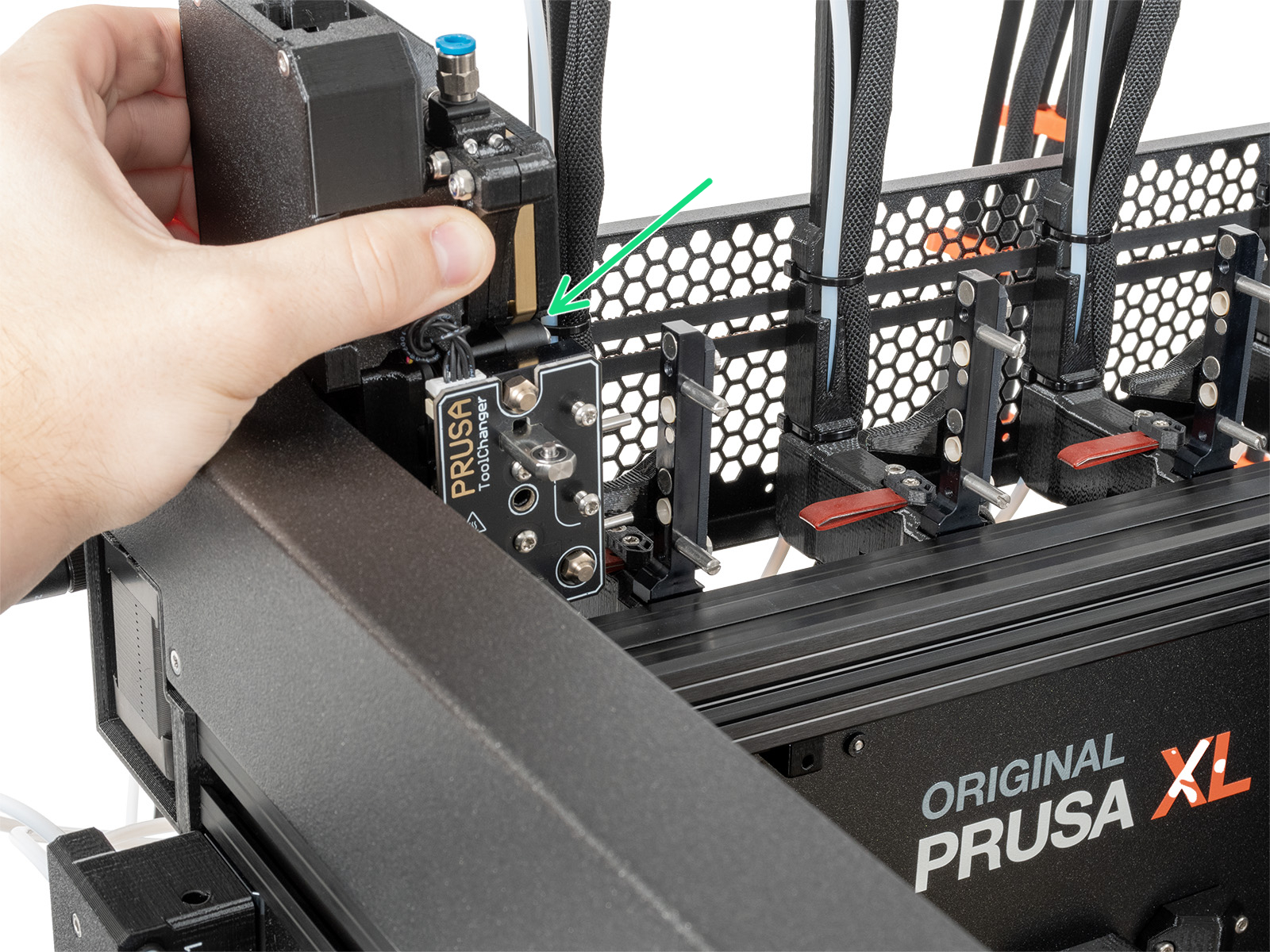
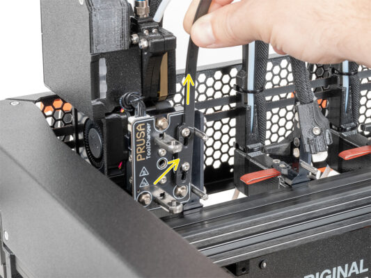
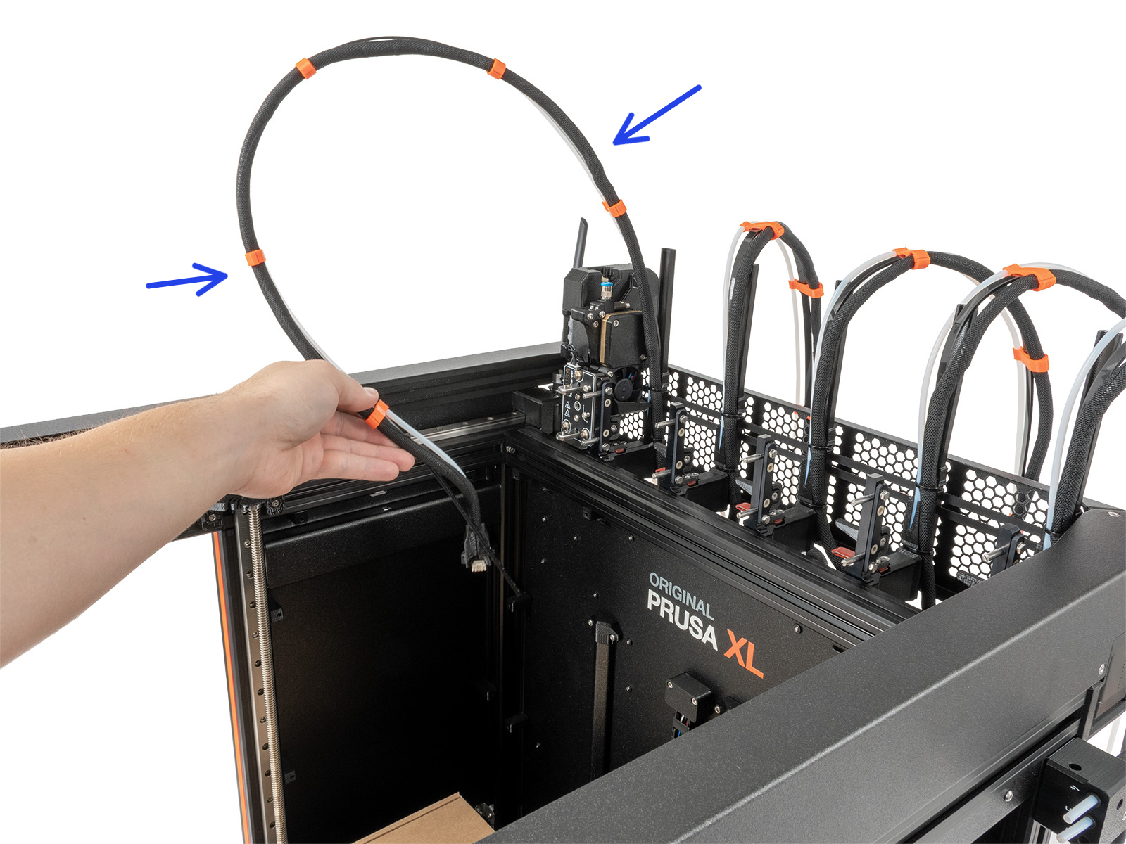
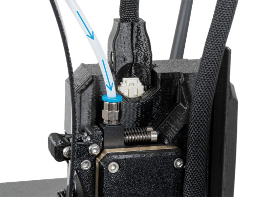
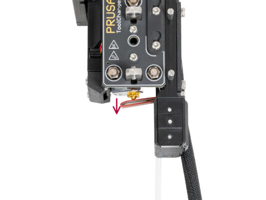
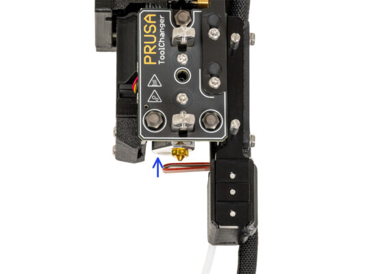
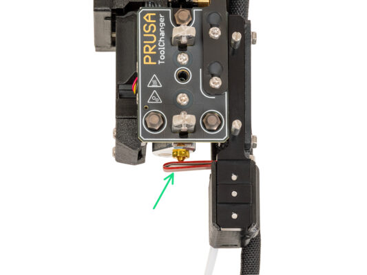
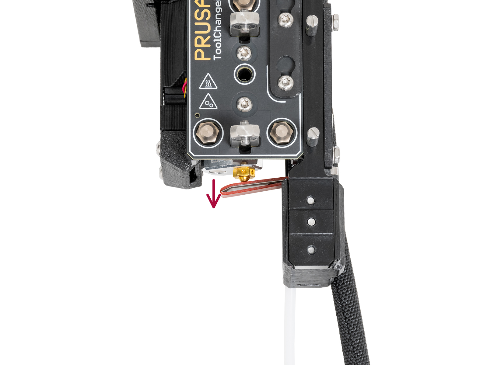
Insert the semi-transparent PTFE tube into the FESTO fitting on the Nextruder. Push it all the way in.

Assemble and connect all Nextruders.
Good job!
Nozzle seal height calibration
On the Nozzle seal heigh calibration steps we used docked Nextruder without the printer for better visibility, proceed next steps on your printer. Do not dismantle the docks.
In the next step, we'll calibrate the height of the nozzle seal.
Using the 2.5 mm Allen key, tighten or untighten the M3x30 screw to calibrate the height of the nozzle seal.
If you have an older version of the XL-dock-cable-router, follow the instructions for the new XL-dock-cable-router.
Proceed to the next step.
Nozzle seal height calibration
If is the Nozzle seal too low or too high, we need to reposition its height.
Using a 2.5 mm Allen key:
Turn the M3x30 screw clockwise to set the Nozzle seal lower.
Turn the M3x30 screw counterclockwise to set the Nozzle seal higher.
The correct position of the nozzle seal is when it isn't bent and is touching the nozzle.
Haribo time!
Haribo time!
Eat another eight gummy bears.
Did you know that the bright colors of gummy bears are achieved through the use of food coloring, which adds to their visual appeal.
Remaining fasteners
Remaining fasteners
To avoid the concern of having leftover nuts and screws, refer to the following list of fasteners that should remain unused from the initial package upon completing the assembly.
Note that if you have used any spare, the final count may vary.

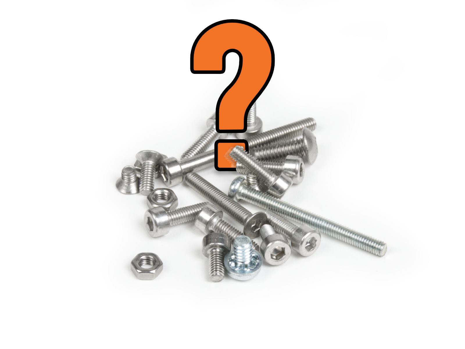
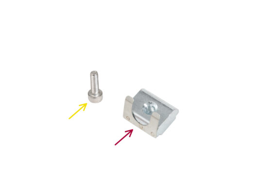
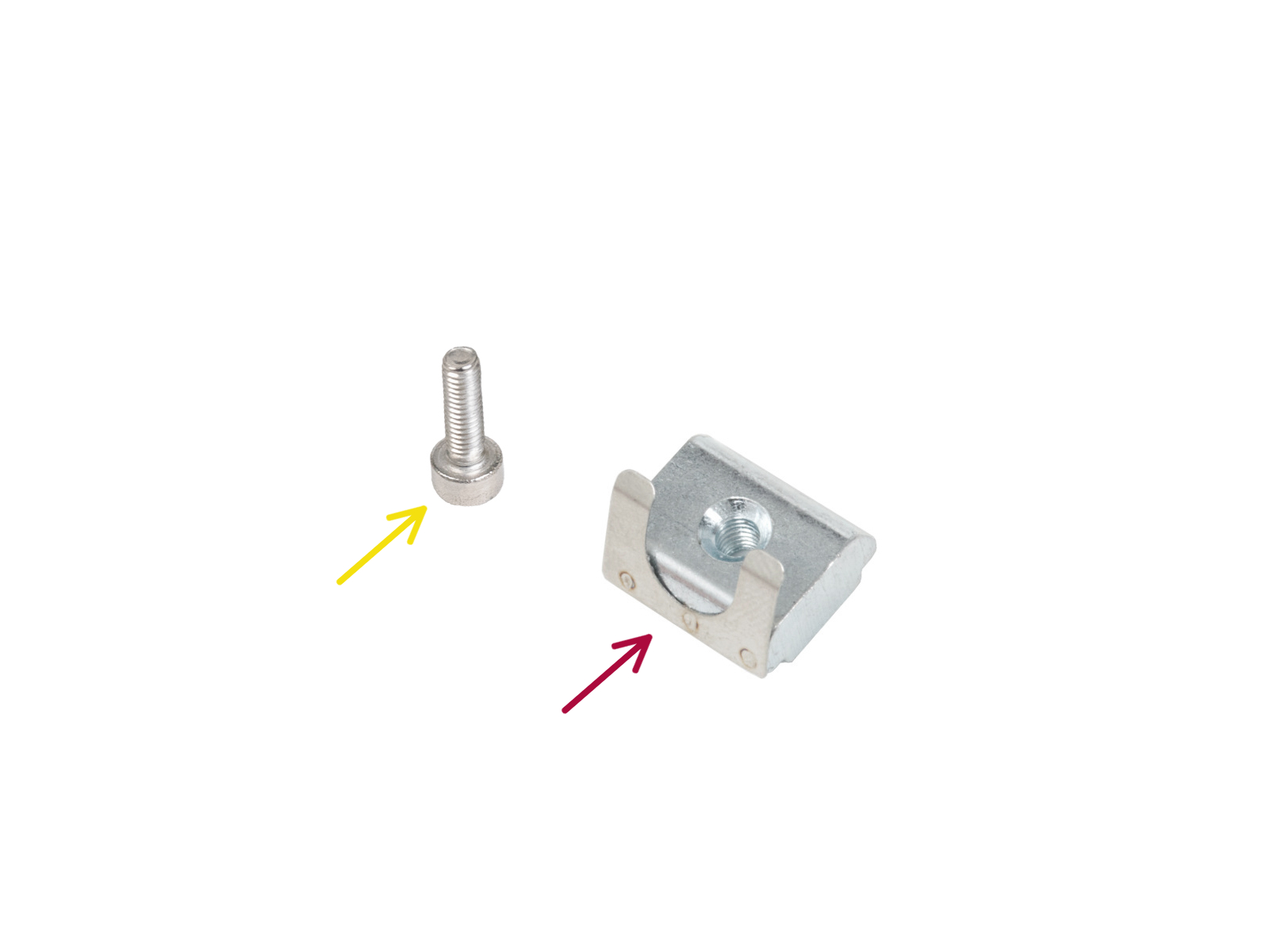
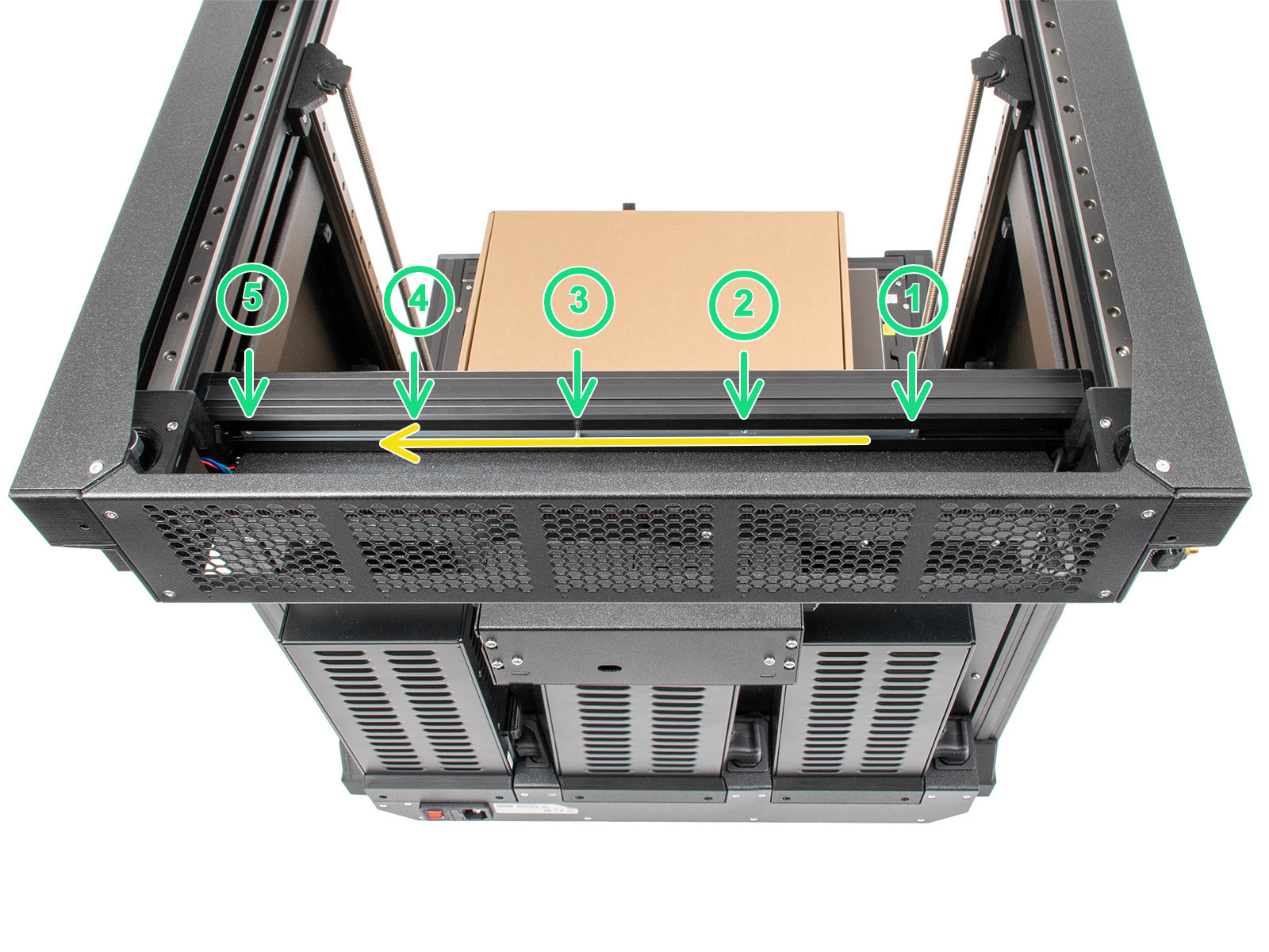
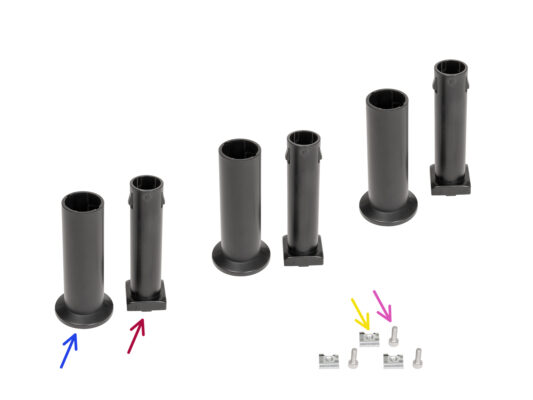
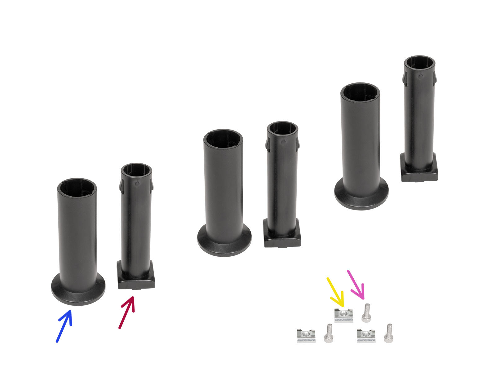
Remaining fastener items:
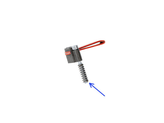
- Terminal screw (1x)
- M3x6 (1x) 
-
M3x8 (1x) 
M3x10 (2x) 
- M3x12 (1x)
- M3x20rT (2x)
- M4x12 (1x)

Almost done!
Almost done!
Congratulation! Your Original Prusa XL is ready to be fired up!
Compare the final look with the picture.
Now, let's go to the last chapter 6. First run.
Was this guide helpful?

Comments

Still have questions?

Still have questions?

If you have a question about something that isn't covered here, check out our additional resources.
And if that doesn't do the trick, you can send an inquiry to [email protected] or through the button below.

Contact us