Français
Login
Imprimantes 3D
Matériaux
Pièces & accessoires
Logiciel
Modèles 3D
Applications
Communauté
Aide
Academy
Blog
Entreprise
Support
Original Prusa i3 MK2S
Assemblage du kit Original Prusa i3 MK2S
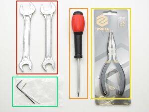
2. Y-axis assembly | Get the necessary tools
1. Get the necessary tools
Step 1 of 45 (Chapter 2 of 9)
Contenu
Commentaires
⬢
13/17mm spanners
⬢
3.6mm flathead screwdriver
⬢
Needle-nose pliers
⬢
2.5 and 1.5mm Allen key
Loading...
Suivant
Contenu
Assemblage du kit Original Prusa i3 MK2S
1.Introduction
2. Y-axis assembly [Traduction en cours]
Get the necessary tools
3D printed parts
Assemble the Y-axis rods
Assemble the Y-axis stage rear
Assemble the Y-axis stage front
Fully assemble the Y-axis stage
Preparing for Y-axis stage
Tighten the sides to the y-axis stage
VIDEO for step 8
Identifying the length of rods
Adjust the length of the Y-axis stage
VIDEO for step 11
Marker identification
Correct bearing orientation
Assemble the Y-carriage
Tighten Y-carriage u-shaped bolts
Assembly of the Y-idler
Tighten the Y-idler
Y-motor-distance assembly
Y-axis motor
Adding the Y-axis endstop
Tightening the Y-axis endstop
Y-axis endstop cable guide
Assemble the Y-belt holder
Assemble the Y-carriage rods
Assemble the Y-axis stage
Tighten the zipties on the Y-axis stage
Assemble the belt on the Y-axis, part 1
Assemble the belt on the Y-axis, part 2
Loosening the motor
Assemble the Y-motor pulley
The Y-axis belt placement
Tighten the Y-axis belt, part 1
Tighten the Y-axis belt, part 2
Tensioning the belt
Video for steps 29-35
Adjust the Y-idler
Adjust the Y-motor-mount part
Tighten the screws in the pulley
The Y-axis stage cable management
Levelling the Y-axis
Secure the axis feet
The Y-Endstop check
Double check the Y-carriage!
All done!
3. Assemblage de l’axe X
4. Assemblage de l’axe Z
5. Assemblage de l'Extrudeur
6. Assemblage du LCD
7. Assemblage de l'alimentation et du lit chauffant
8. Assemblage de l'électronique
9. Contrôle avant lancement
Commentaires
Se connecter
pour poster un commentaire
Aucun commentaire