- English
- Italiano
- Deutsch
- Polski
- Français
- Home
- Troubleshooting [進行中の翻訳]
- プリンタートラブルシューティング
- Status LED explained (MMU3)
Status LED explained (MMU3)
- プリント品質のトラブルシューティング
- プリンタートラブルシューティング
- A64 Overheat #10207 (SL1/SL1S)
- 周囲温度のチェック(MK3/MK3S)
- Ambient temperature too cold #10703 (SL1/SL1S)
- Ambient temperature too high #10702 (SL1/SL1S)
- An unexpected error has occurred #10701 (SL1)
- Another action is already running #10506 (SL1/SL1S)
- BBFの割当に失敗しました #13531 (MK4) #21531 (MK3.9)
- BBF Allocation Failed #17531 (XL)
- BBFの初期化に失敗しました #13532 (MK4) #21532 (MK3.9)
- BBF Initialization failed #17532 (XL)
- ヒートベッド最高温度エラー #13205 (MK4) #21205 (MK3.9)
- ヒートベッド最低温度エラー #13207 (MK4) #21207 (MK3.9)
- ベッドプリヒートエラー #13201 (MK4) #21201 (MK3.9)
- ヒートベッドの熱暴走 #13203 (MK4) #21203 (MK3.9)
- 飛んだフューズ (MINI)
- Blown Fuse (MK2S/MK2.5/MK2.5S)
- 飛んだヒューズ (MK3/MK3S/MK3S+)
- 飛んだヒューズ (MK4)
- Boost board problem #10320 (SL1S)
- Bricked printer (SL1/SL1S)
- Calibration project is invalid #10543 (SL1/SL1S)
- Can't copy project #10704 (SL1/SL1S)
- Cannot get update channel #10514 (SL1)
- Cannot read project #10539 (SL1/SL1S)
- Cannot remove project #10545 (SL1/SL1S)
- ホットエンドの詰まり (MK4)
- Clogged hotend (XL)
- ノズル/ホットエンドの詰まり (MINI/MINI+)
- ノズル/ホットエンドの詰まり (MK3S, MK2.5S)
- Connect Registration Failed
- Connect Registration Failed #12401 (MINI)
- Connect Registration Failed #13401 (MK4)
- Connect Registration Failed #17401 (XL)
- Connect Registration Failed #21401 (MK3.9)
- Connect Registration Failed #23401 (MK3.5)
- Directory not empty #10546 (SL1/SL1S)
- Disconnected UV LED panel #10321 (SL1/SL1S)
- Display test failed #10120 (SL1/SL1S)
- Dwarf error #17502 (XL)
- Dwarf error #17503 (XL)
- EEPROM I2C 受信ビジー #13316 (MK4) #21316 (MK3.9)
- EEPROM I2C Receive Busy #17316 (XL)
- Emergency stop #12510 (MINI)
- 緊急停止 #13510 (MK4) #21510 (MK3.9)
- Emergency stop #17510 (XL)
- ESPエラー #13504 (MK4) #21504 (MK3.9)
- ESPエラー #13505 (MK4) #21505 (MK3.9)
- ESPエラー #13506 (MK4) #21506 (MK3.9)
- ESP error #17504 (XL)
- ESP error #17505 (XL)
- ESP error #17506 (XL)
- Expect overheating #10714 (SL1/SL1S)
- External SPI flash W25X20CL/xFLASH が反応しない - エラー
- エクストルーダーのブロブ
- Extruder Maxtemp error #17206 (XL)
- Extruder Mintemp error #17208 (XL)
- エクストルーダーのノイズ
- Extruder preheat error #17202 (XL)
- Extruder temp not matching #17210 (XL)
- Extruder thermal runaway #17204 (XL)
- プリント途中でエクストルーダーの押し出しが止まる現象(ヒートクリープ)
- ファクトリーリセット (MINI)
- ファクトリーリセット (MK2S/MK2.5S/MK3S)
- 工場出荷時の状態へのリセット (MK4/XL)
- Factory Reset (MMU)
- Factory reset (MMU2S pre firmware 1.0.6)
- Factory reset (SL1/SL1S)
- Failed to read the configuration file #10505 (SL1)
- Zキャリブレーションの失敗 (MK3S/MK2.5S)
- Fan failure #10106 (SL1/SL1S)
- Fan warning #10713 (SL1/SL1S)
- フィラメントのアンロード失敗(MINI/MINI+)
- フィラメントがロードされていかない
- フィラメントがロードされない (MK4)
- Filament not loading (XL)
- フィラメントセンサー (MK4, MK3.9)
- File already exists! #10520 (SL1)
- File not found #10518 (SL1/SL1S)
- File system error #12613 (MINI/MINI+)
- ファイルシステムエラー #13613 (MK4) #21613 (MK3.9)
- FINDA setup and troubleshooting
- FINDA: Filament Stuck #04102 (MMU)
- Firmware in the internal flash corrupted! #12608 (MINI)
- Firmware missing #17612 (XL)
- Firmware Update Required #13701 (MK4) #21701 (MK3.9) #23701 (MK3.5)
- ファームウェアのアップデート時の問題 (MK2S/MK3S/MMU2S)
- First layer does not stick (SL1/SL1S)
- Flash erase error #12605 (MINI/MINI+)
- フラッシュ消去エラー #13605 (MK4) #21605 (MK3.9)
- Flash erase error #17605 (XL)
- 内蔵メモリ内のFWが破損しています #13608 (MK4) #21608 (MK3.9)
- FW in internal flash corrupted #17608 (XL)
- Hash verification failed #12607 (MINI/MINI+)
- ハッシュの検証に失敗 #13607 (MK4) #21607 (MK3.9)
- Hash verification failed #17607 (XL)
- ヒートベッドが正常に加熱されない
- ヒートベッドポートの過電流 #13309 (MK4) #21309 (MK3.9)
- ヒートブレイク最高温度エラー #13212 (MK4) #21212 (MK3.9)
- Heatbreak Maxtemp error #17212 (XL)
- ヒートブレイク最低温度エラー #13211 (MK4) #21211 (MK3.9)
- Heatbreak Mintemp error #17211 (XL)
- Homing Error #12301 (MINI)
- X軸ホーミングエラー #13304 (MK4) #21304 (MK3.9)
- Homing error X #17304 (XL)
- Y軸ホーミングエラー #13305 (MK4) #21305 (MK3.9)
- Homing error Y #17305 (XL)
- Z軸ホーミングエラー #13301 (MK4) Z #21301 (MK3.9)
- Homing error Z #17301 (XL)
- Homing Error Z #23301 (MK3.5)
- ホットエンドファンが回転しない
- Hotend maxtemp error #23206 (MK3.5)
- ホットエンド最低温度エラー #13208 (MK4) #21208 (MK3.9)
- Hotend mintemp error #23208 (MK3.5)
- ホットエンドプリヒートエラー #13202 (MK4) #21202 (MK3.9)
- Hotend preheat error #23202 (MK3.5)
- Hotend temp not matching #23210 (MK3.5)
- ホットエンドの熱暴走 #13204 (MK4) #21204 (MK3.9)
- Hotend thermal runaway #23204 (MK3.5)
- I2C受信の失敗 #13315(MK4) #21315 (MK3.9)
- I2C Receive failed #17315 (XL)
- I2C受信のタイムアウト #13317 (MK4) #21317 (MK3.9)
- I2C Receive Timeout #17317 (XL)
- I2C受信の未定義 #13318 (MK4) #21318 (MK3.9)
- I2C Receive undefined #17318 (XL)
- I2C 送信ビジー #13312 (MK4) #21312 (MK3.9)
- I2C Send Busy #17312 (XL)
- I2C送信の失敗 #13311(MK4) #21311 (MK3.9)
- I2C Send Failed #17311 (XL)
- I2C送信のタイムアウト #13313(MK4) #21313 (MK3.9)
- I2C Send Timeout #17313 (XL)
- I2C送信の未定義 #13314 (MK4) #21314 (MK3.9)
- I2C Send Undefined #17314 (XL)
- Imposter! Fake signature #17606 (XL)
- Incorrect printer model #10705 (SL1/SL1S)
- Internal memory full #10516 (SL1/SL1S)
- Invalid API key #10405 (SL1/SL1S)
- Invalid FW size on USB #12603 (MINI/MINI+)
- USBのFWサイズが無効 #13603 (MK4) #21603 (MK3.9)
- Invalid FW size on USB flash drive #17603 (XL)
- IR filament sensor calibration (MMU2S)
- IRフィラメントセンサーのトラブルシューティング(MINI/MINI+)
- IRフィラメントセンサーのトラブルシューティング(MK2.5S, MK3S)
- LCDスクリーンが機能しない
- LEDメモリーエラー #13529 (MK4) #21529 (MK3.9)
- LED Memory Error #17529 (XL)
- Live Z adjust not saving
- Load to extruder failed #04108 (MMU)
- ロードセルのキャリブレーション不良 #13527 (MK4) #21527 (MK3.9)
- Loadcell Bad Configuration #17527 (XL)
- ロードセル測定の失敗 #13526 (MK4) #21526 (MK3.9)
- Loadcell measure failed #17526 (XL)
- ロードセル未キャリブレーション #13523 (MK4) #21523 (MK3.9)
- Loadcell not calibrated #17523 (XL)
- Loadcell Tare Error #13524 (MK4) #21524 (MK3.9)
- Loadcell tare error #17524 (XL)
- ロードセル基準値の設定失敗 #13525 (MK4) #21525 (MK3.9)
- Loadcell tare failed #17525 (XL)
- ロードセルのタイムアウト #13528(MK4) #21528 (MK3.9)
- Loadcell timeout #17528 (XL)
- Logging data over serial line (MMU2S)
- Loud noises from printer (SL1/SL1S)
- M.I.N.D.A./SuperPINDA センサーのテスト (MINI/MINI+)
- Marlin Request Timeout #13530 (MK4) #21530 (MK3.9) #23530 (MK3.5)
- Marlin Request Timeout #17530 (XL)
- Mask noavail warning #10709 (SL1/SL1S)
- ヒートベッドの温度エラー/Maxtemp error bed #12205 (MINI)
- ホットエンドの温度エラー/Maxtemp error print head #12208 (MINI)
- MCU Maxtemp Error #17213 (XL)
- ヒートベッドの温度エラー/Mintemp error bed #12207 (MINI)
- ホットエンドの温度エラー/Mintemp error print head #12208 (MINI)
- Misaligned PINDA Sensor (MK2/S)
- Missing parts (SL1/SL1S)
- MK3Sがフィラメント交換を促し続ける
- MMU MCU Underpower #04307 (MMU)
- MMU Overcurrent #13310 (MK4) #21310 (MK3.9) #23310 (MK3.5)
- MMU2S idler unable to move freely
- MMU2S LEDs meaning
- MMU2S Selector not moving
- Modular bed error #17250 (XL)
- Modular bed error #17251 (XL)
- Modular bed error #17252 (XL)
- Modular bed error #17253 (XL)
- Modular bed error #17254 (XL)
- Modular bed error #17255 (XL)
- Modular bed error #17256 (XL)
- Modular bed error #17257 (XL)
- Modular bed error #17302 (XL)
- Modular bed error #17303 (XL)
- Modular Bed Error #17319 (XL)
- Modular Bed Error #17320 (XL)
- Modular bed error #17501 (XL)
- Multimeter usage
- No file on USB #12604 (MINI/MINI+)
- No file to reprint #10508 (SL1)
- No FW in internal flash #12612 (MINI/MINI+)
- 内蔵フラッシュ内にFWが存在しない #13612 (MK4) #21612 (MK3.9)
- USBにファームウェアがありません #13604 (MK4) #21604 (MK3.9)
- No FW on USB flash drive #17604 (XL)
- Not connected to network #10402 (SL1/SL1S)
- Not enough layers #10540 (SL1/SL1S)
- Not enough resin #10706 (SL1/SL1S)
- Nozzle Cleaning Failed (XL)
- ノズルがヒートベッドに衝突する
- ノズルヒーターへの過電流 #13308 (MK4) #21308 (MK3.9)
- Nozzle Heater Overcurrent #23308 (MK3.5)
- Object cropped warning #10710 (SL1/SL1S)
- Opening project failed #10504 (SL1/SL1S)
- メモリー切れ #13507 (MK4) #21507 (MK4/MK3.9)
- Out of memory #17507 (XL)
- M.I.N.D.A./SuperPINDA センサーのテスト (MINI/MINI+)
- Parameters out of range #10707 (SL1/SL1S)
- Pin not reached #17107 (XL)
- PNGバッファのメモリ不足 #13508 (MK4) #21508 (MK3.9)
- PNG Buffer Full #17508 (XL)
- ベッドのプリヒートエラー #12201 (MINI)
- ホットエンドのプリヒートエラー/Preheat error print head #12202 (MINI)
- Preload failed #10503 (SL1/SL1S)
- Print examples missing #10523 (SL1/SL1S)
- プリントファンが回転していません
- プリンタの電源が入らない、または電源が切れたままになる
- Project analysis failed #10542 (SL1/SL1S)
- Project is corrupted #10541 (SL1/SL1S)
- PrusaLinkのトラブルシューティング
- Puppy error #17511 (XL)
- Puppy error #17512 (XL)
- Puppy error #17513 (XL)
- Puppy error #17514 (XL)
- Puppy error #17515 (XL)
- Puppy error #17516 (XL)
- Puppy error #17517 (XL)
- Puppy error #17518 (XL)
- Puppy error #17519 (XL)
- Puppy error #17520 (XL)
- Puppy error #17521 (XL)
- Puppy error #17522 (XL)
- Remote API error #10407 (SL1/SL1S)
- Resin low #10712 (SL1/SL1S)
- Resin measuring failed #10124 (SL1/SL1S)
- Resin sensor error #10307 (SL1/SL1S)
- Resin too high #10109 (SL1/SL1S)
- Resin too low #10108 (SL1/SL1S)
- Sample G-codes
- Saving log file (SL1/SL1S)
- SDカードが読めません
- SDカード・USBメモリ
- Selftest failed (XL)
- Signature verification failed #12606 (MINI/MINI+)
- 署名の検証に失敗 #13606 (MK4) #21606 (MK3.9)
- SL1 Tilt-mechanism error
- スパゲッティモンスター
- MINIを正確に調整する
- ステータスLEDについて (MK4/XL)
- Status LED explained (MMU3)
- During the regular MMU operation:
- MMU Firmware start:
- Other LED lights on the unit:
- Stuck filament detection #13101 (MK4) #21101 (MK3.9)
- Tangled filament
- Temp not matching heatbed #12209 (MINI/MINI+)
- Temp not matching print head #12210 (MINI/MINI+)
- Temperature out of range #10208 (SL1/SL1S)
- Thermal runaway(ヒートベッド) #12203 (MINI)
- Thermal runaway(プリントヘッド) #12204 (MINI)
- TMC driver shorted #04304 (MMU)
- TMC driver shorted #04314 (MMU)
- TMC driver shorted #04324 (MMU)
- Tool offset out of bounds #17104 (XL)
- Toolchanger error #17101 (XL)
- Tower check failed #10118 (SL1/SL1S)
- Unauthorized #10406 (SL1/SL1S)
- Unexpected error #10501 (SL1/SL1S)
- Unexpected MC error #10306 (SL1/SL1S)
- Unknown printer model #10323 (SL1/SL1S)
- Unsupported BBF version #12614 (MINI/MINI+)
- サポートされていないBBFバージョン #13614 (MK4) #21614 (MK3.9)
- Unsupported Buddy FW #17611 (XL)
- Unsupported firmware BBF file #17614 (XL)
- Unsupported printer model #17610 (XL)
- Unsupported printer type #12610 (MINI/MINI+)
- サポートされていないプリンタタイプ #13610 (MK4) #21610 (MK3.9)
- Unsupported printer version #12611 (MINI/MINI+)
- サポートされていないプリンタバージョン #13611 (MK4) #21611 (MK3.9)
- USBデバイスの過電流 #13307 (MK4) #21307 (MK3.9)
- USB Device Overcurrent #17307 (XL)
- USB drive not detected #10528 (SL1/SL1S)
- USB flash drive not connected #17602 (XL)
- USB flash error #17613 (XL)
- USB not connected #12602 (MINI/MINI+)
- USBメモリが接続されていなません #13602 (MK4) #21602 (MK3.9)
- USBポートの過電流 #13306 (MK4) #21306 (MK3.9)
- USB Port Overcurrent #17306 (XL)
- UV LED temperature error #10209 (SL1/SL1S)
- UV led voltage error #10309 (SL1)
- プリント中の振動とノイズ (MK3S+/MK2.5S)
- Wrong printer model #10544 (SL1/SL1S)
- Wrong revision of motion controller #10301 (SL1)
- XY position invalid #17106 (XL)
- XY probe unstable #17105 (XL)
- QR Error codes [進行中の翻訳]
- プリントエラーメッセージ
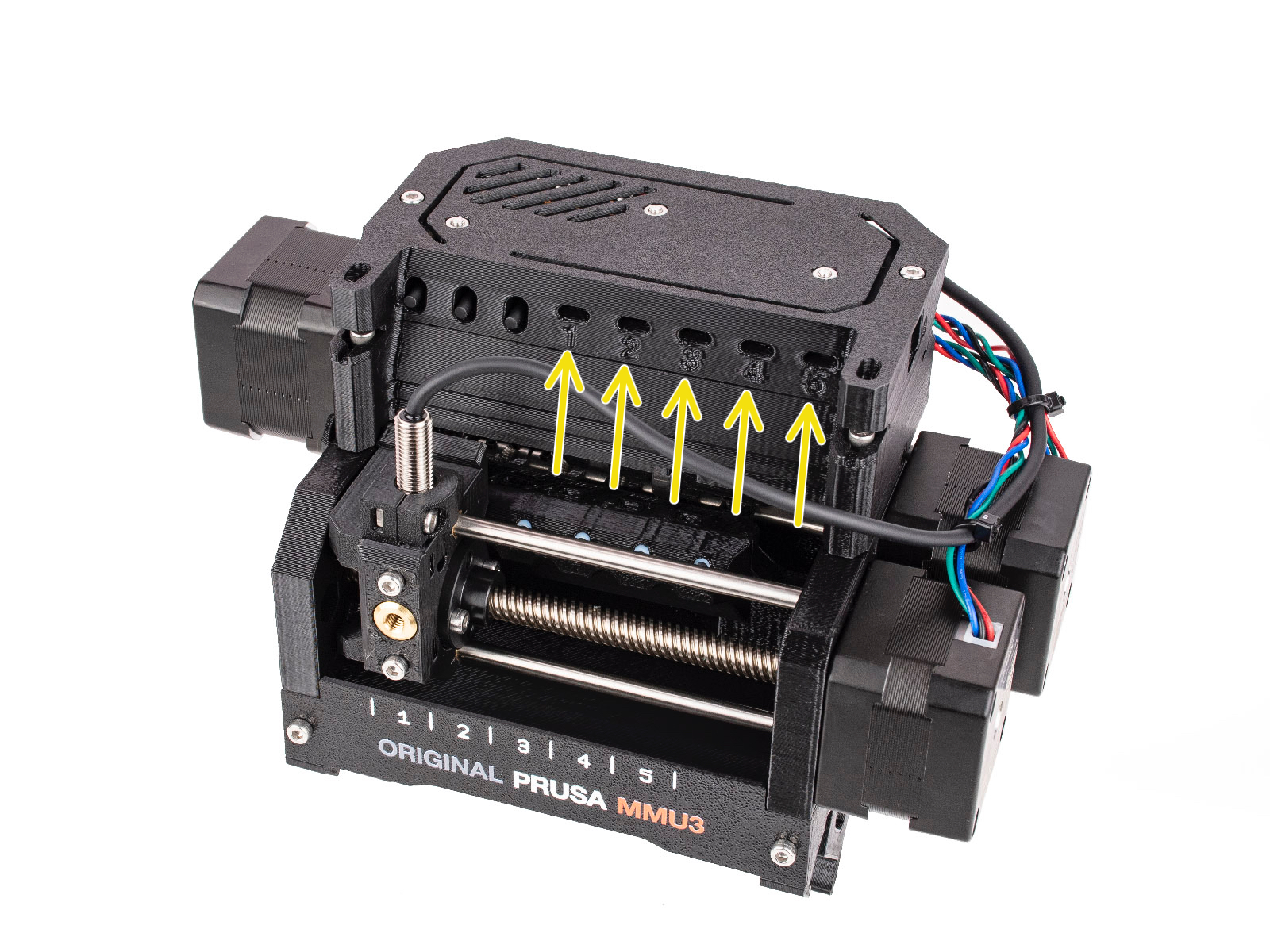
This article is describing the status of the LEDs located on the multi material unit. Together there are five LEDs on the unit that correspond to the five available filament positions.
Note that the earlier MMU2S firmware 1.0.6 or below behaves differently.
During the regular MMU operation:
- GREEN solid light: The MMU has a record of the given filament being loaded in the extruder.
- GREEN flashing light: There is a loading/unloading process going on.
- RED flashing light: There is a loading/unloading error with the given filament. The unit is waiting for user interaction.
- RED and GREEN flashing lights: Internal runtime error, refer to the error shown on the printer’s LCD.
MMU Firmware start:
After the MMU unit has been turned on or restarted, green LEDs light up from positions 5 to 1 shortly (~100ms). Each signalizes one component up and running:
- LED 5: Shift registers initialization
- LED 4: USART initialization
- LED 3: SPI communication initialization
- LED 2: motion system initialization
- LED 1: ADC initialization
If the MMU stops in this setup phase (the LEDs stay on and do not turn off), something is wrong with the electronics.
Then, a selftest routine is performed. It checks if the main control board behaves correctly and if all the signals from the microcontroller get to the TMC motor drivers on the control board properly. If the MMU unit suspects the communication with any of the three TMC motor drivers might not behave correctly, an error is shown. In that case, refer to the printer’s LCD screen.
LED lights indicate the ongoing phases of the selftest routine:
- LED 1: ok (green) / error (red) on STEP signal
- LED 2: ok (green) / error (red) on DIR signal
- LED 3: ok (green) / error (red) on ENABLE signal
- LED 4 indicates which TMC driver is being tested
- Idler = green
- Selector = red
- Pulley = green+red
- LED 5 is flashing green while the process is still ongoing.
Other LED lights on the unit:
There are also other less important LED indicators on the unit.
- A green LED on the MMU3 PD-board addon, on the back of the unit. It signalizes the board receiving power from the printer.
- An orange indicator "breathing" on the inside of the MMU unit, on the main control board, signalizes the electronics booting up.
- A red indicator on the top of the FINDA sensor signalizes the sensor being powered up and NOT detecting a filament.
Comments


Still have questions?
If you have a question about something that isn't covered here, check out our additional resources.
And if that doesn't do the trick, you can send an inquiry to [email protected] or through the button below.