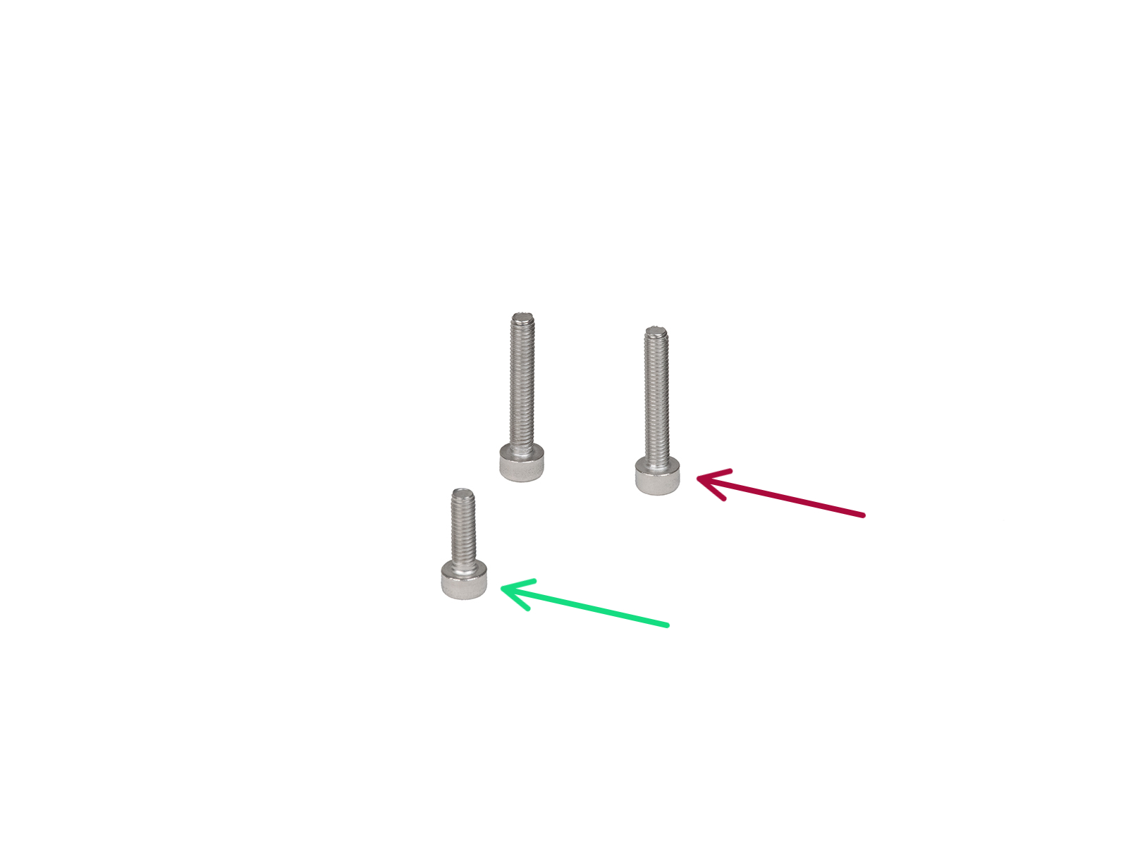
⬢For this chapter, please prepare:
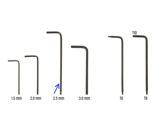
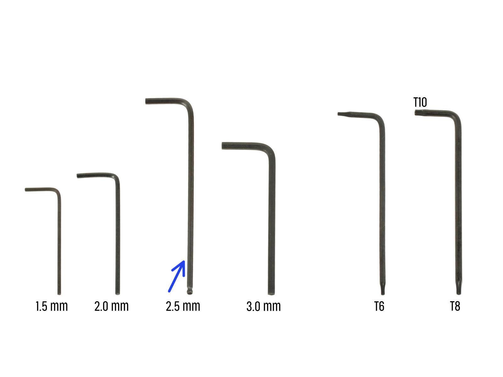
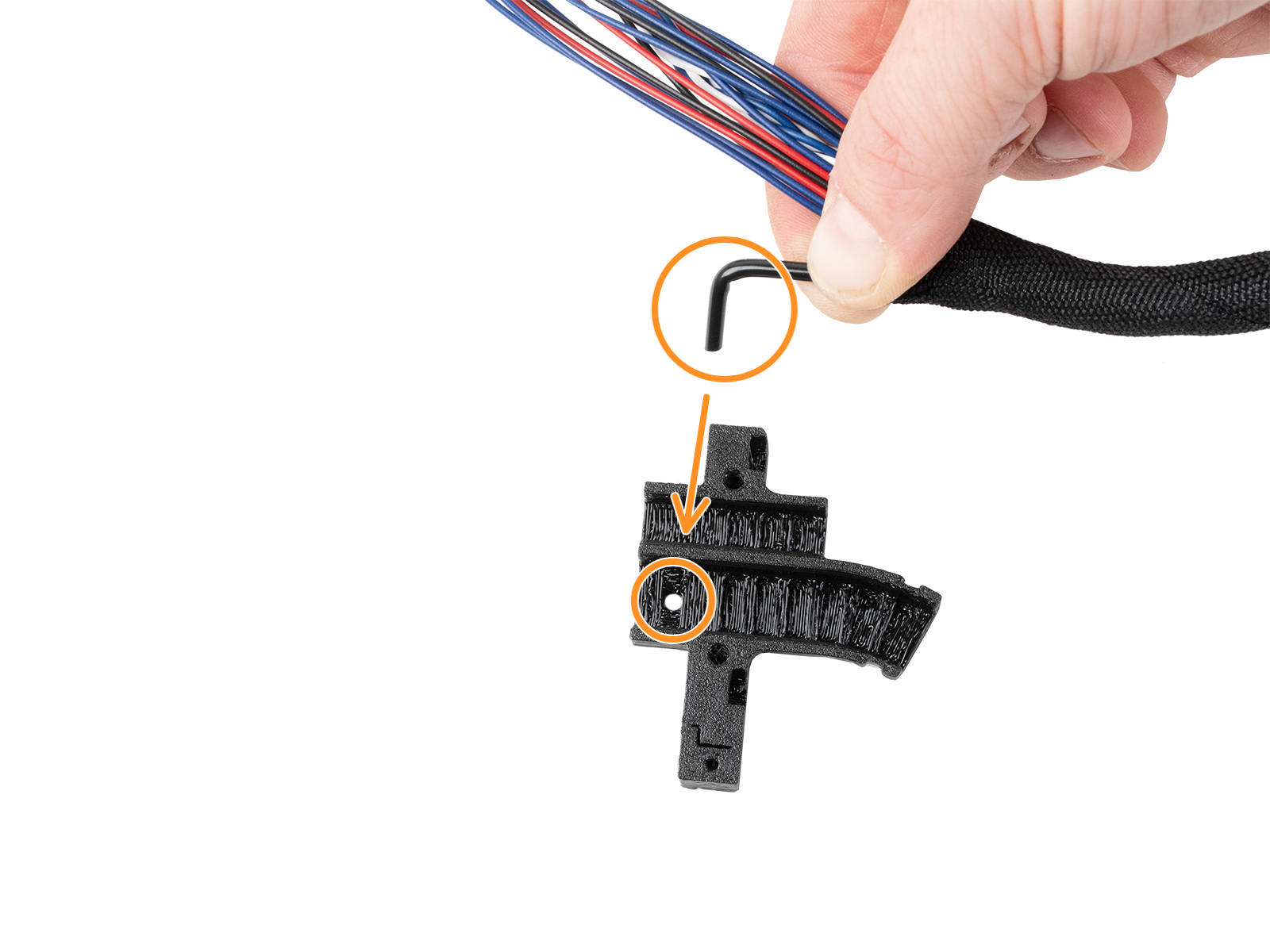
⬢2.5mm Allen key
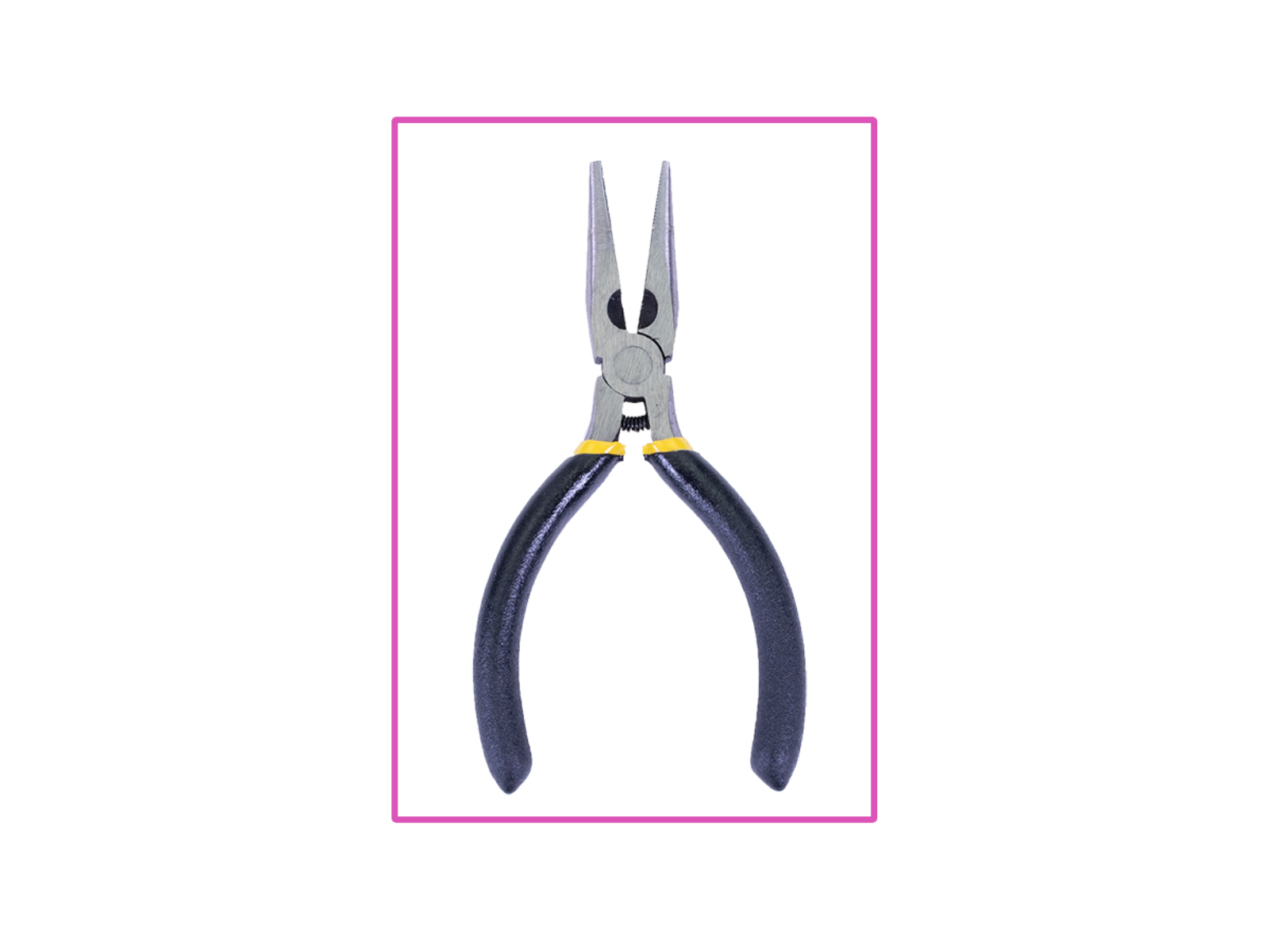
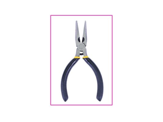
⬢Needle-nose pliers


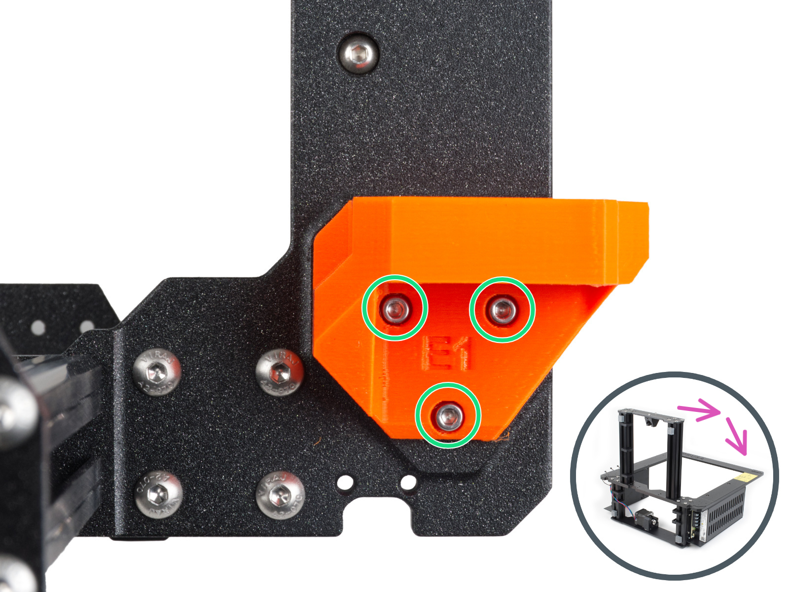
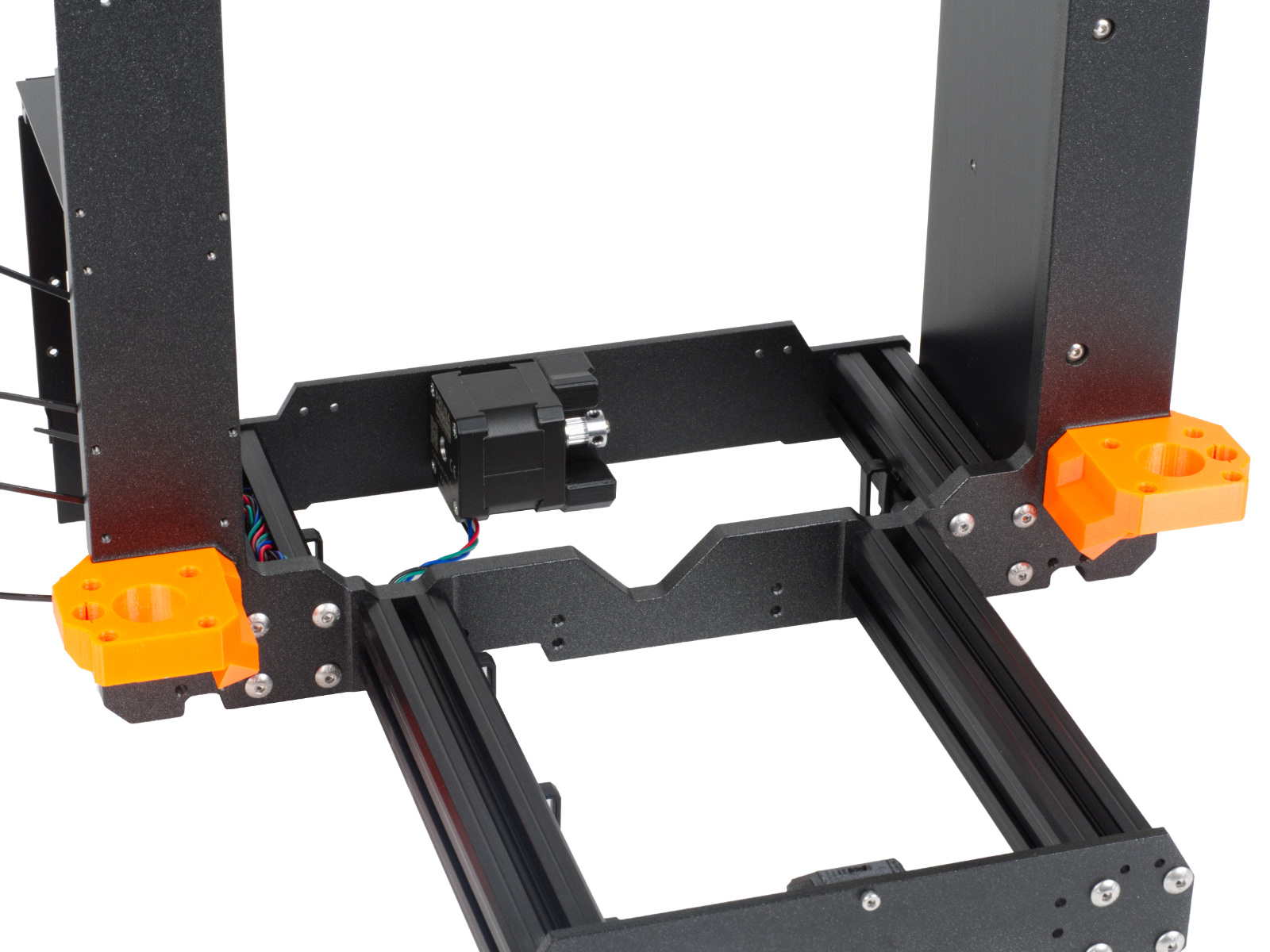


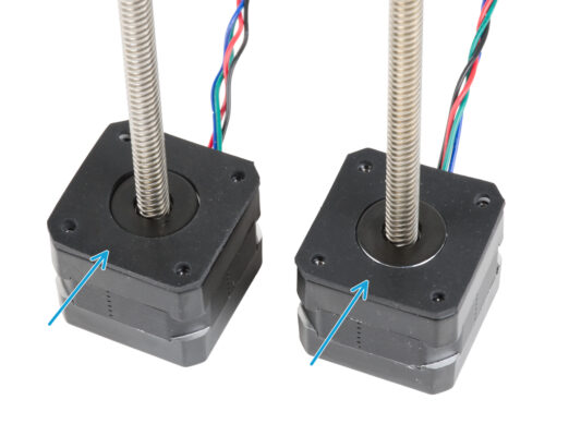
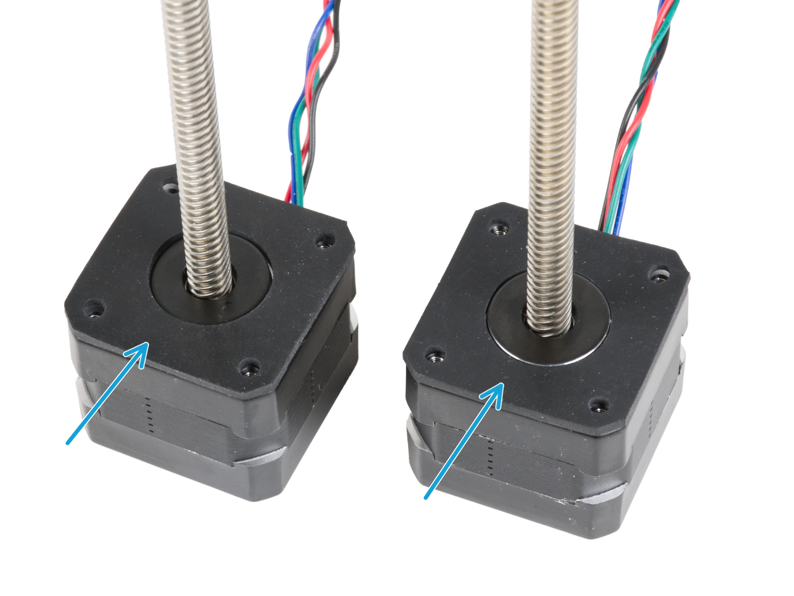

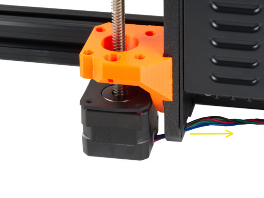
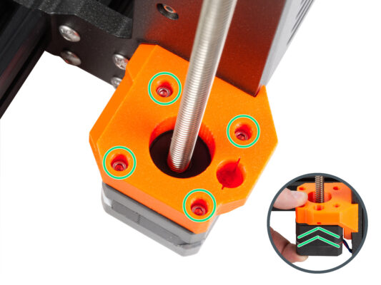

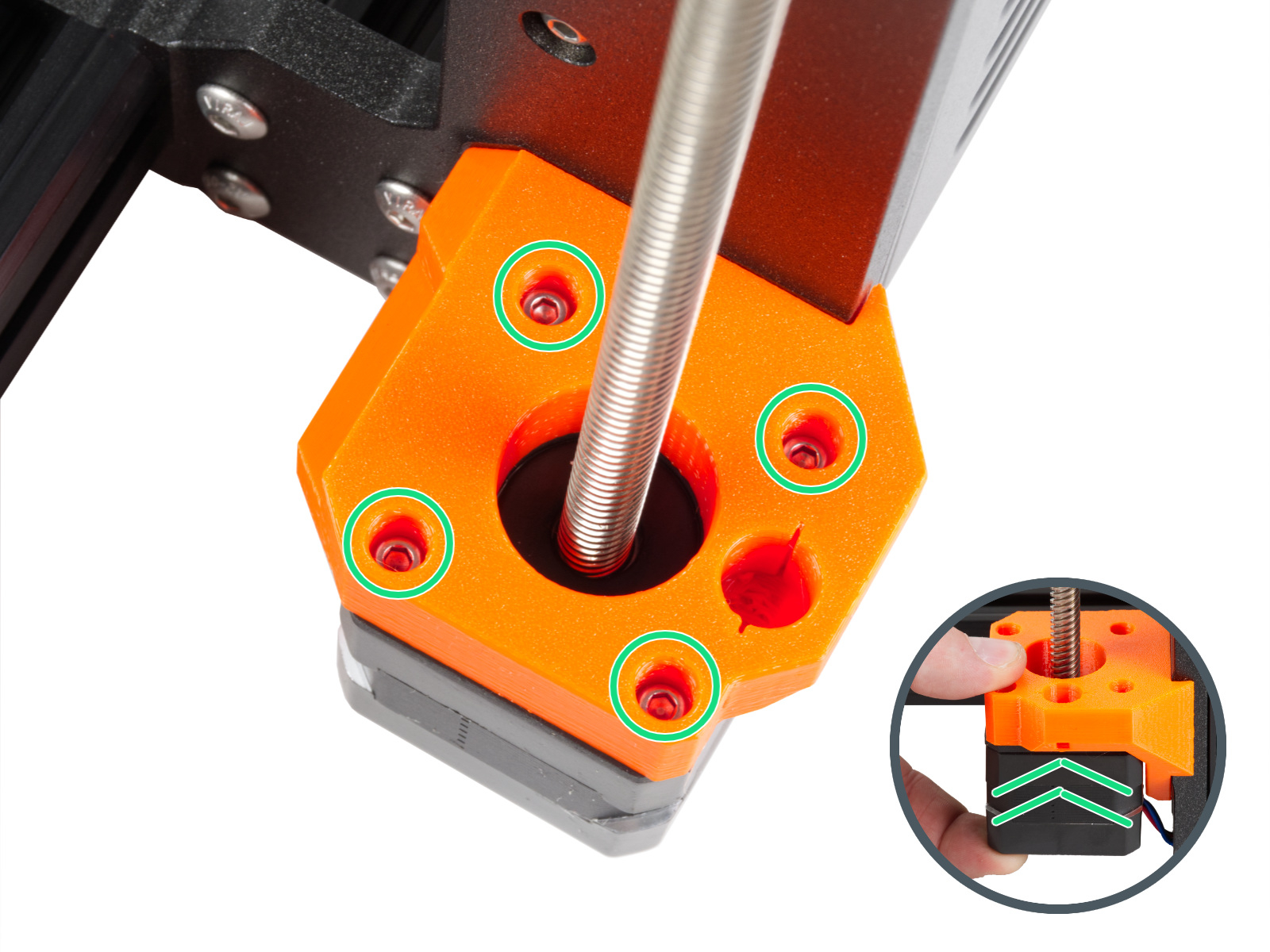


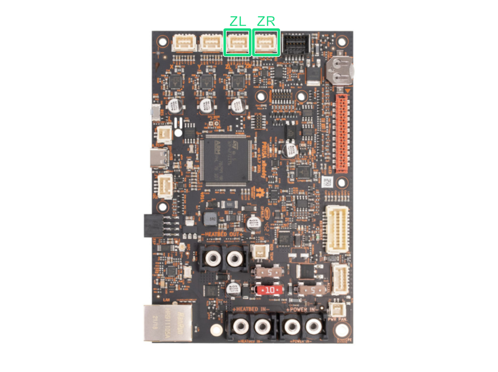
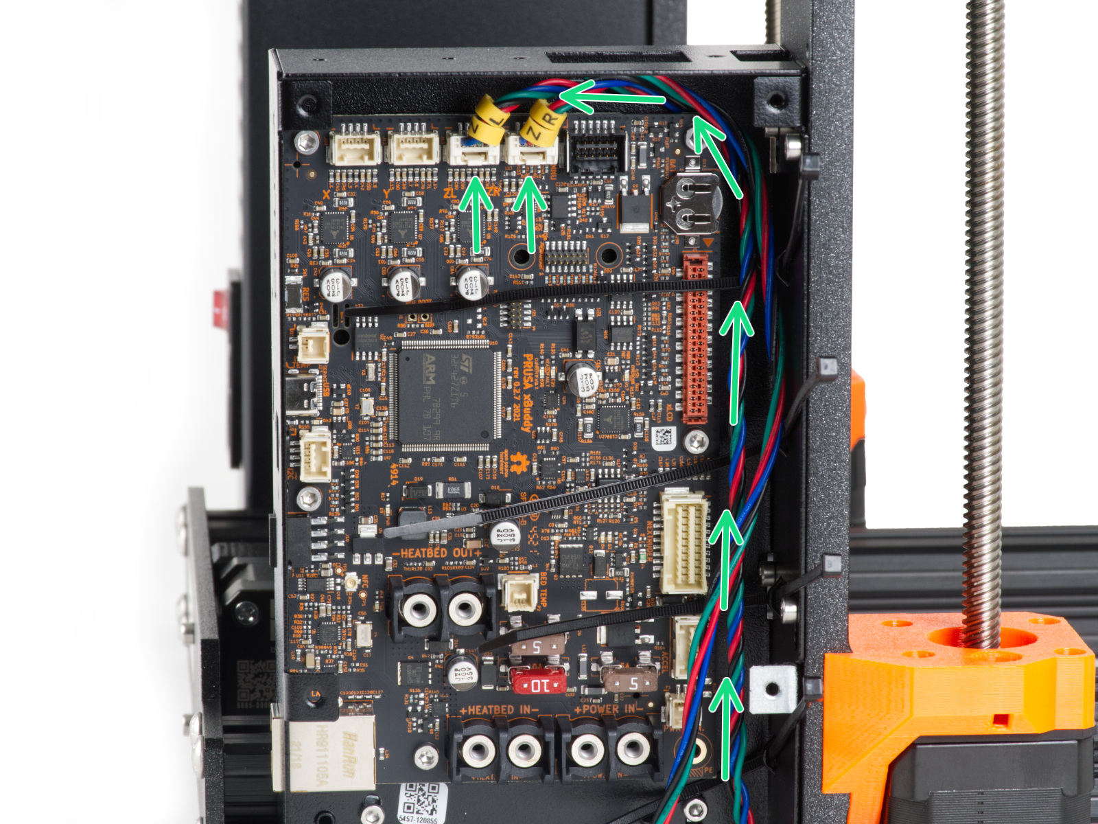
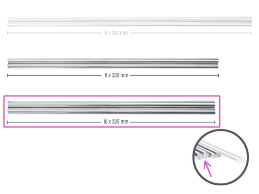

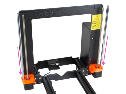

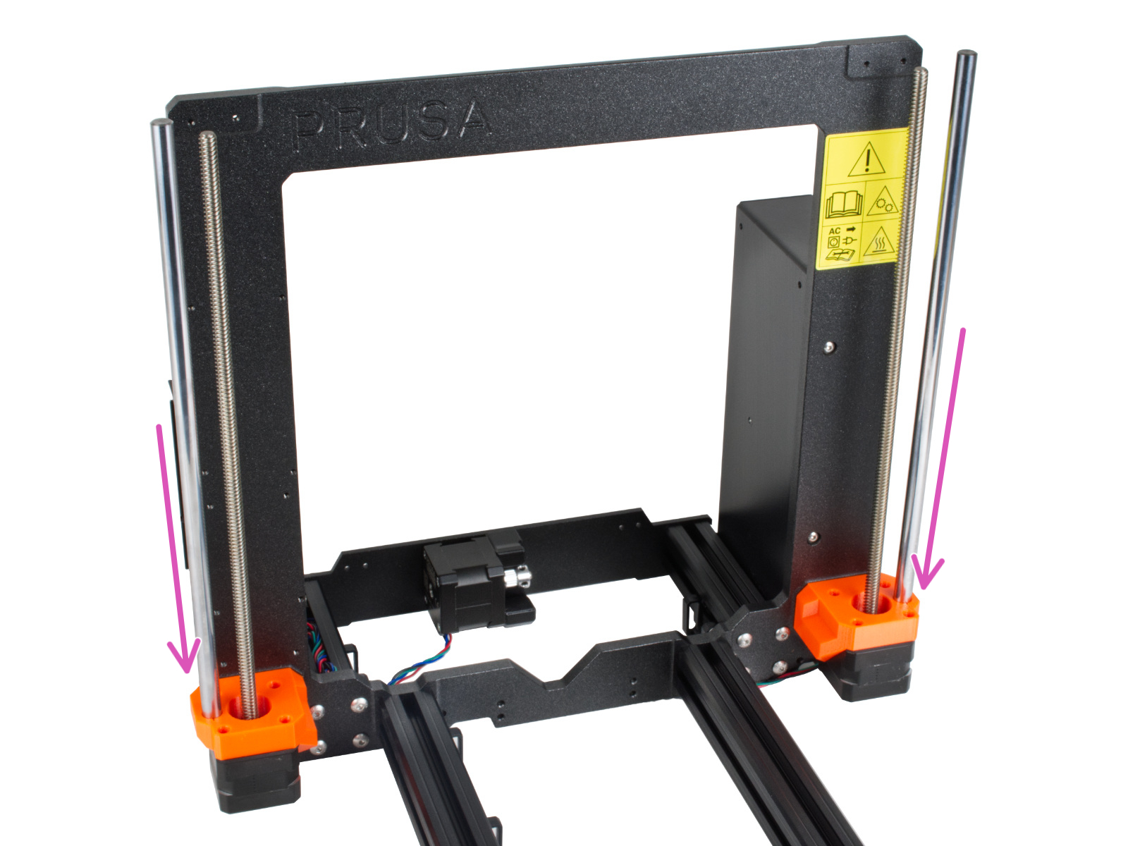
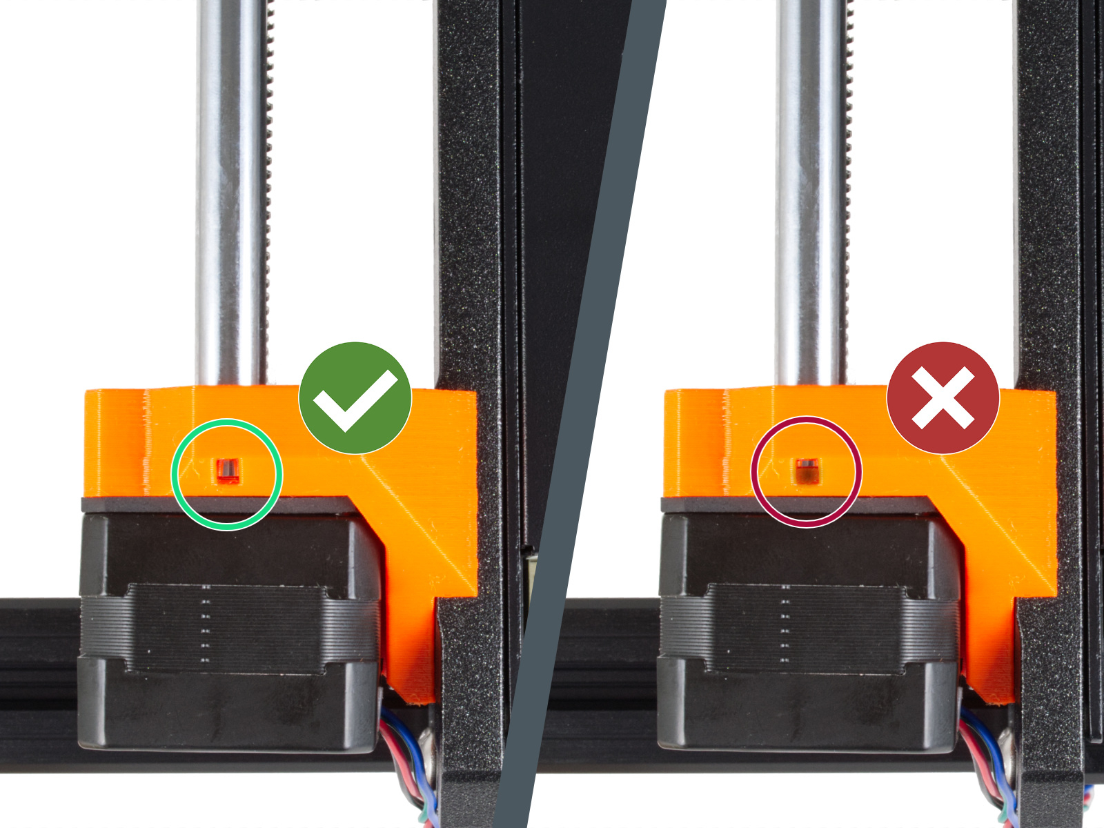


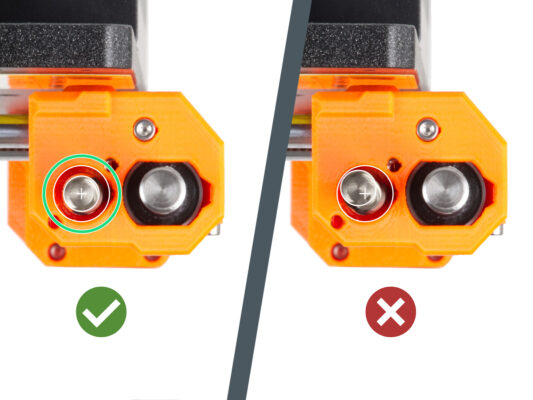
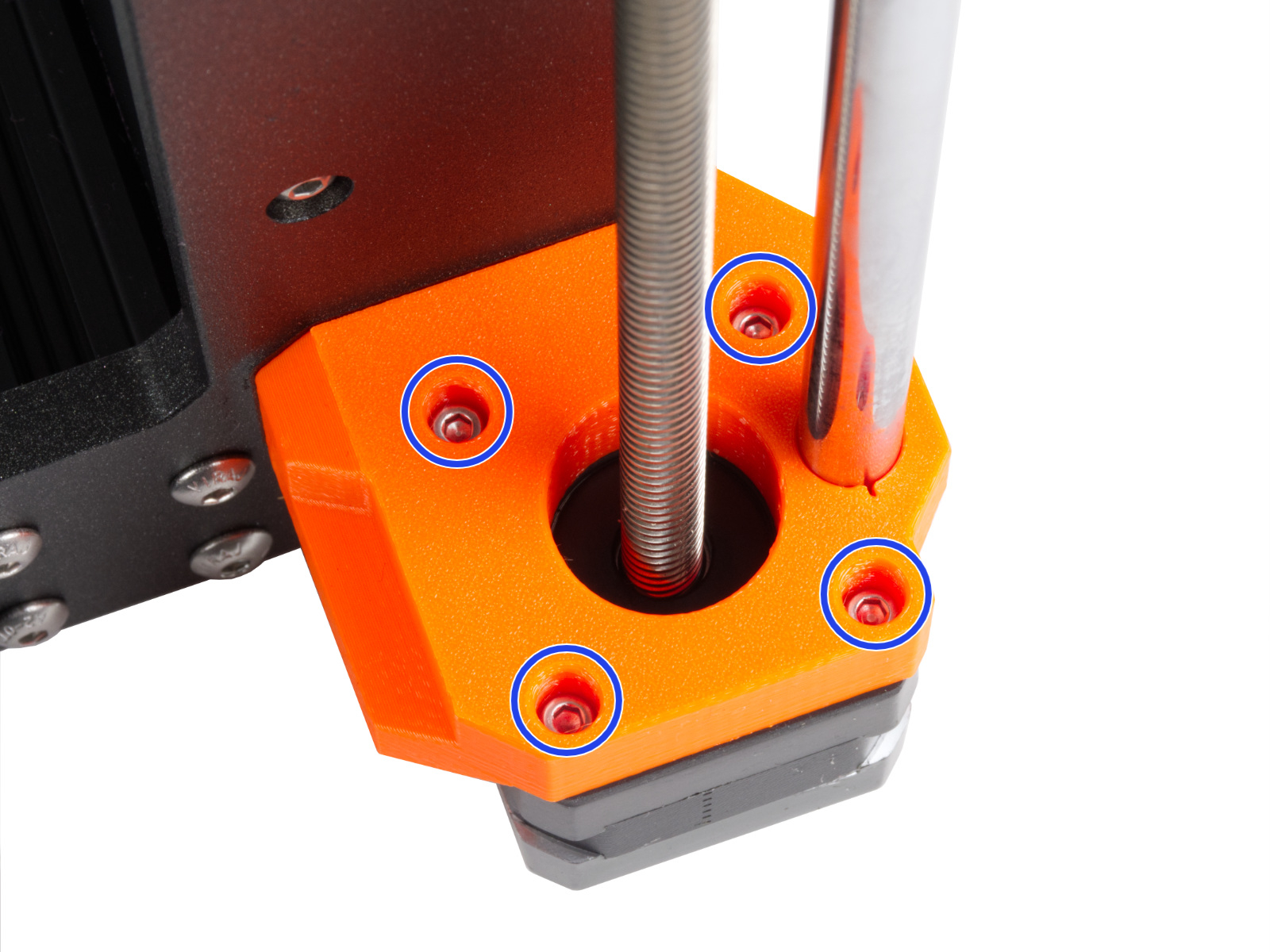
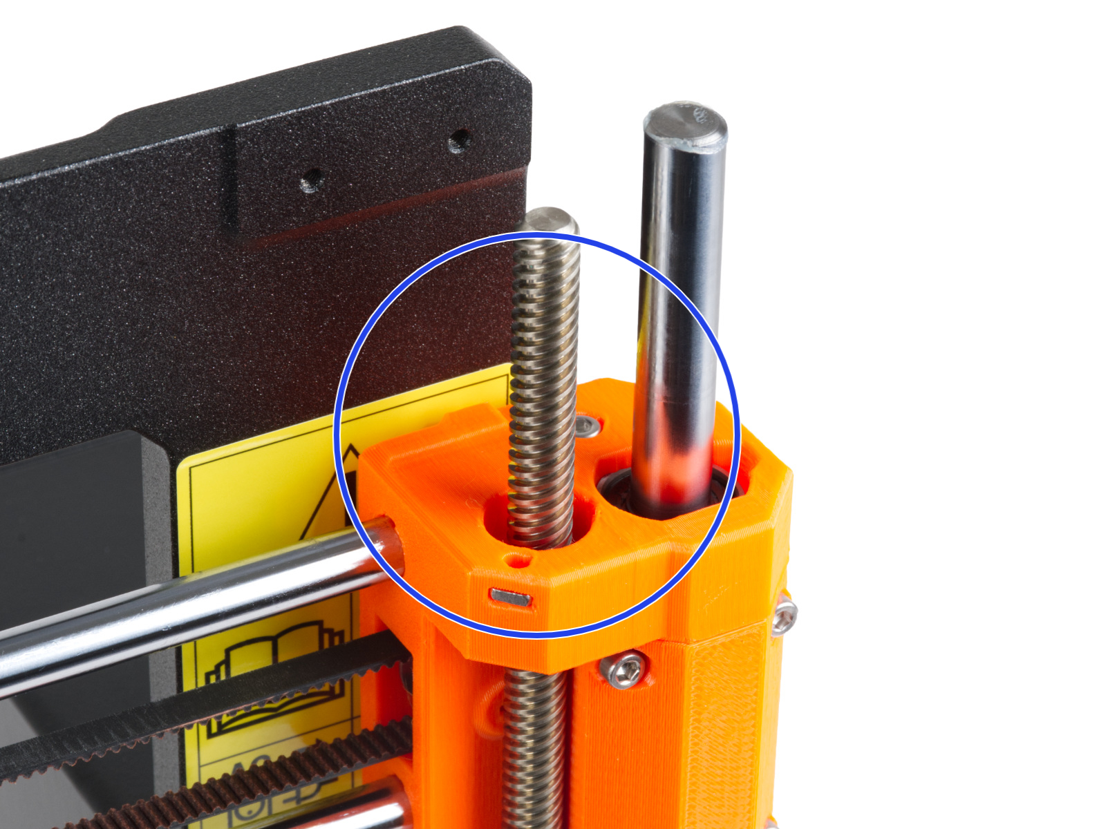
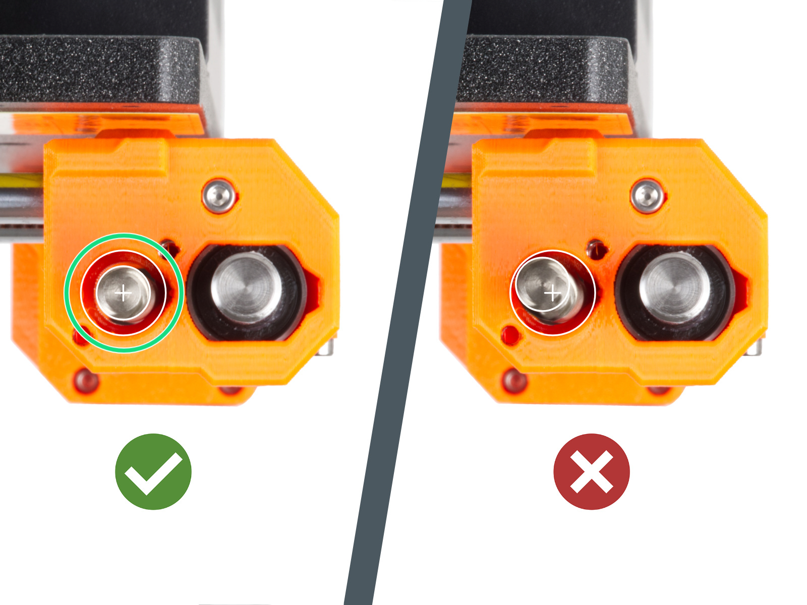
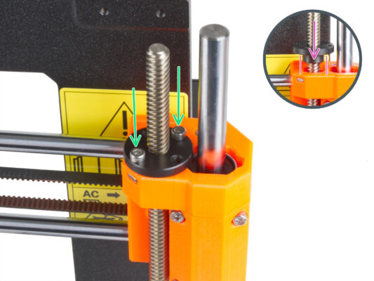
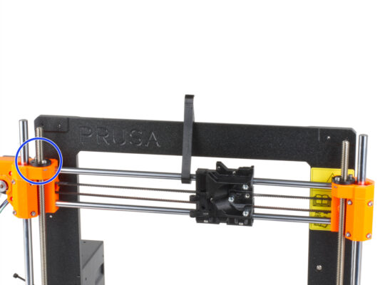
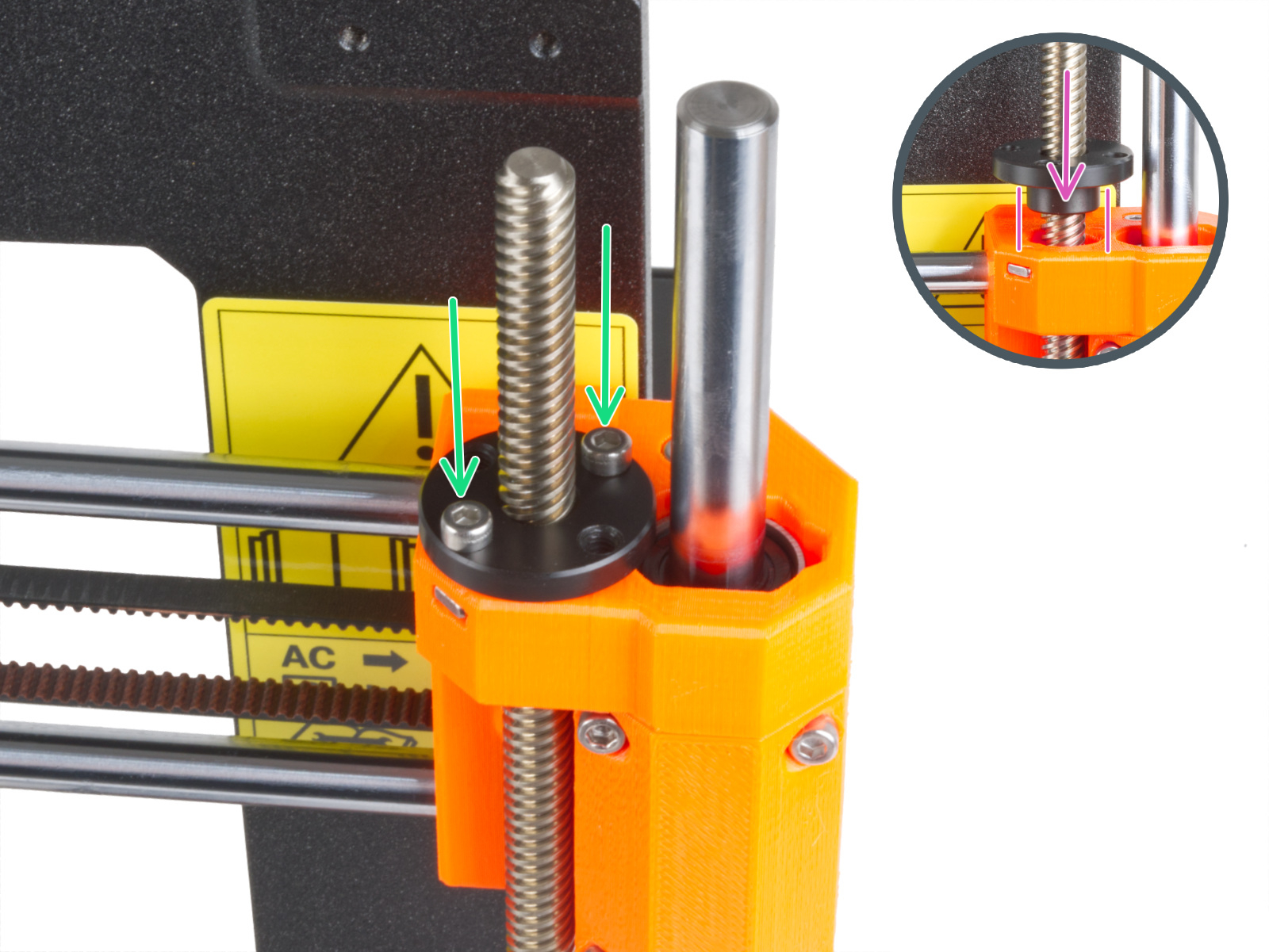
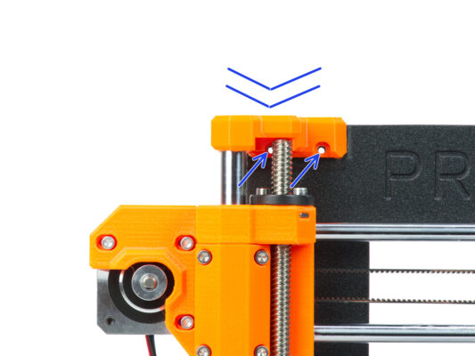
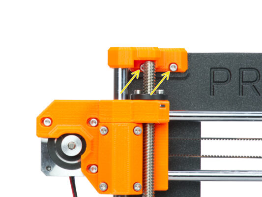
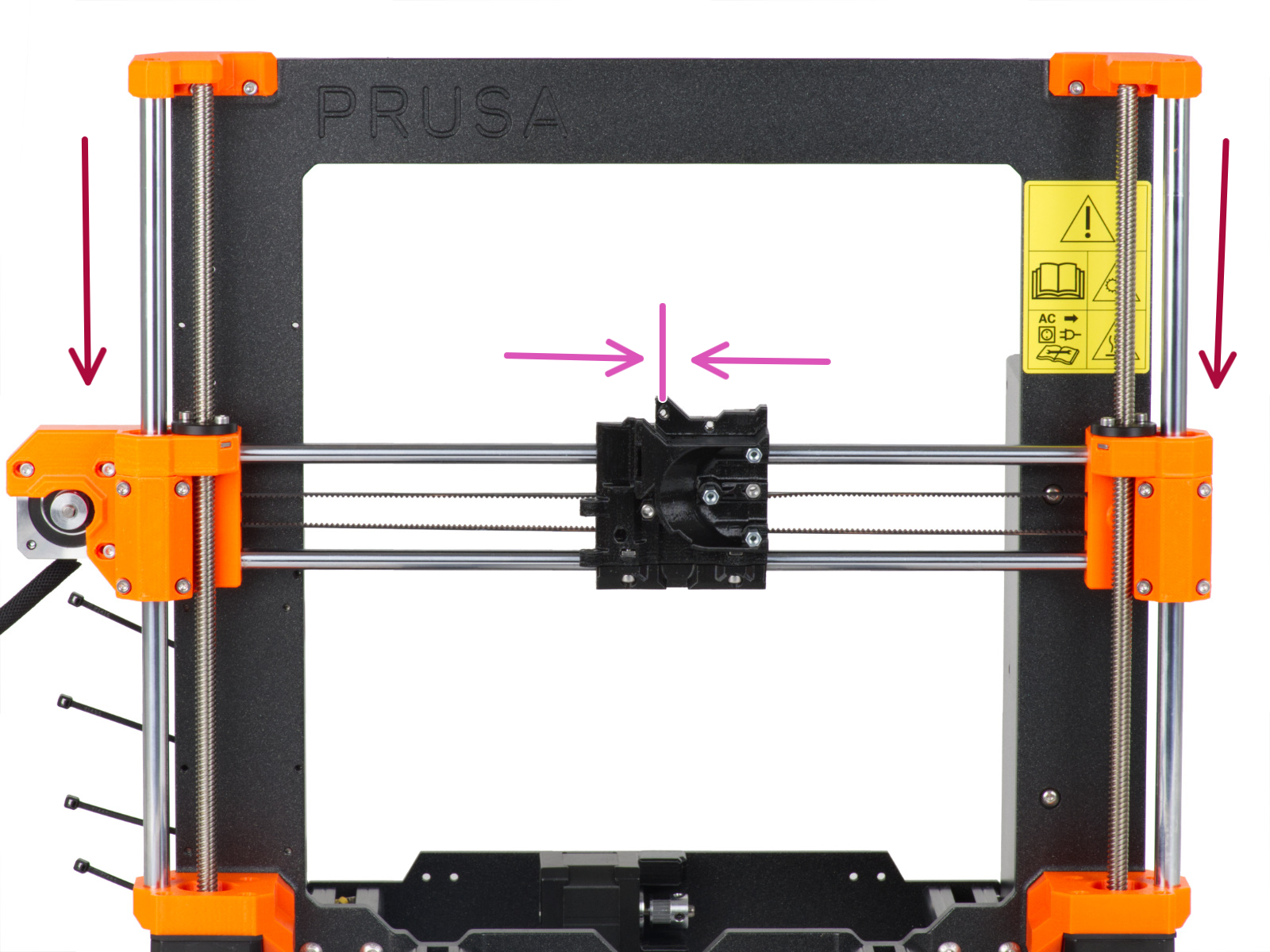
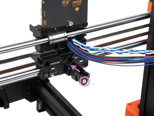
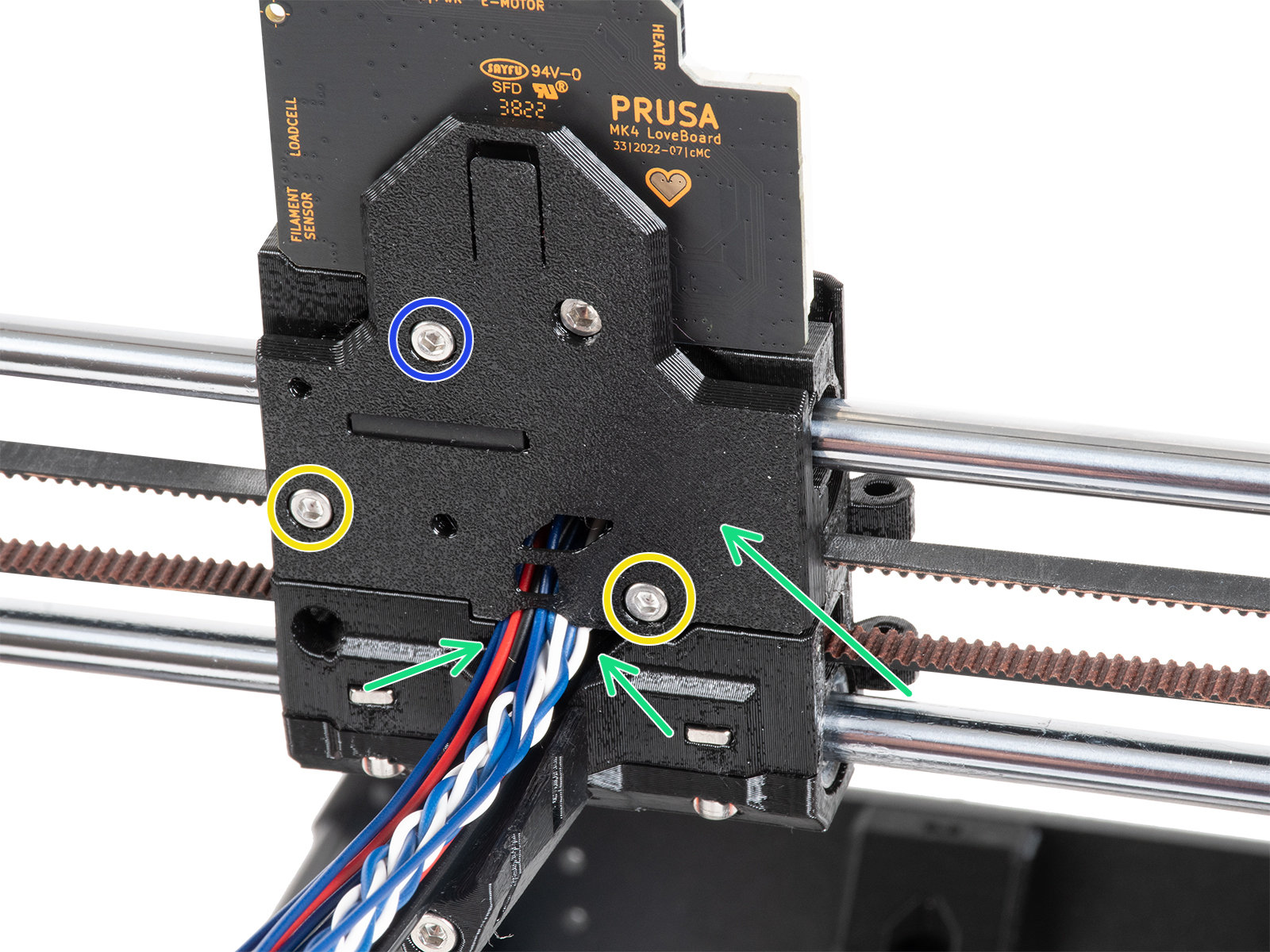
By carefully and gradually tightening the individual screws holding the Z motor, align the threaded rod in the X-end-idler. Watch the threaded rod move while tightening. Tightening the right front screw tilts the top of the rod to the rear left - and vice versa. Tighten all screws firmly.


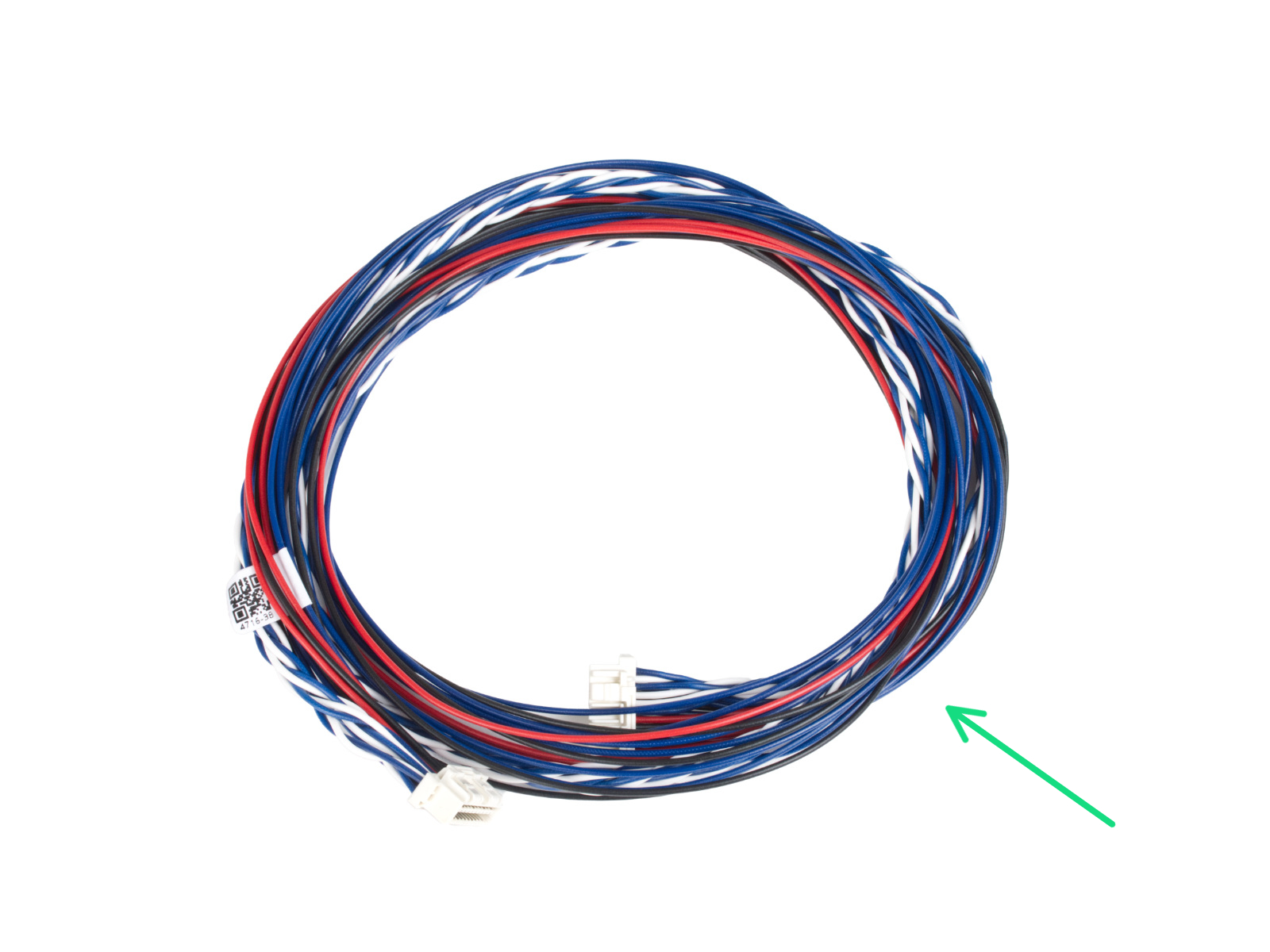

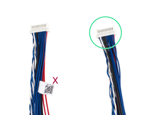

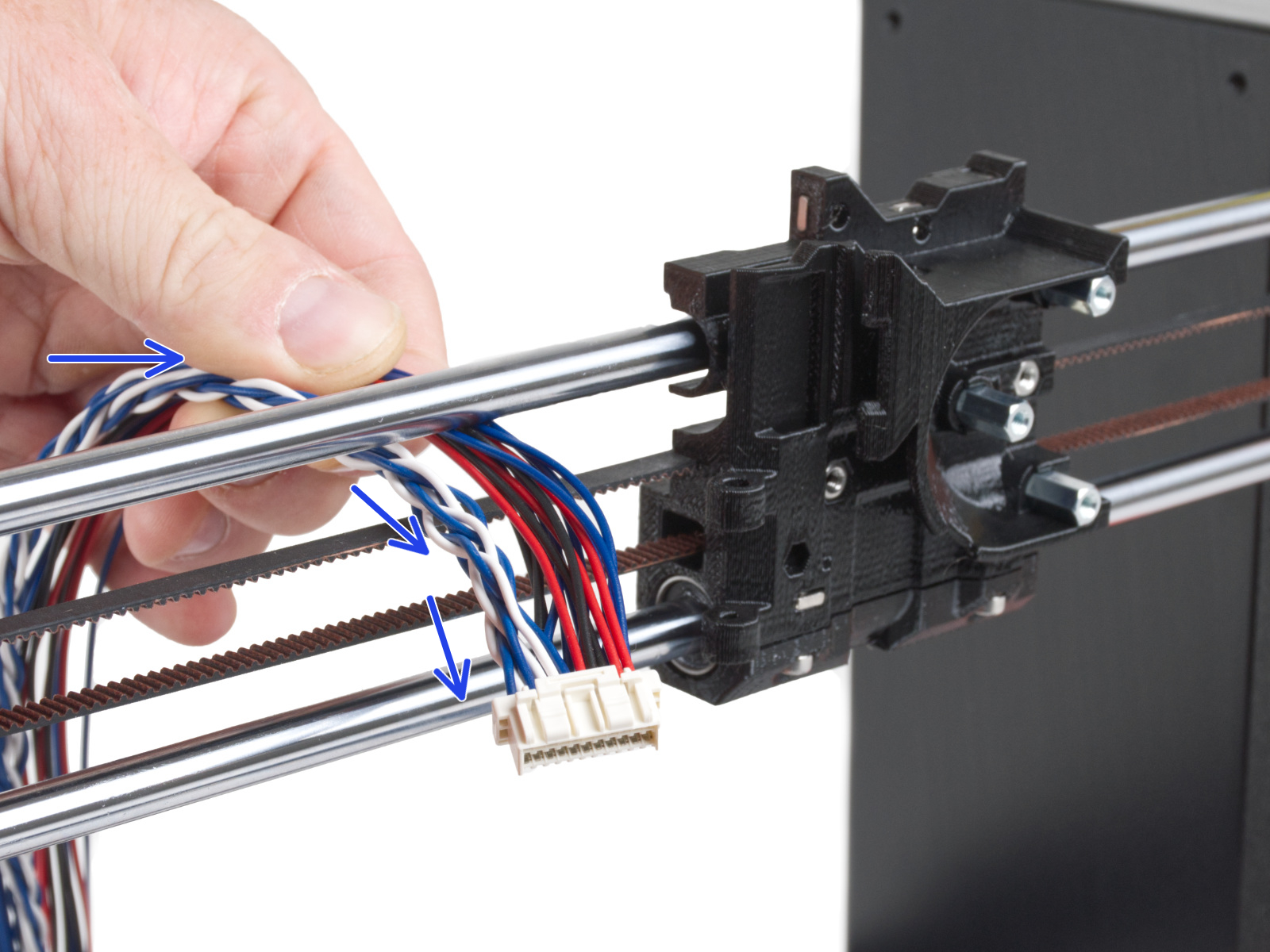
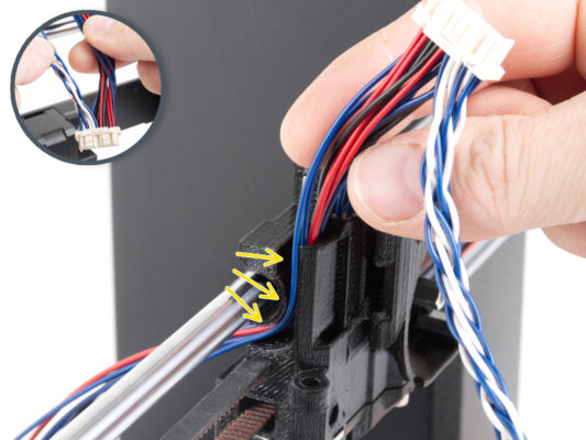
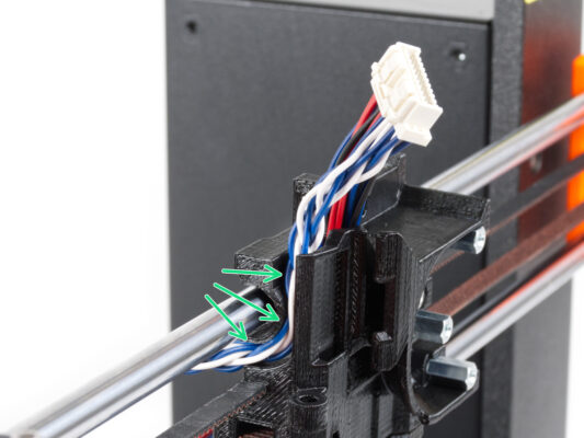


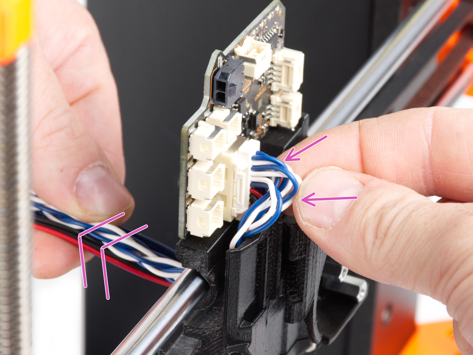
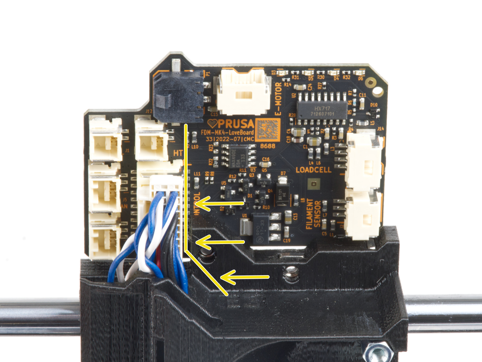


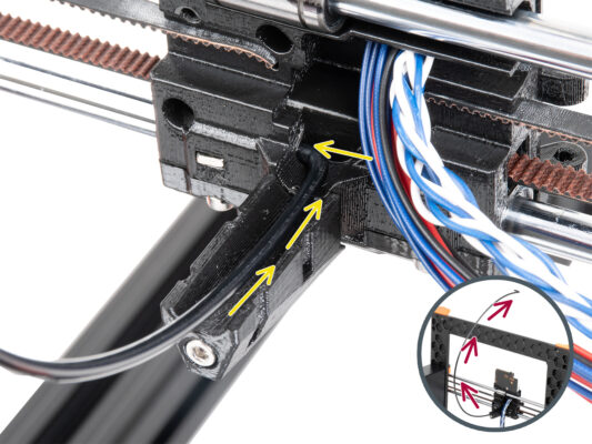

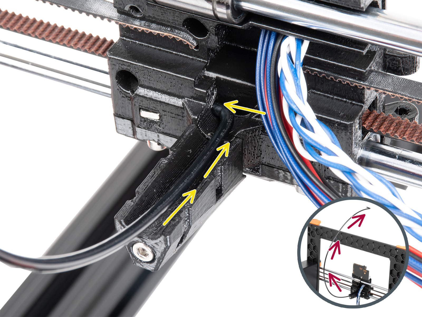
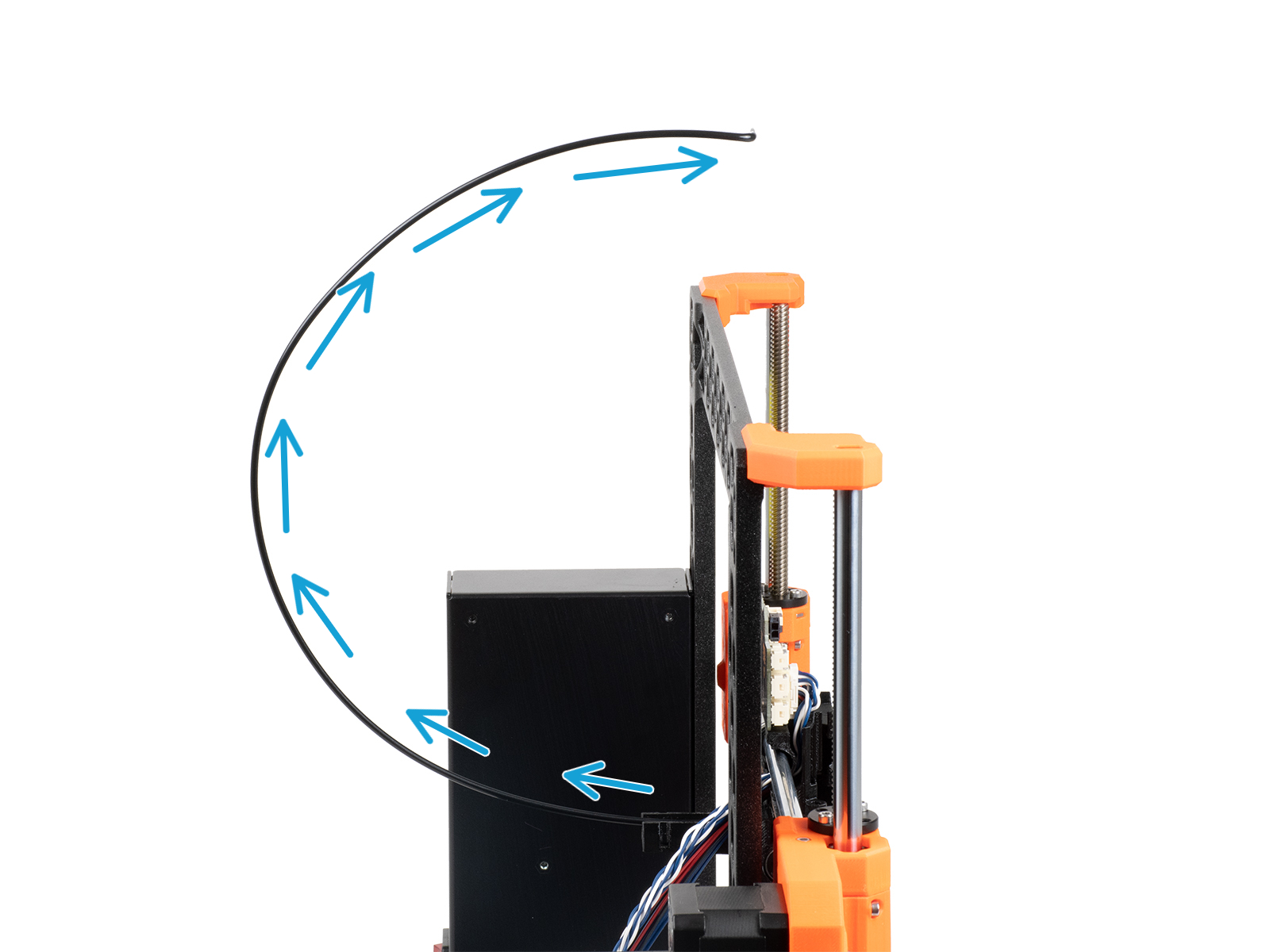


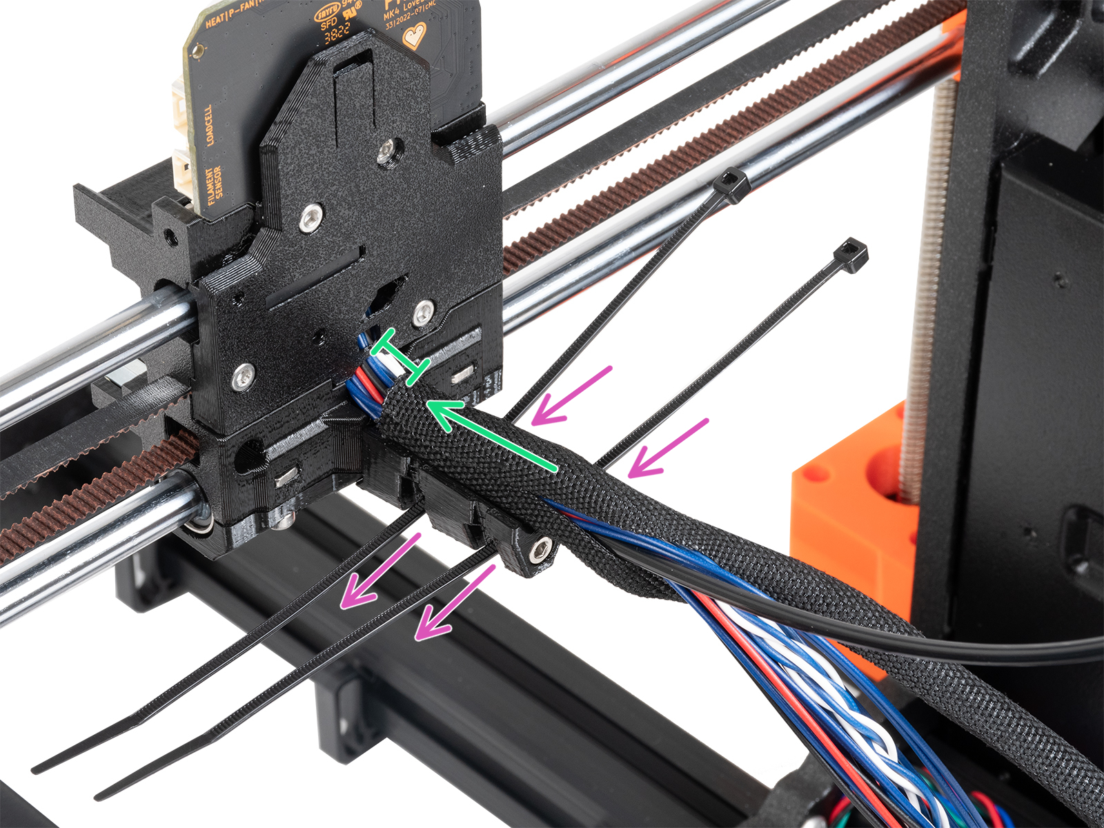
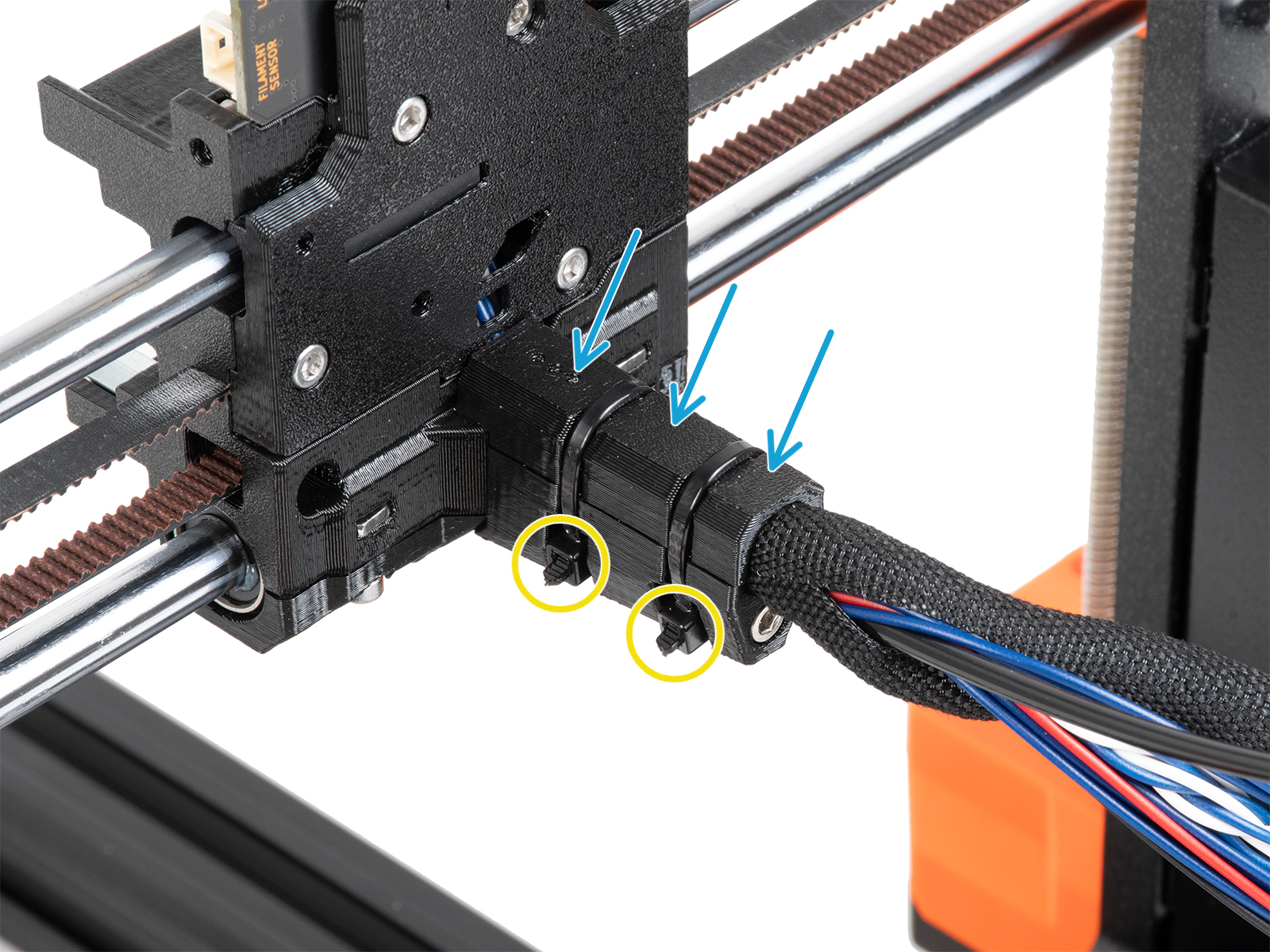

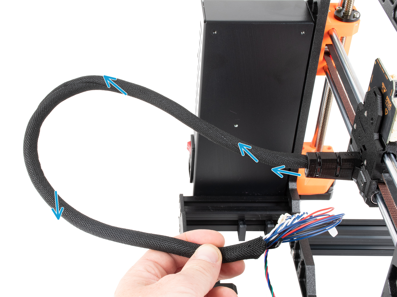

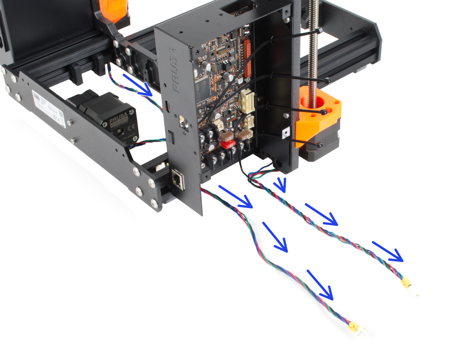
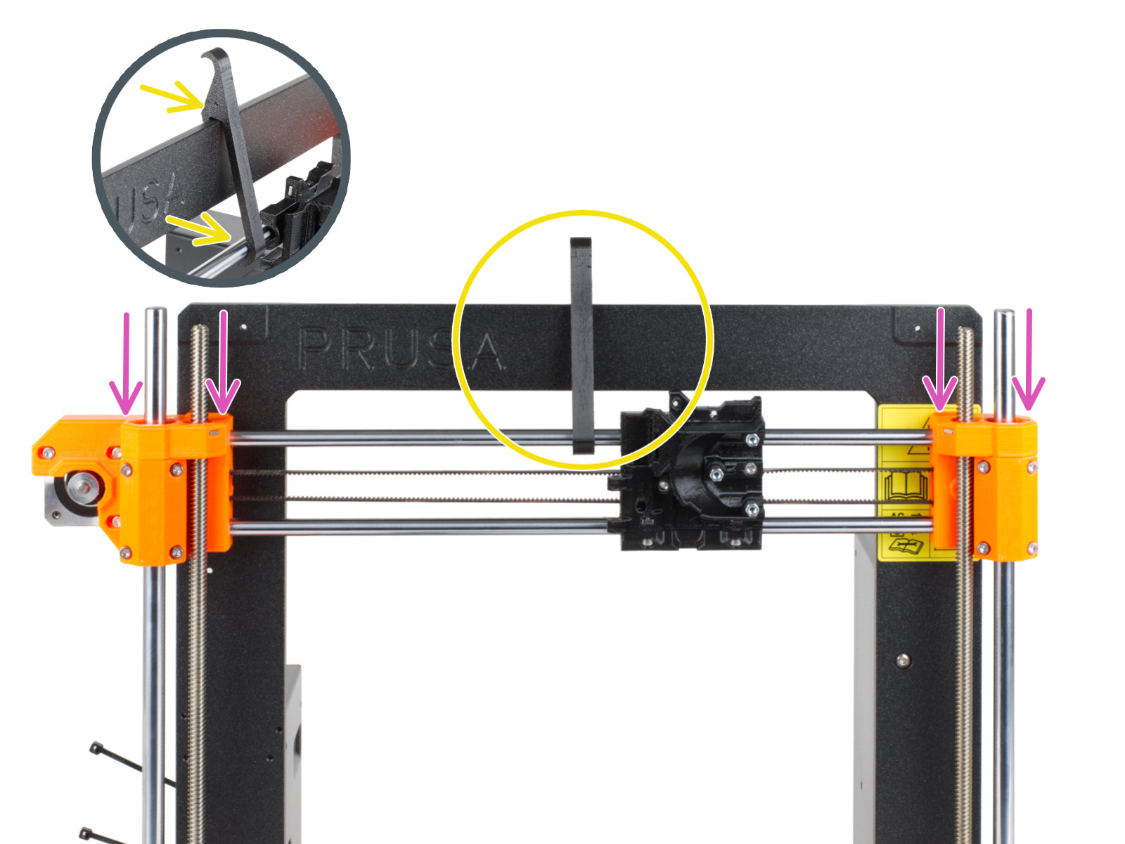
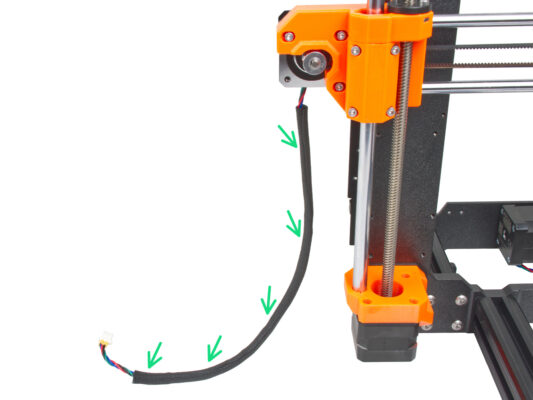
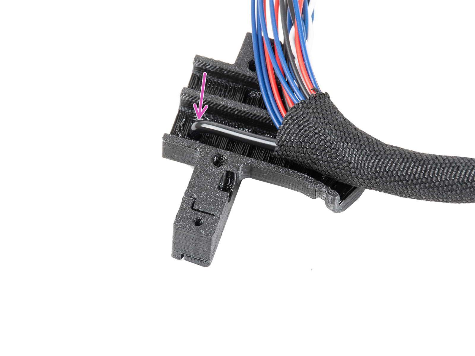
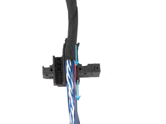
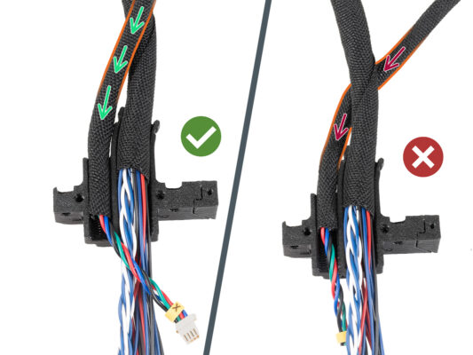
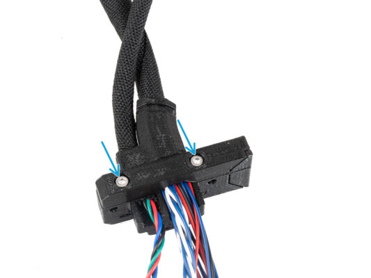
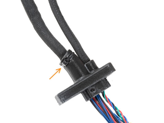
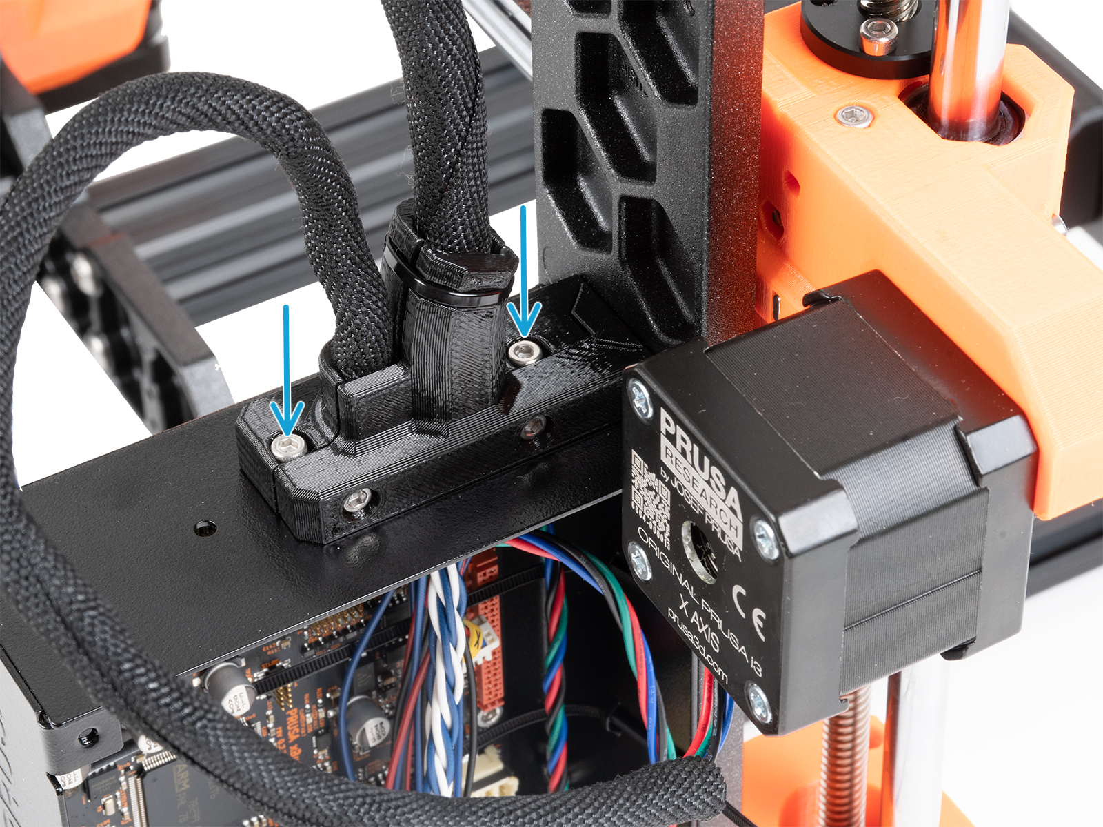
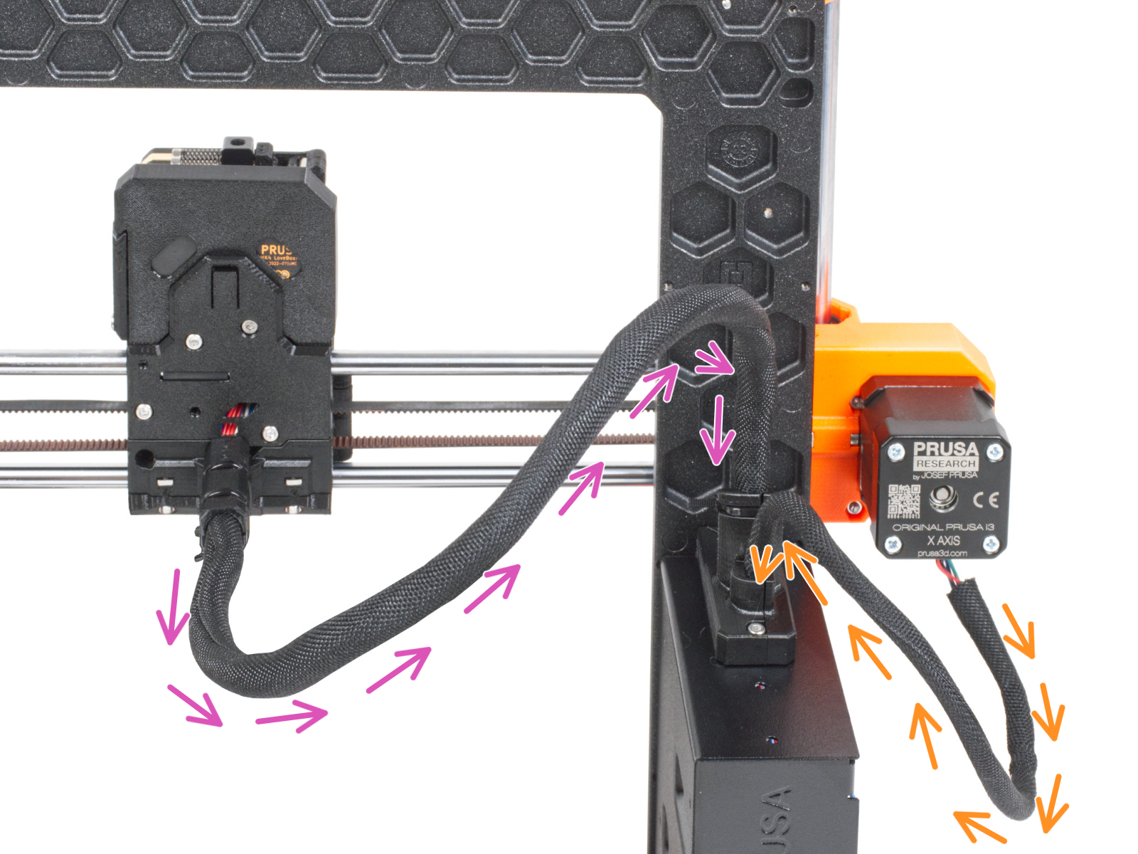
Hold the cable bundle upwards while wrapping and continue until it is fully wrapped.


If you have a question about something that isn't covered here, check out our additional resources.
And if that doesn't do the trick, you can send an inquiry to [email protected] or through the button below.

