⬢For this chapter, please prepare:
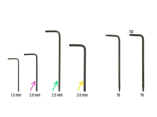
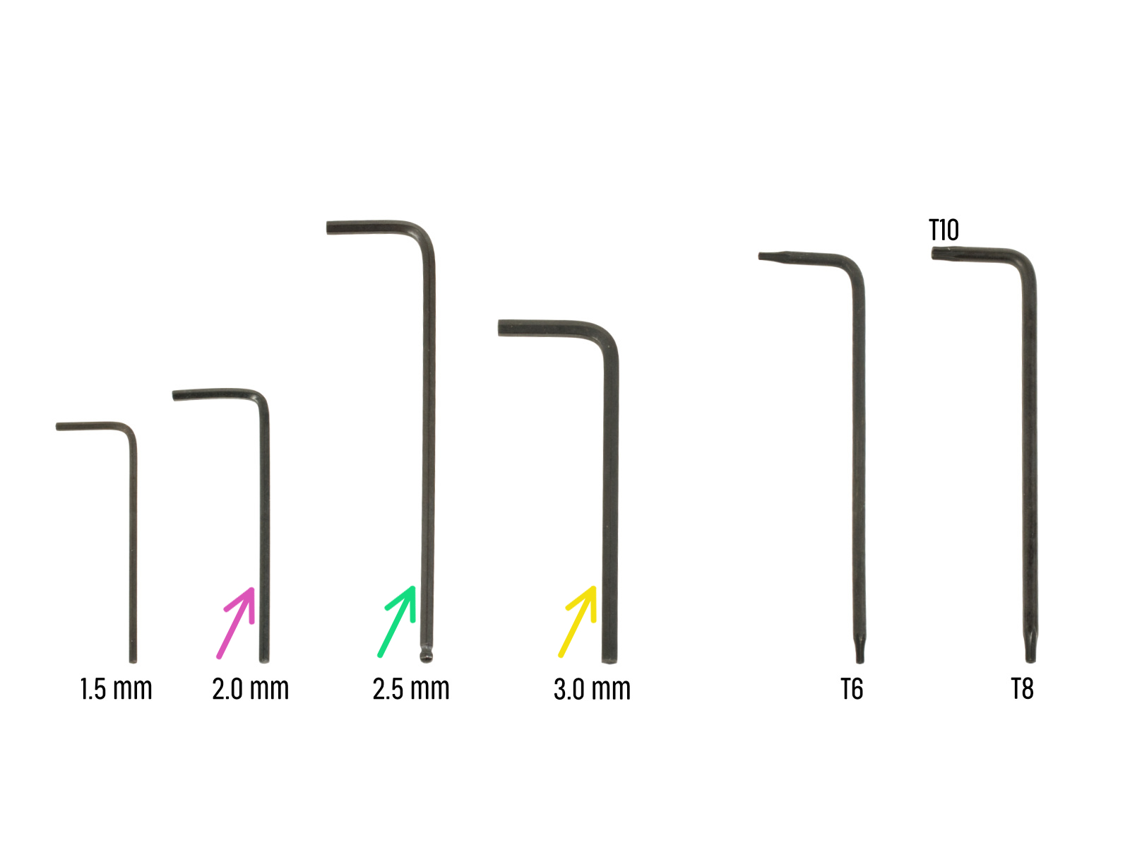
⬢2.0mm Allen key for tightening the grub screws
⬢2.5mm Allen key for most of the M3 screws on the assembly
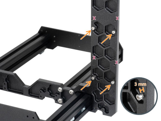
⬢3mm Allen key for M5 screws used on the frame


If you have a question about something that isn't covered here, check out our additional resources.
And if that doesn't do the trick, you can send an inquiry to [email protected] or through the button below.

