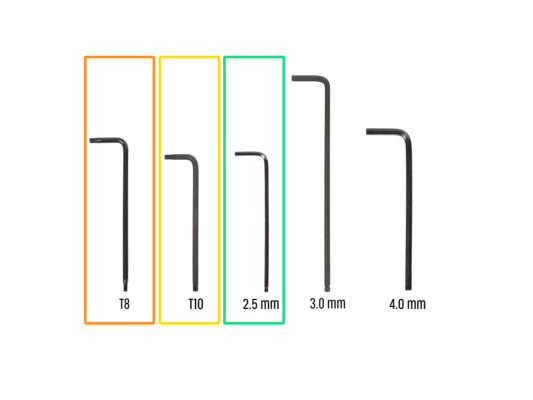


⬢T8 Torx key
⬢T10 Torx key (T10 Torx screwdriver)
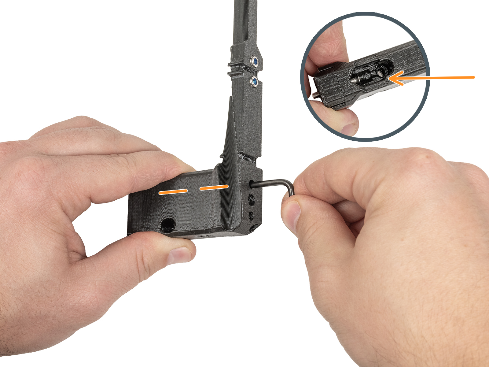
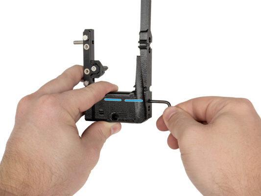
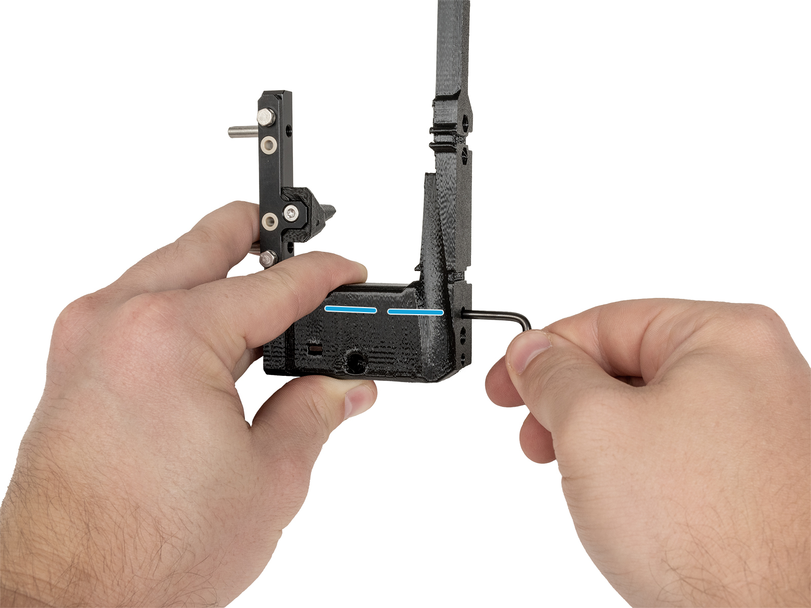
⬢2.5 mm Allen key
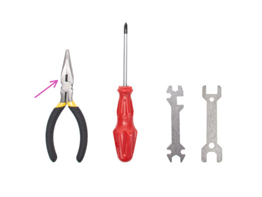
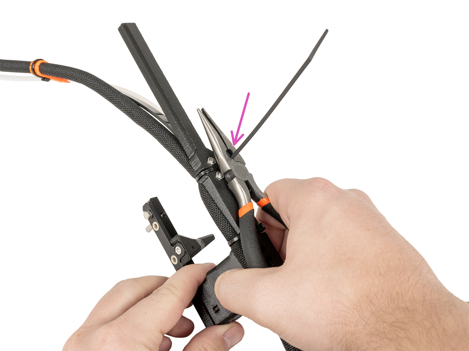
⬢Needle-nose pliers for cutting zip ties


If you have a question about something that isn't covered here, check out our additional resources.
And if that doesn't do the trick, you can send an inquiry to [email protected] or through the button below.

