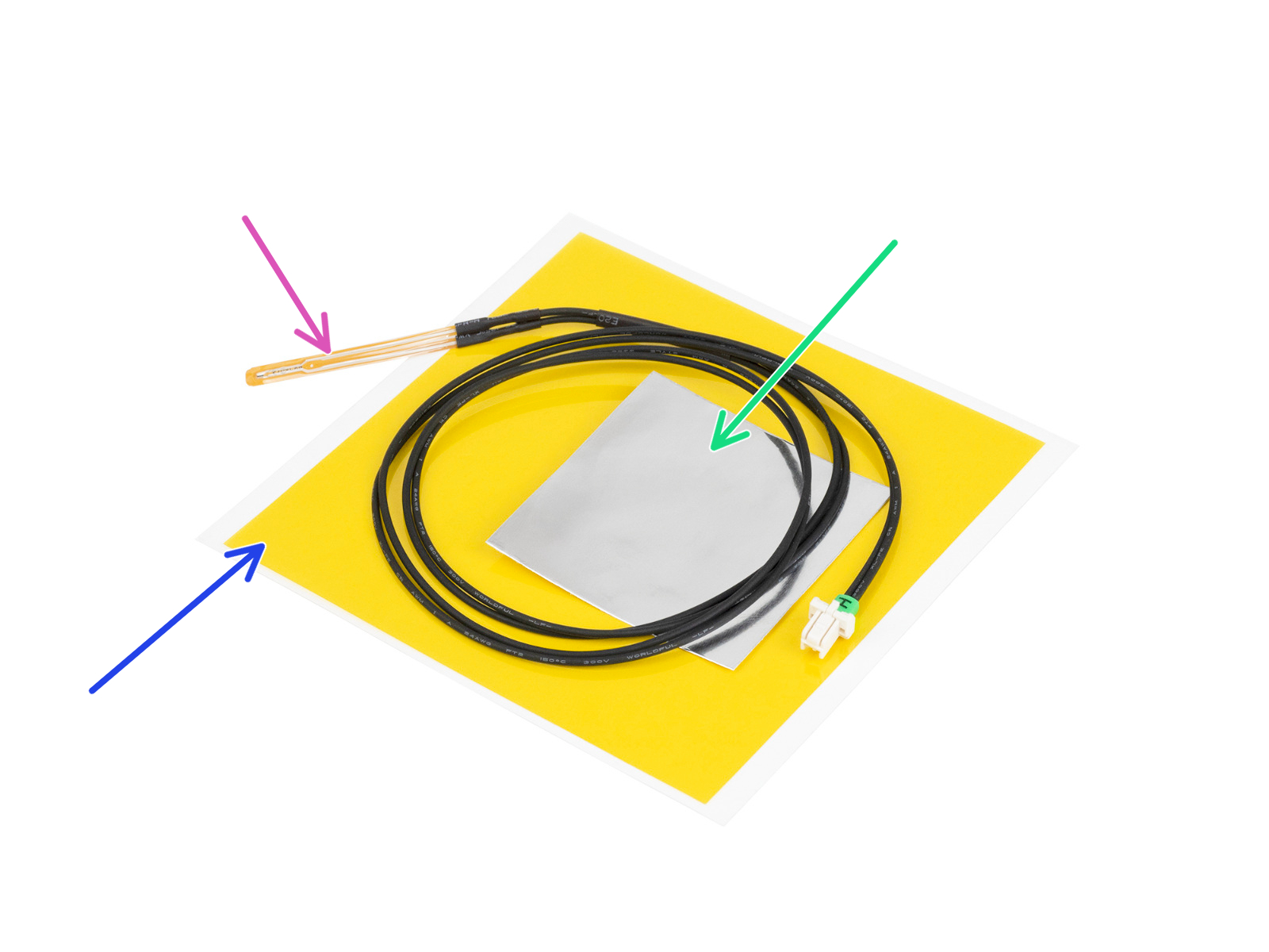
In the upcoming steps, you will replace the old heatbed thermistor (from your previous printer model) with a new version that is compatible with MK4, MK3.9, and MK3.5.
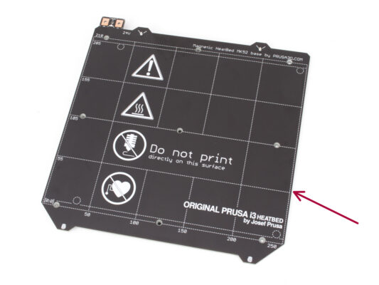
If you purchased a new heatbed with the upgrade kit — commonly for users with printers featuring 2+1 screws on the old heatbed — ensure that the new thermistor is pre-installed. You can easily verify this by checking for a white connector at the end of the thermistor cable. The presence of this connector indicates that the new thermistor is already in place and you can skip to M3nEs nuts: parts preparation
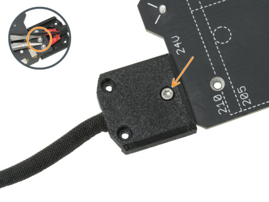
This part may vary slightly in the design of the cover, location of the screws and number of the screws.
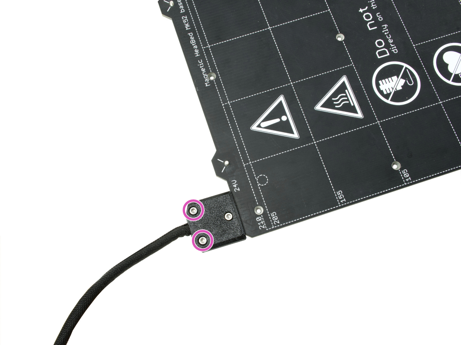
⬢Remove the screws fixing the cable bundle.
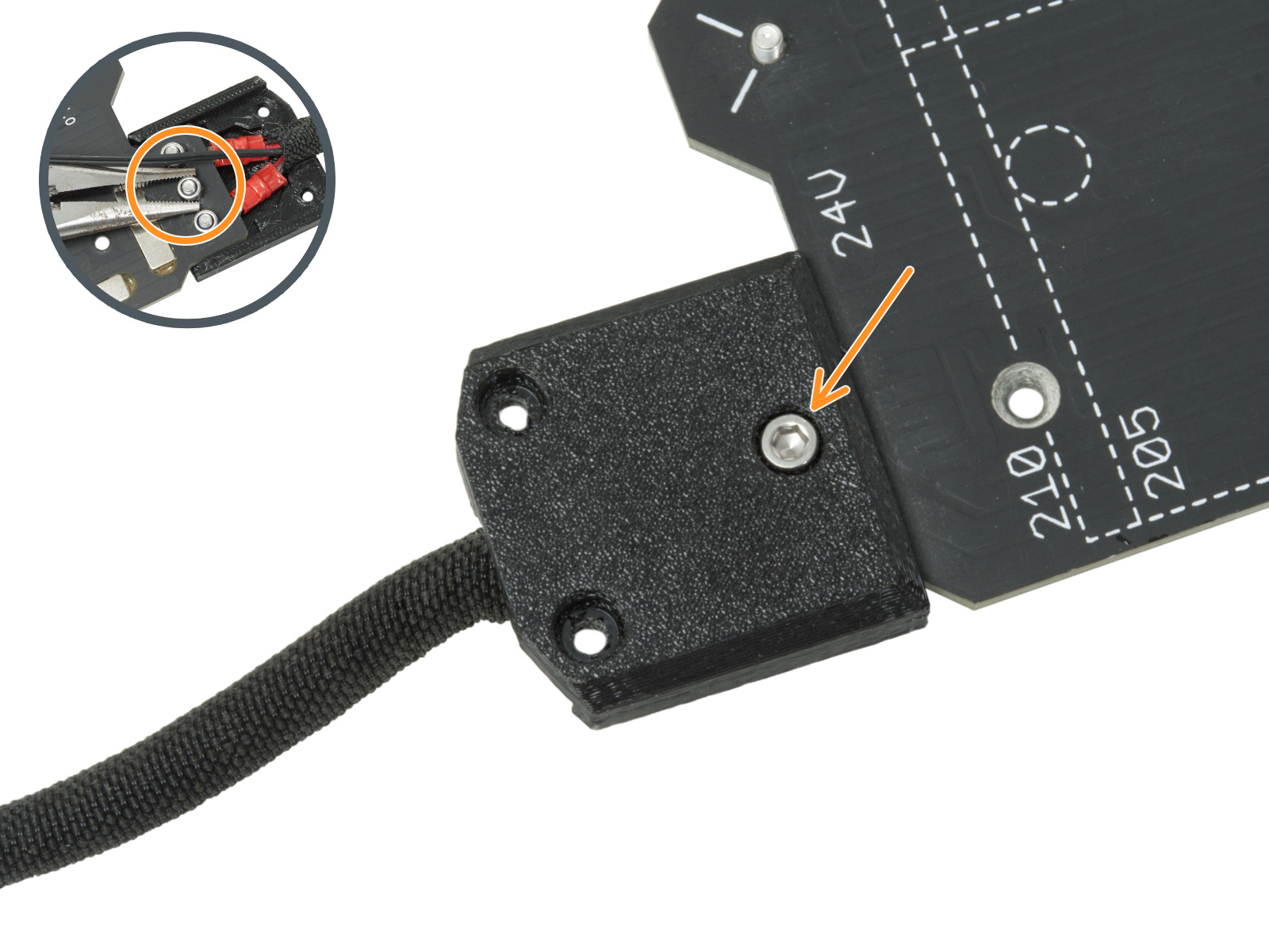
⬢Remove the screw securing the cover. From the underside, grasp the middle M3nN nut with the pliers while loosing the screw.
⬢Remove the cover.
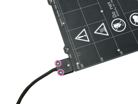
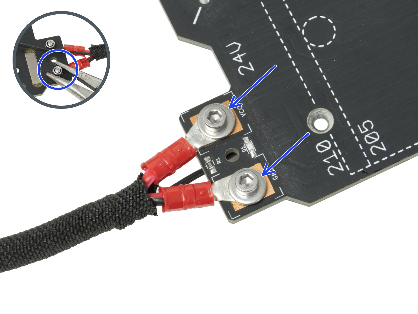
⬢Release the screws fixing the heatbed power cables and remove the cables from the heatbed. From the underside, grasp the M3nN nuts with the pliers while loosing the screws.
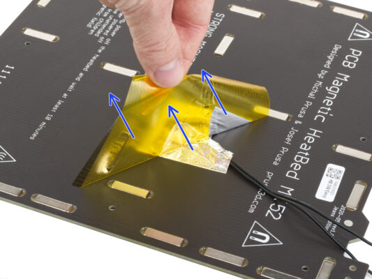
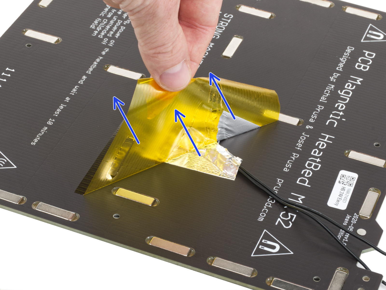
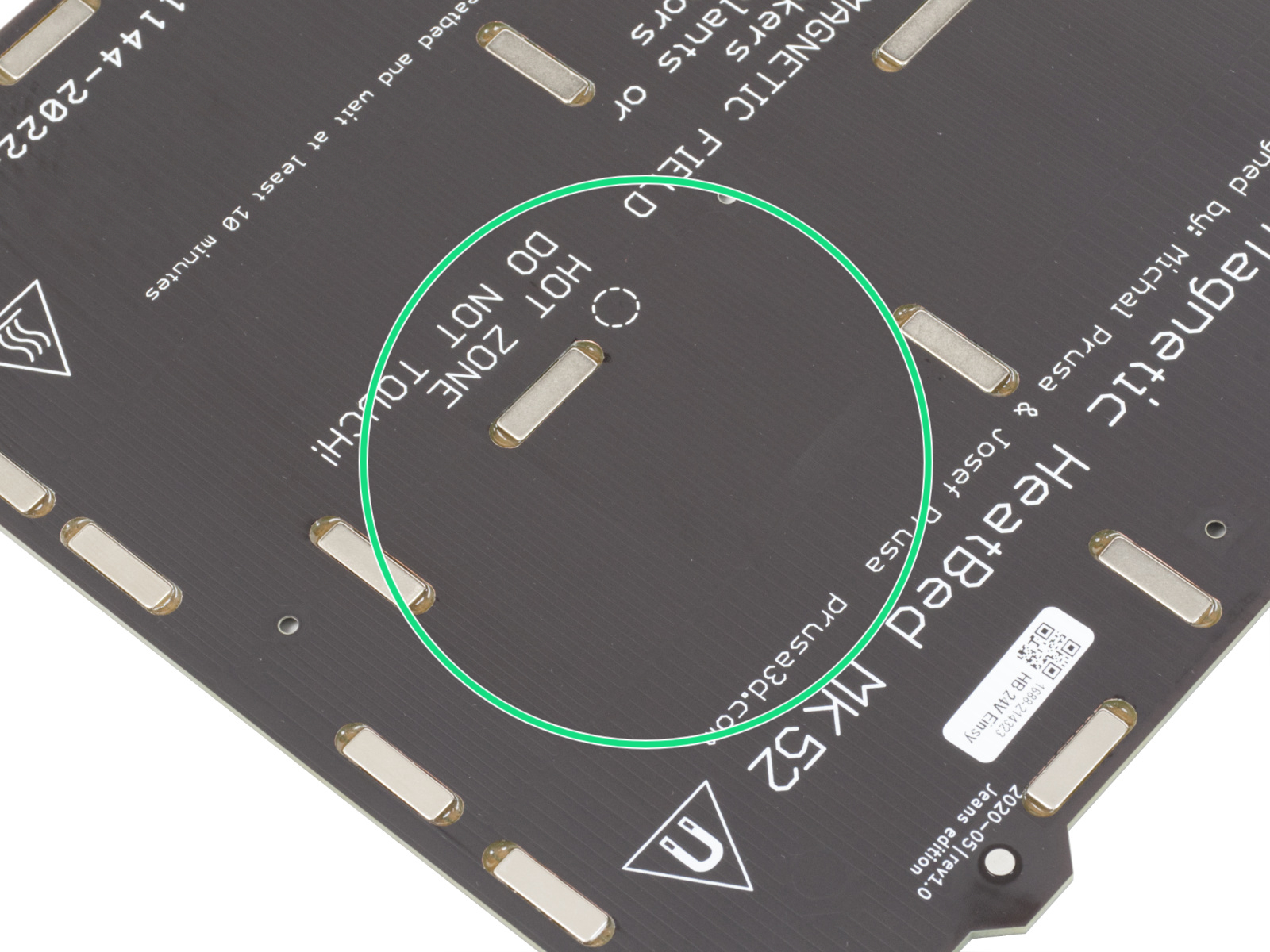
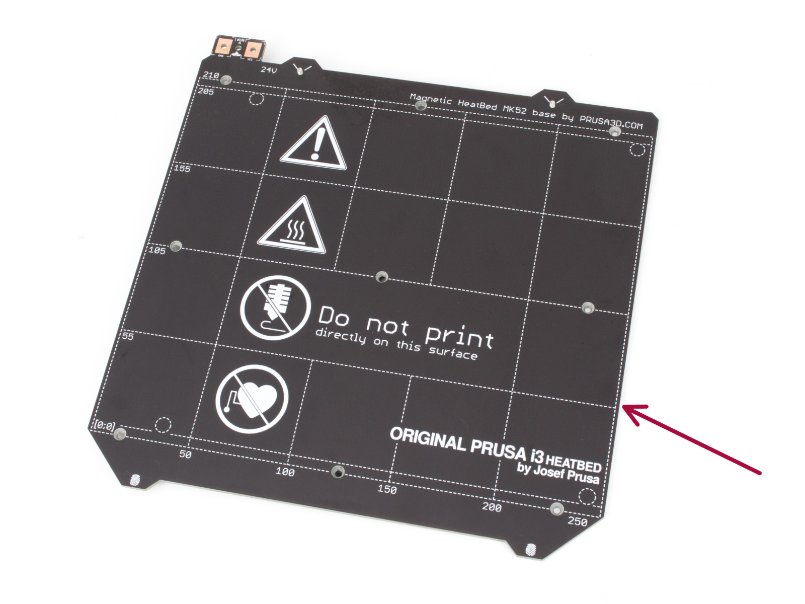
⬢After you have removed the thermistor and the tapes, clean the entire board to remove any grease. You can leave the glue, which was under the aluminum tape.
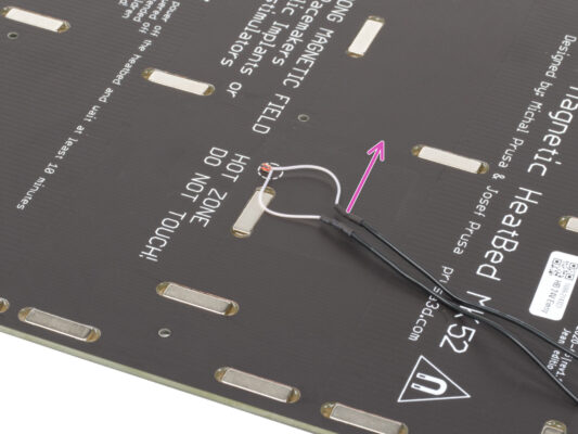
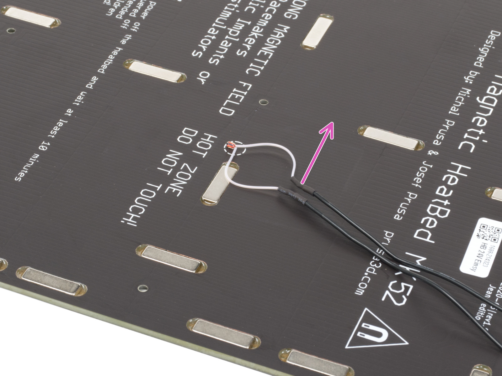
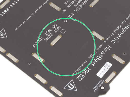
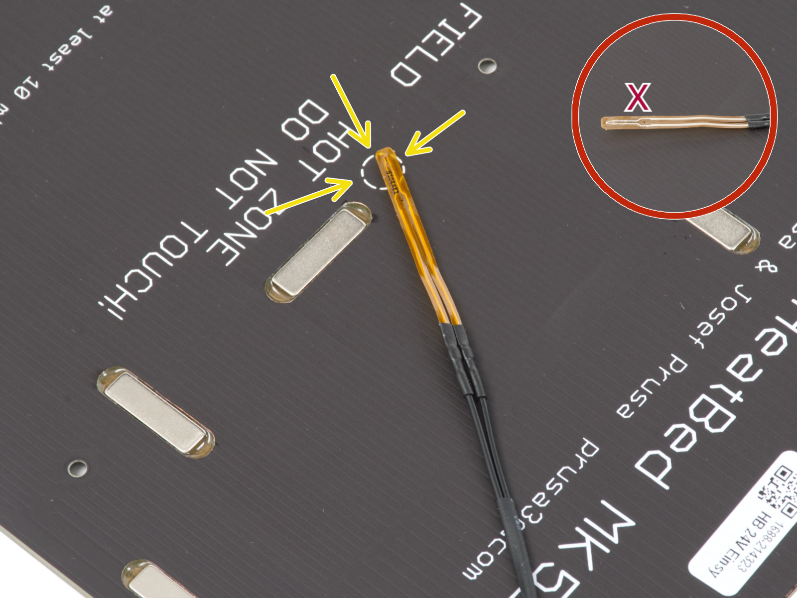
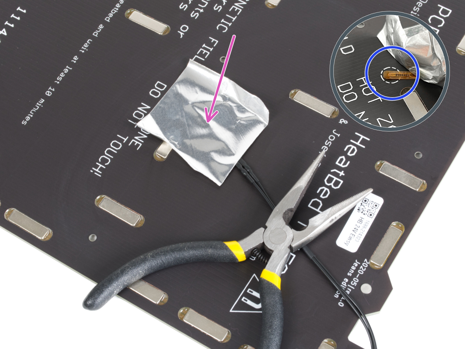
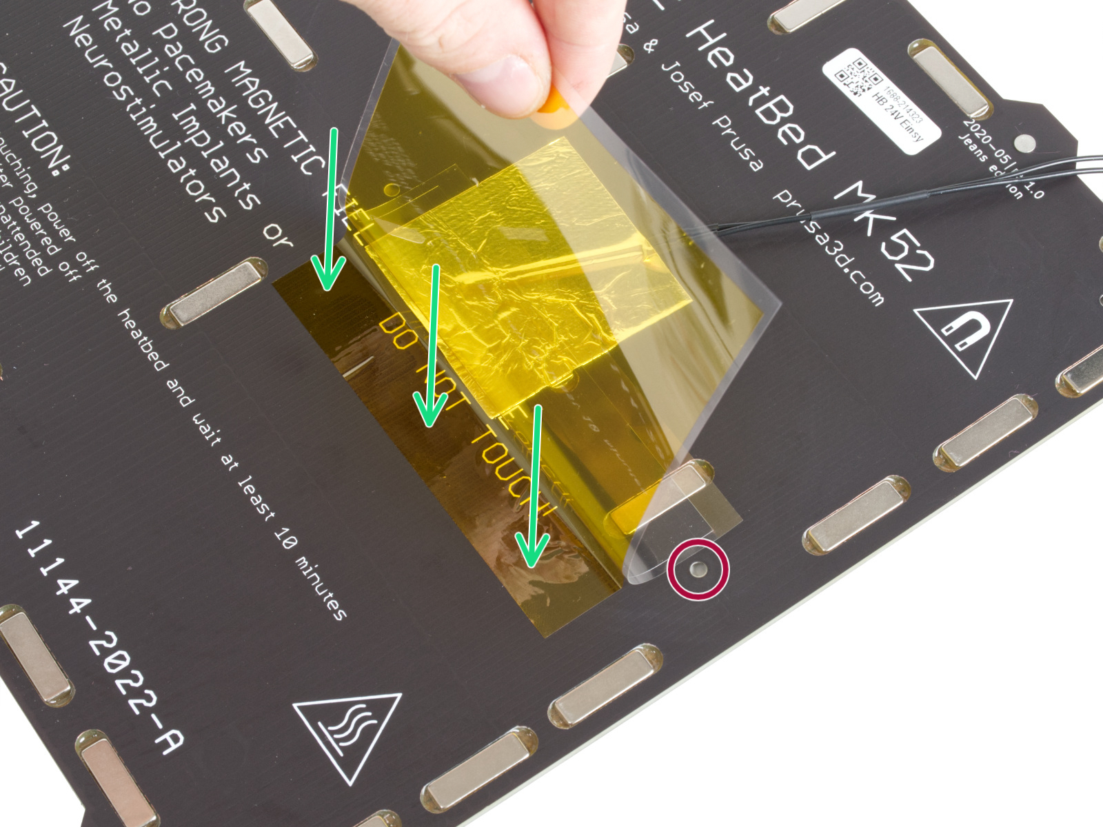
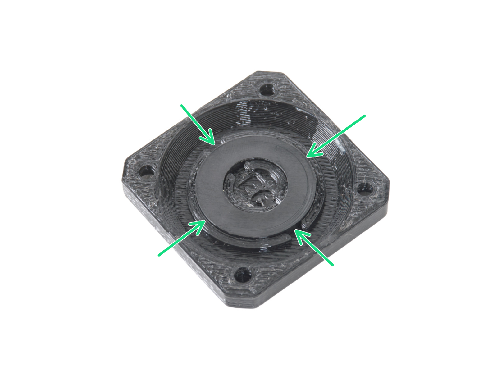
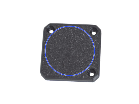
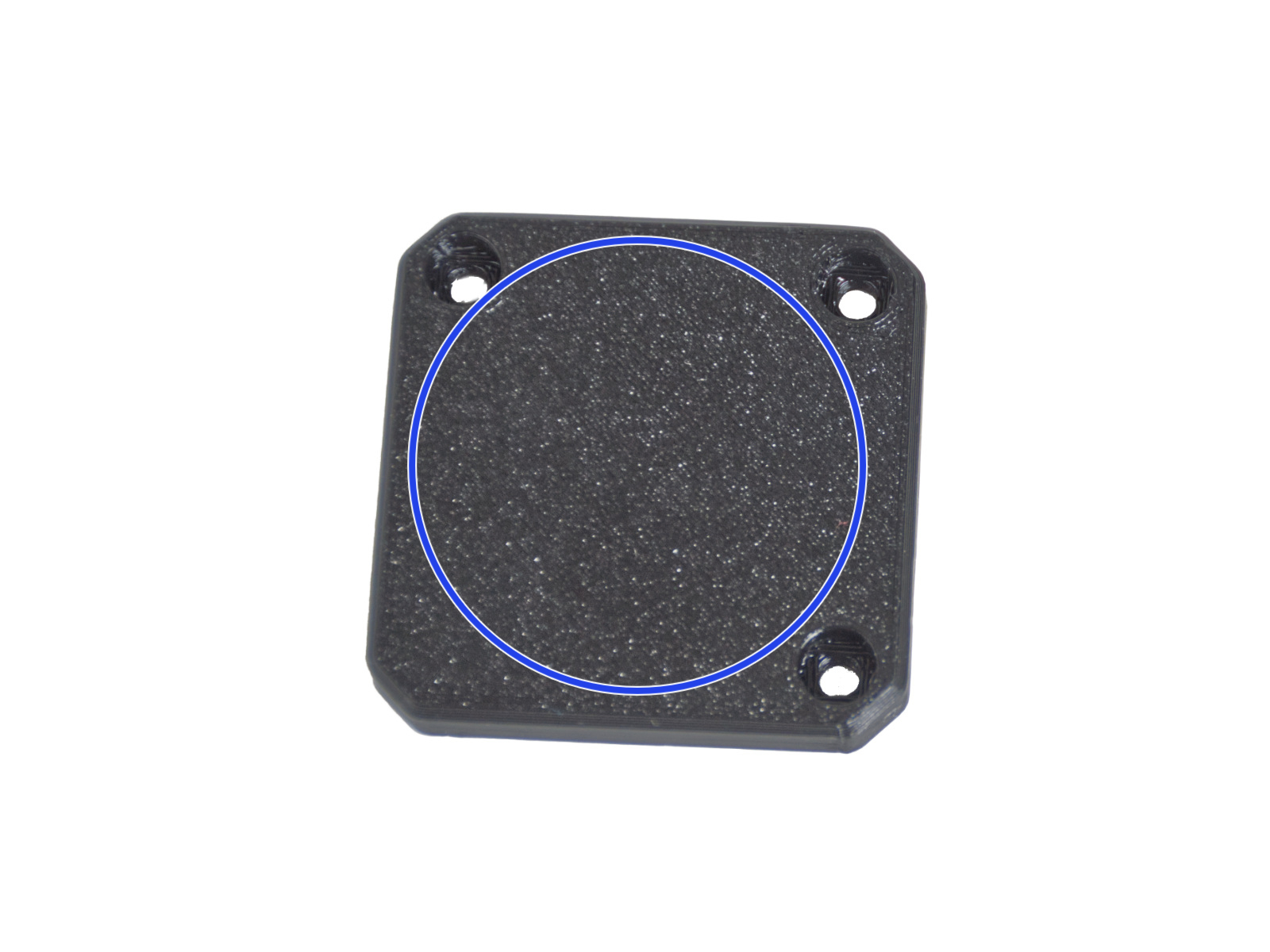
⬢Place the thermistor on the heatbed. The tip of the thermistor must be in the circle.
If you miss this spot, the printer will read incorrect temperature values.
Note which side the sensor is attached to the heatbed.
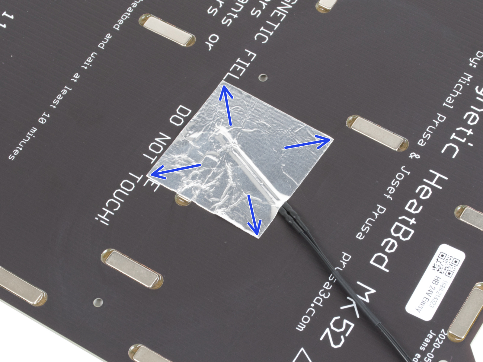
⬢Take the silver aluminium tape and carefully peel off the protective film.
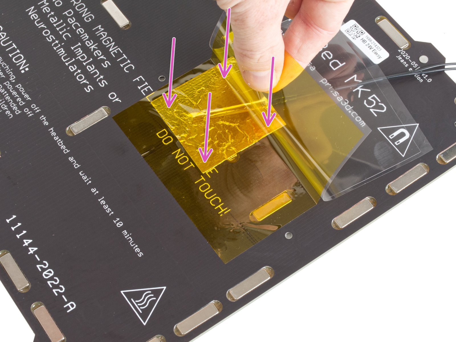
⬢Glue the tape to the heatbed, BUT ONLY in the centre of the thermistor (inside the circle shape). We need to double-check the correct position.
⬢Peel or bend the tape slightly, to reveal the tip of the thermistor.
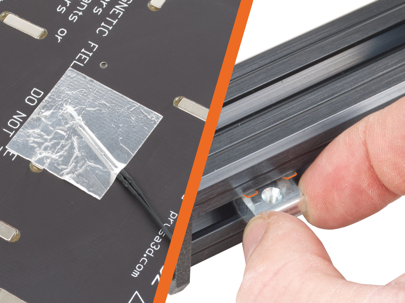
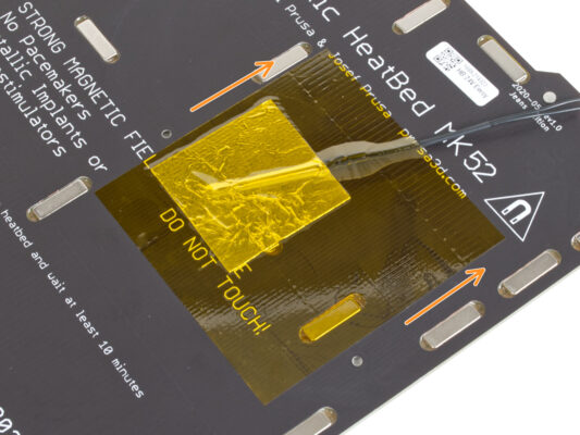
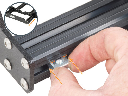
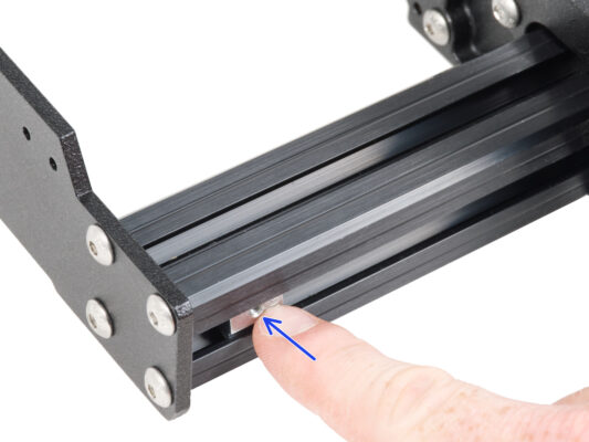
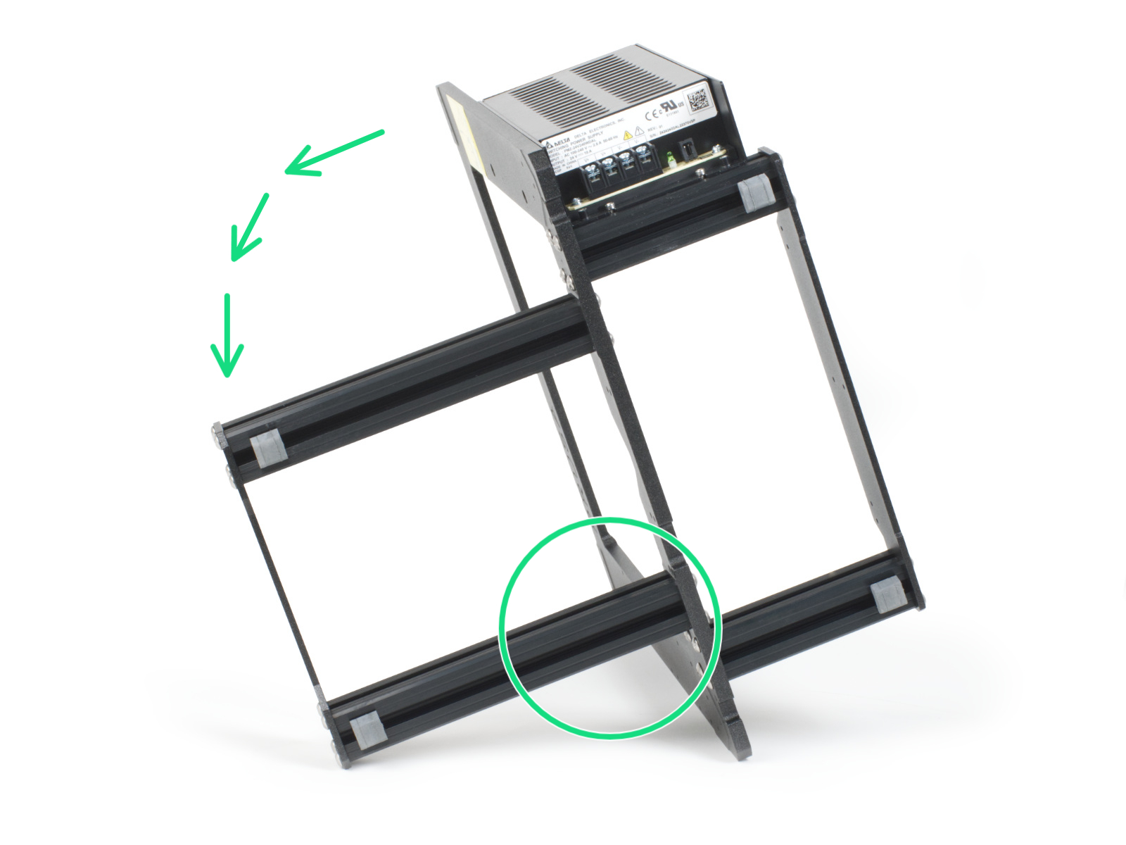
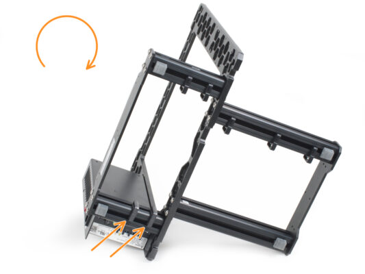
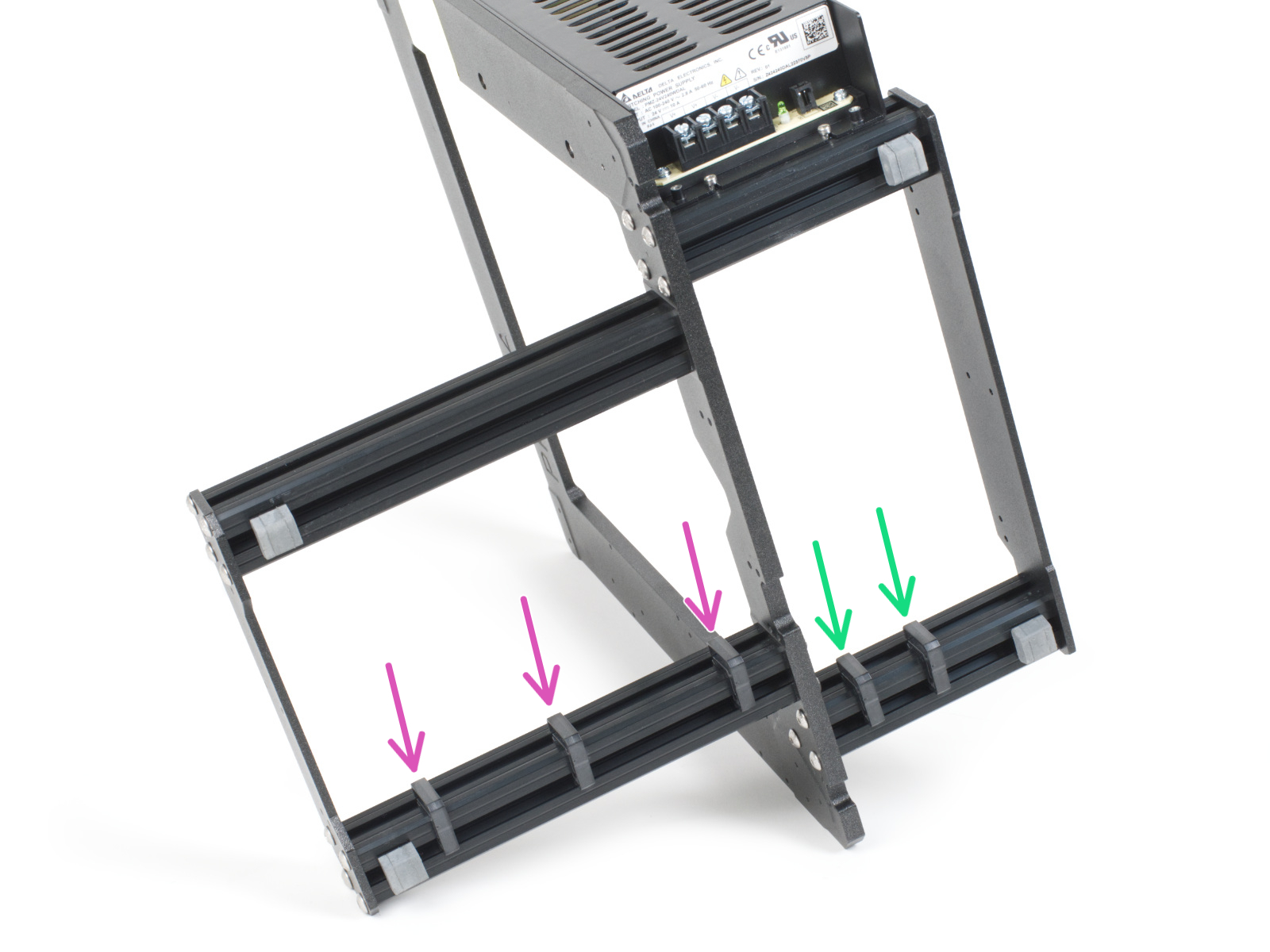
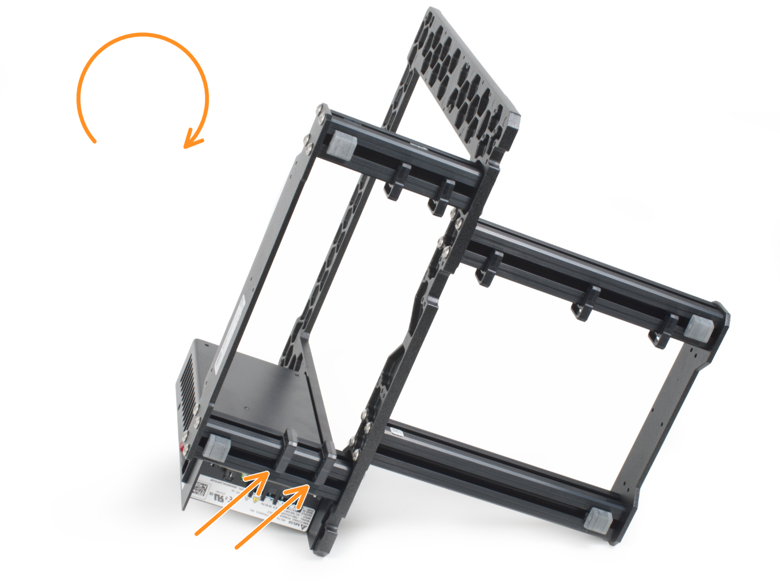
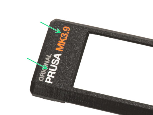
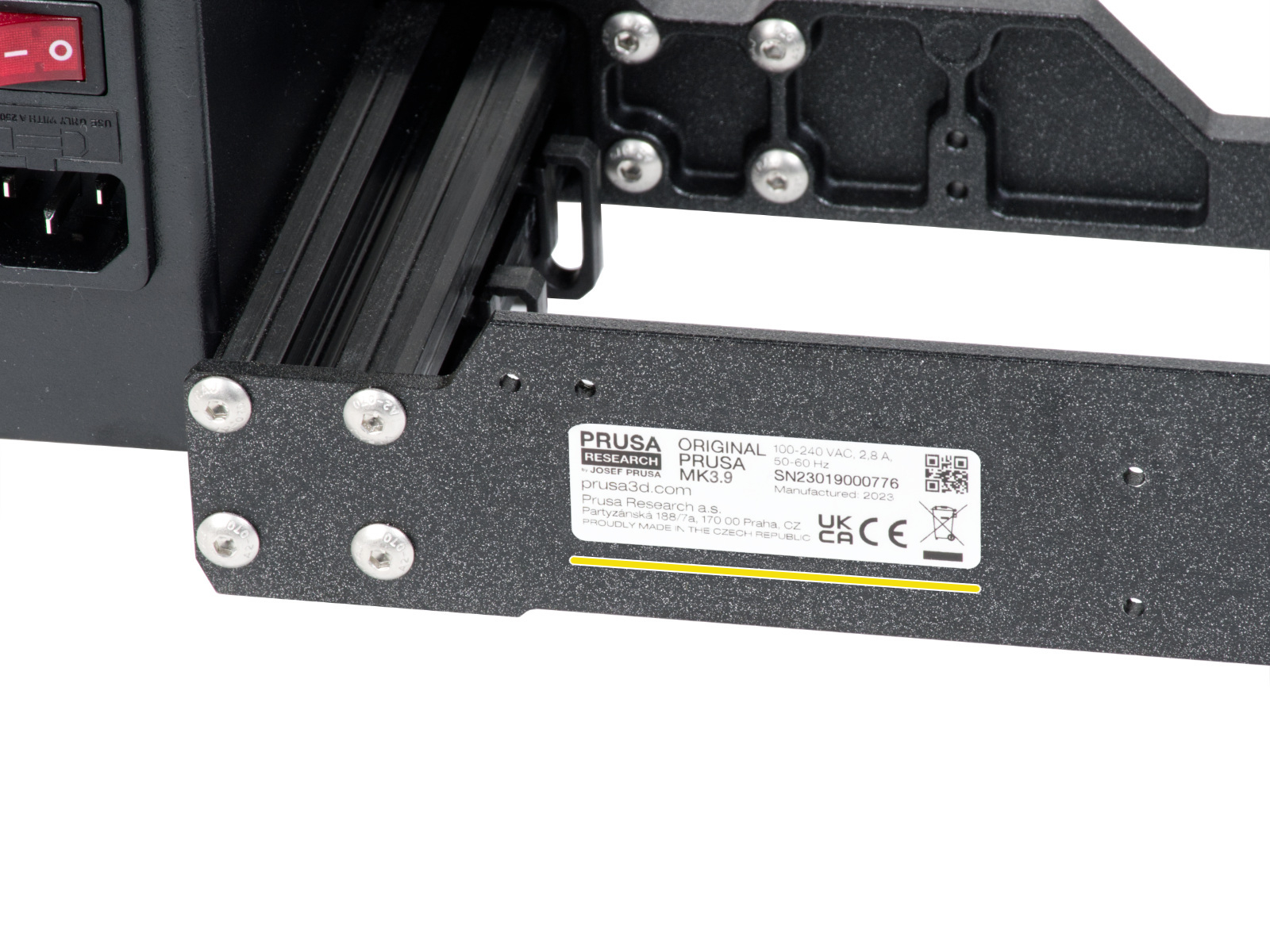
⬢Turn the frame like in the picture and focus on the marked area
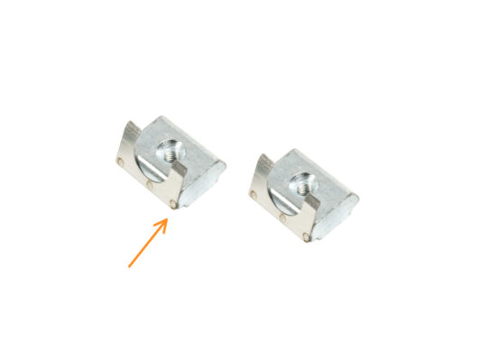
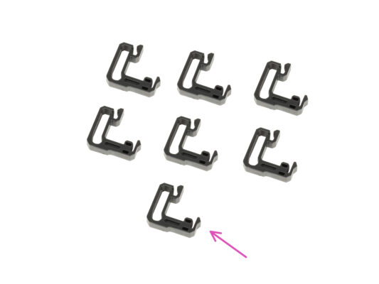
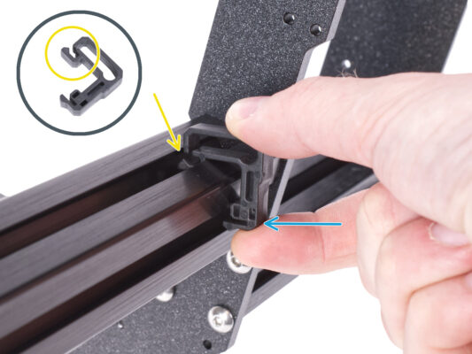
⬢Take one of the cable clips and hook the side with the clip into the inner groove of the lower longer extrusion. There is a hook on the part, see the detail.
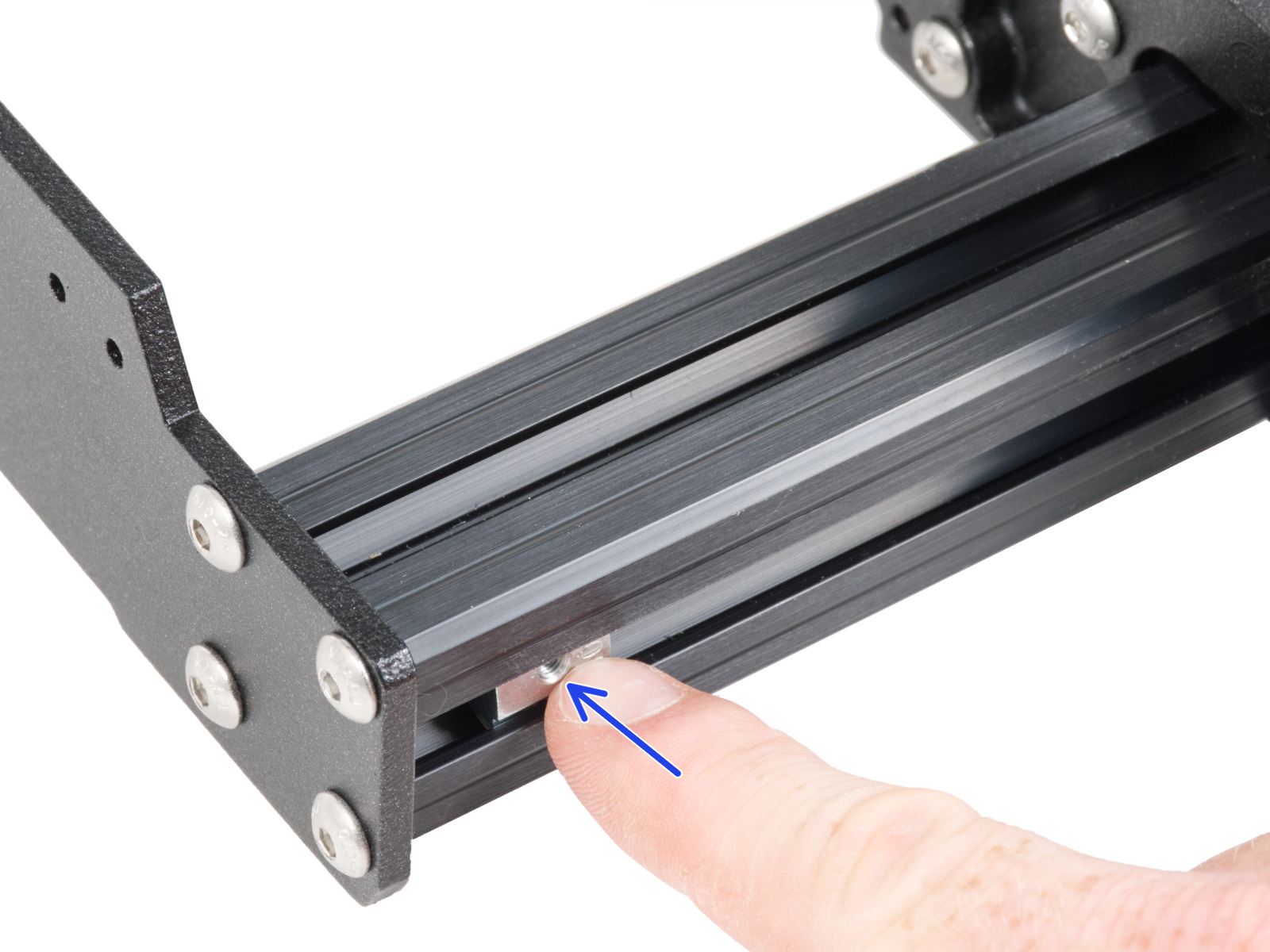
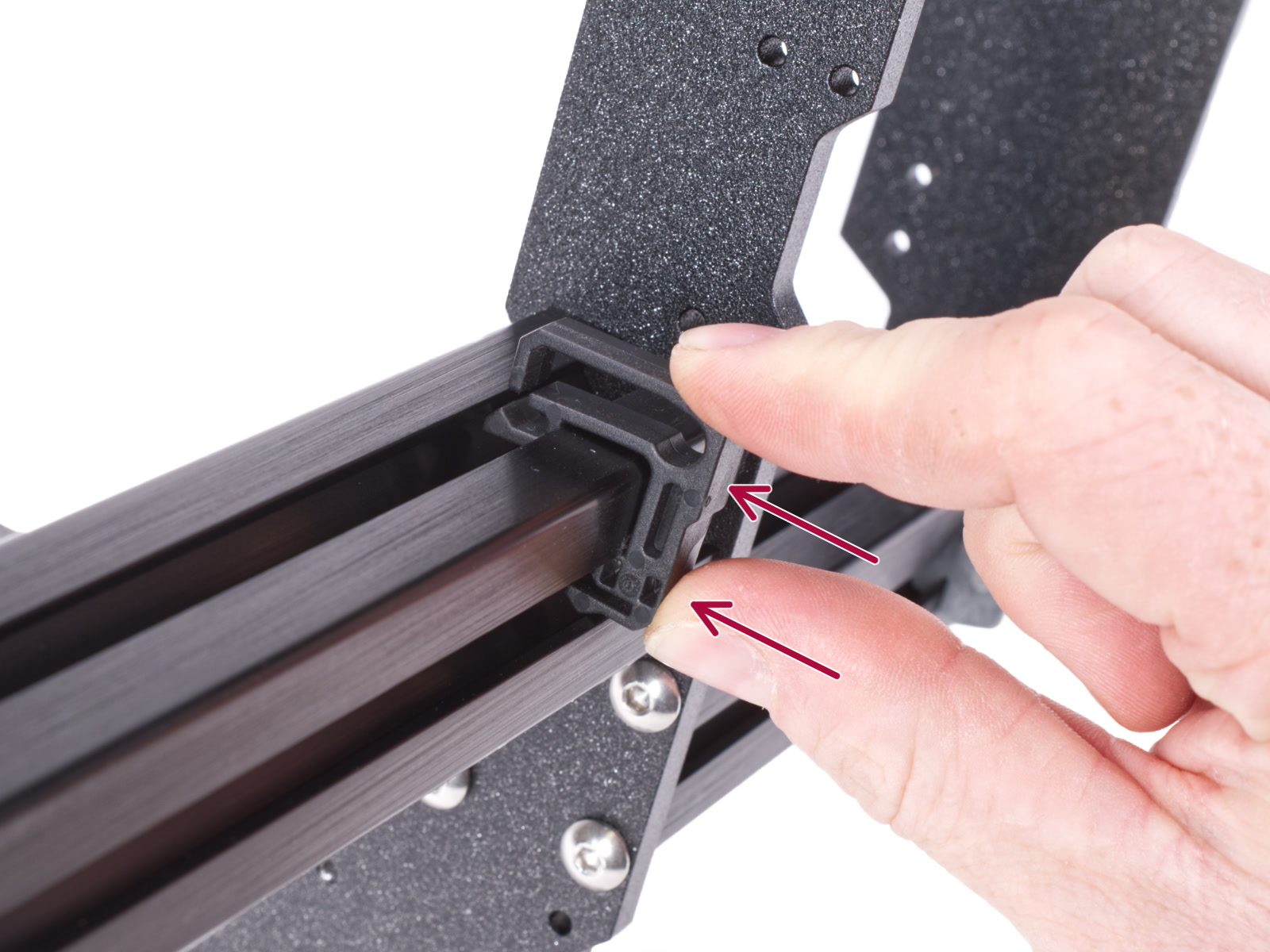
⬢Place the other end of the clip on the underside of the extrusion.
⬢Use more force to push on the bottom side of the cable clip. It must fit into the groove and you must feel it "click" in.
This and the following step are optional. Also, please BE PATIENT, smaller letters require more effort in order to be transfered and glued properly.
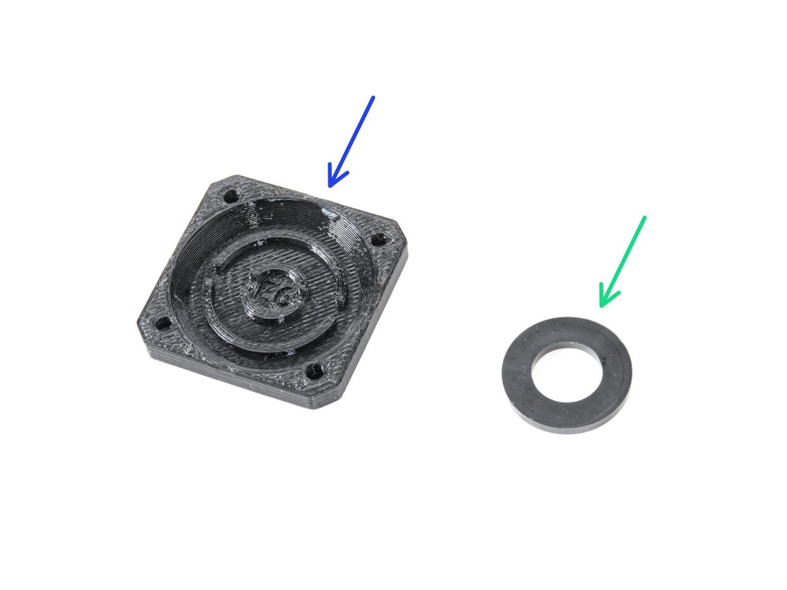
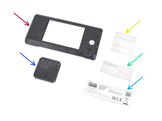
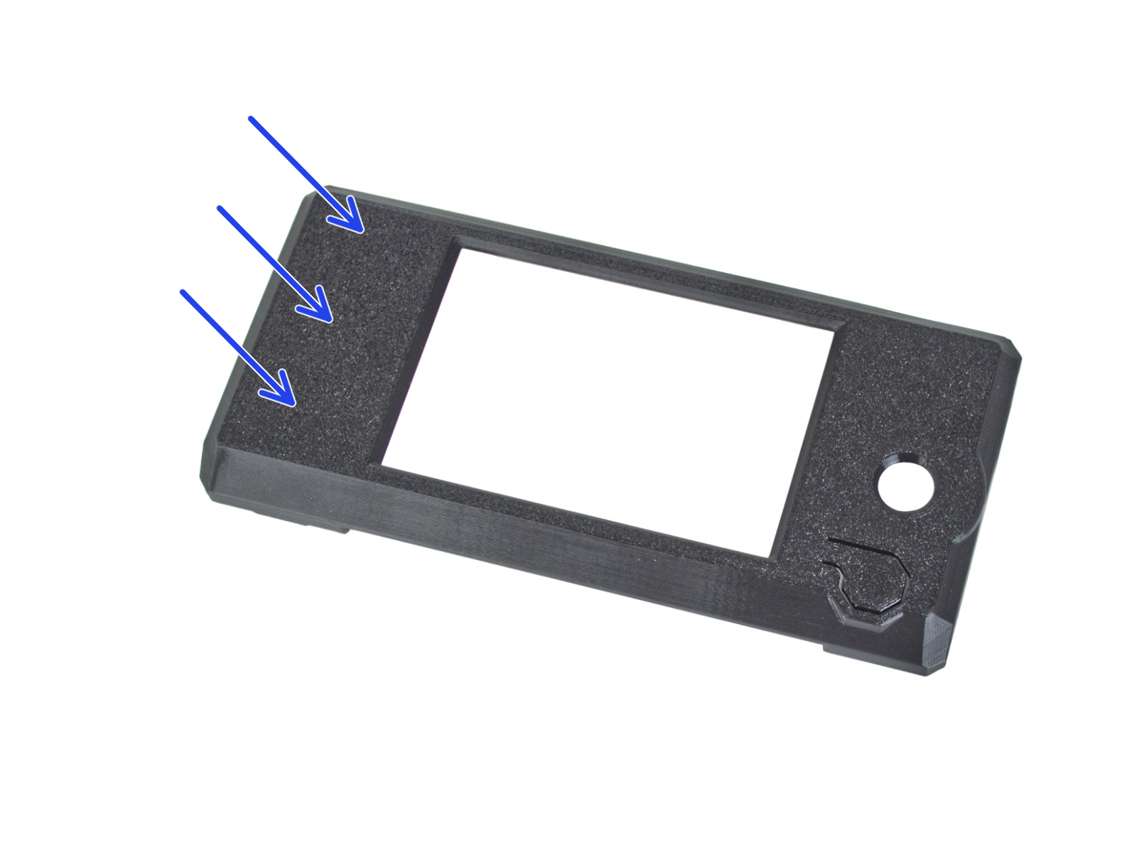
⬢Using the cleaning pad, clean the side without the circle hole on the xLCD-cover.
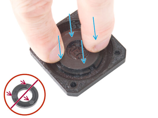
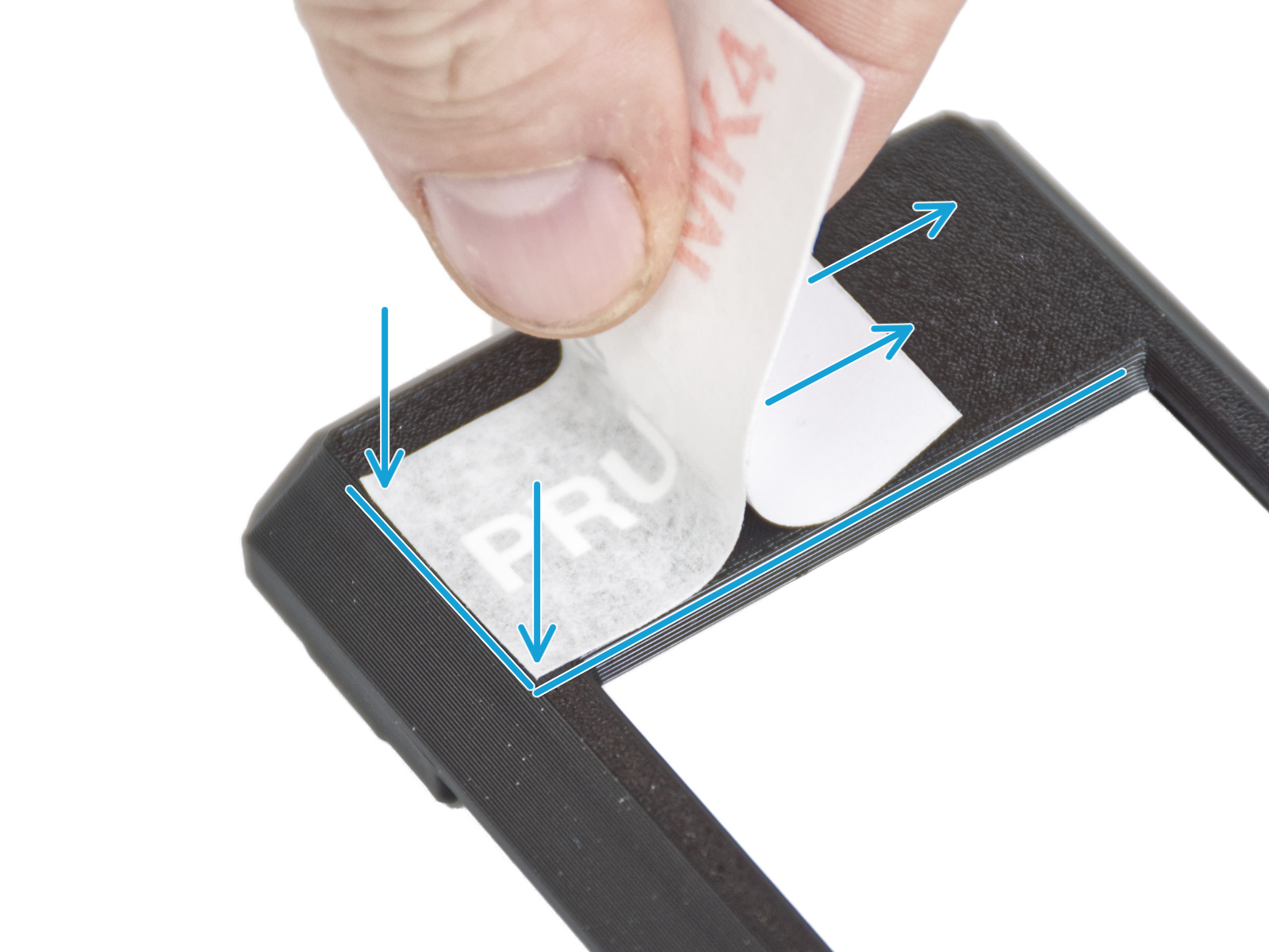
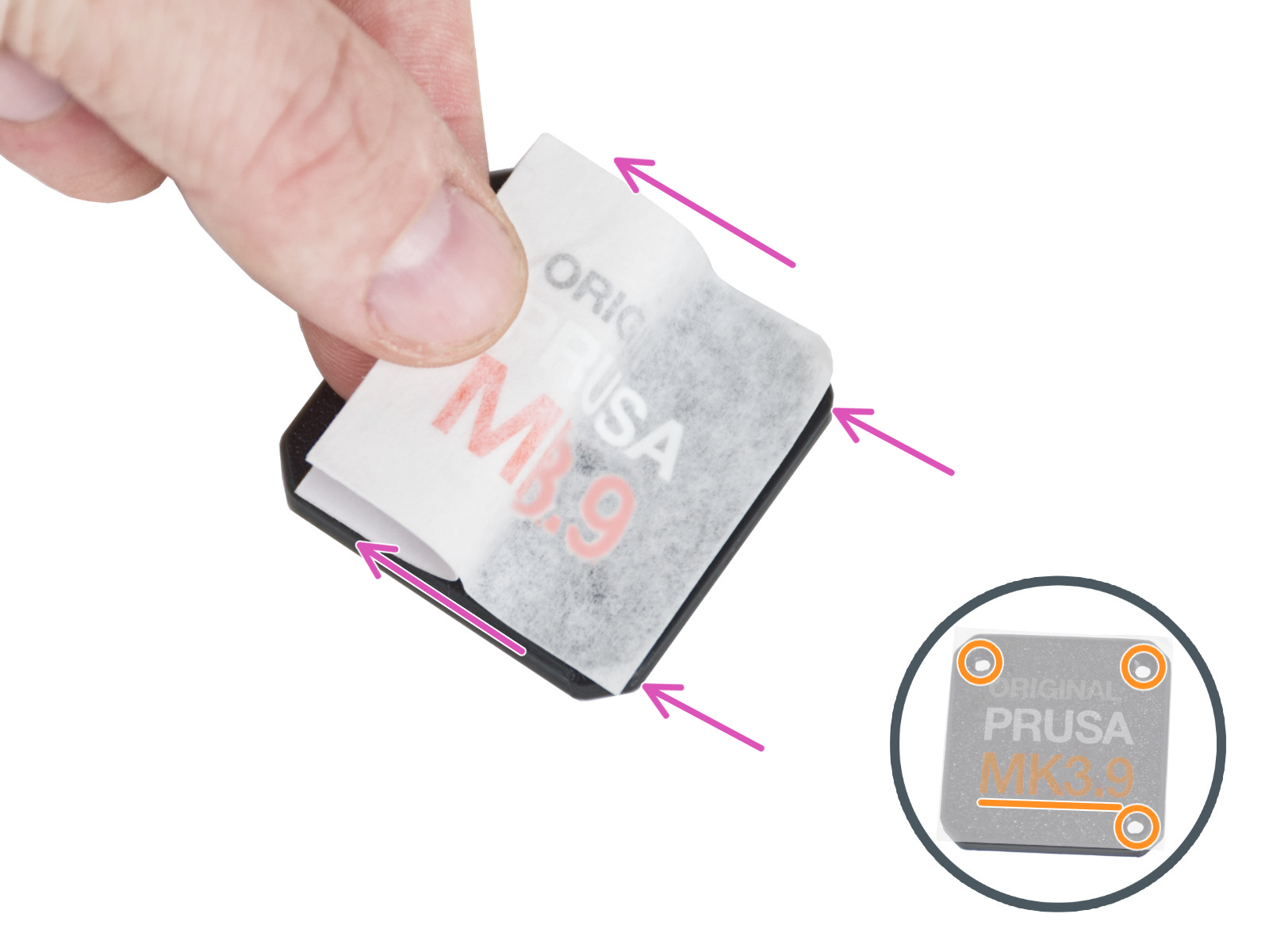
⬢Peel off a piece of the protective layer and carefully glue the sticker on the xLCD-cover. Maintain the sticker aligned with the edges of the display cover. Start on the bottom side.
Notice the white PRUSA lettering through the sticker. Compare the orientation with the second picture.
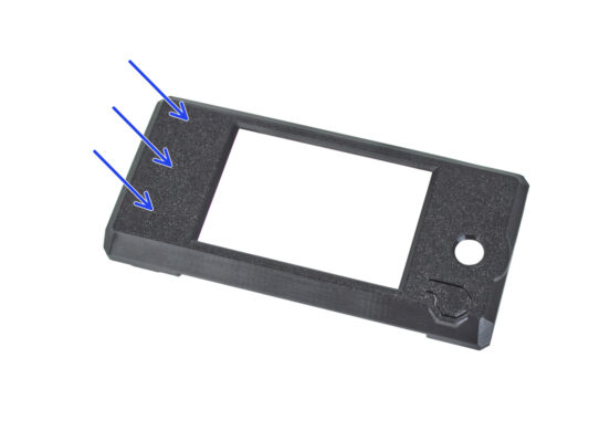
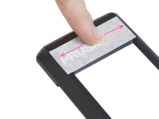
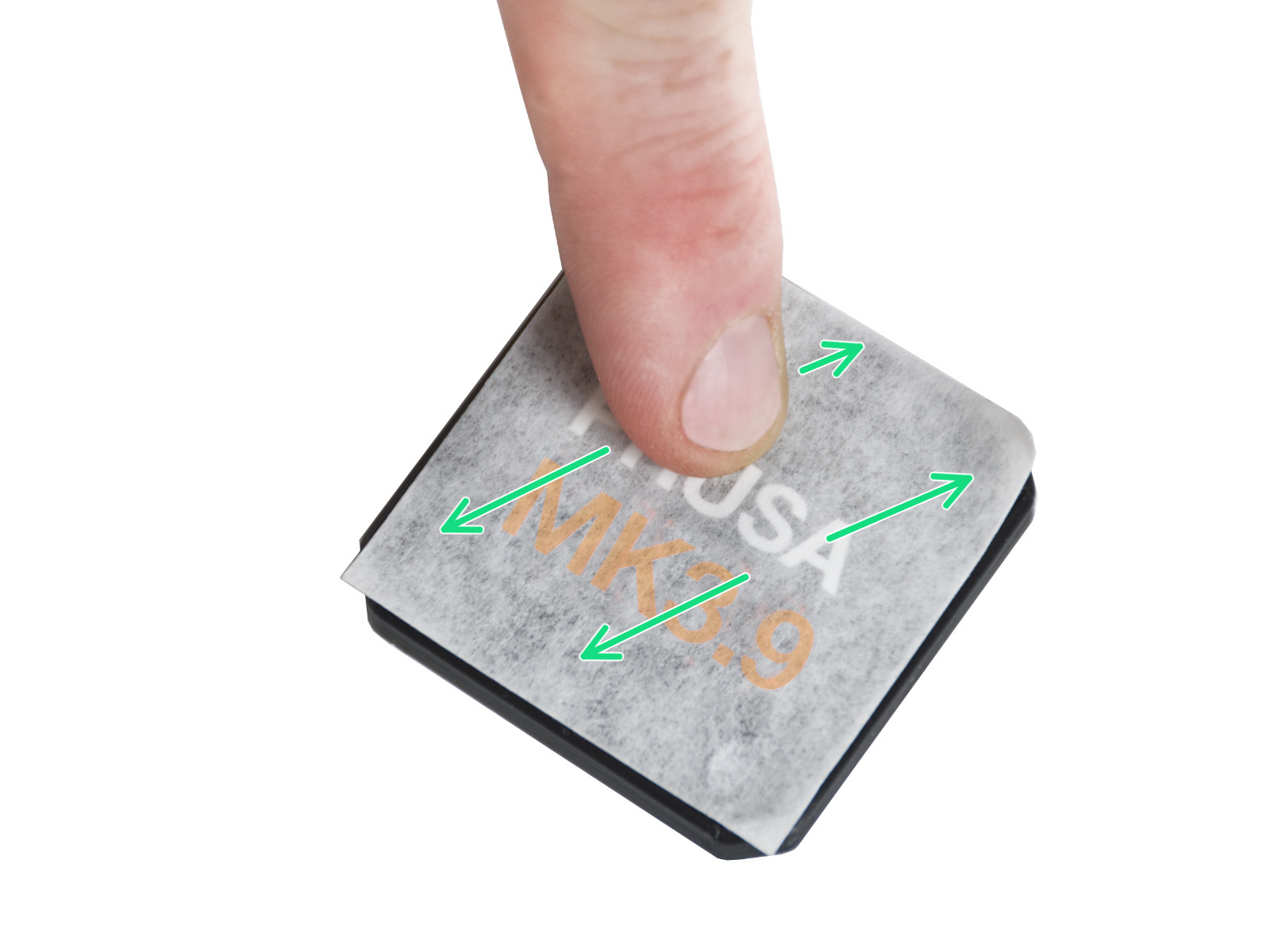
⬢After gluing the sticker, run your finger along the entire length of the sticker in all directions to ensure perfect adhesion.
This process requires patience and care. Perfect adhesion depends on proper degreasing of the part and the ambient temperature.
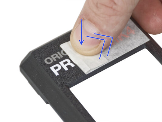
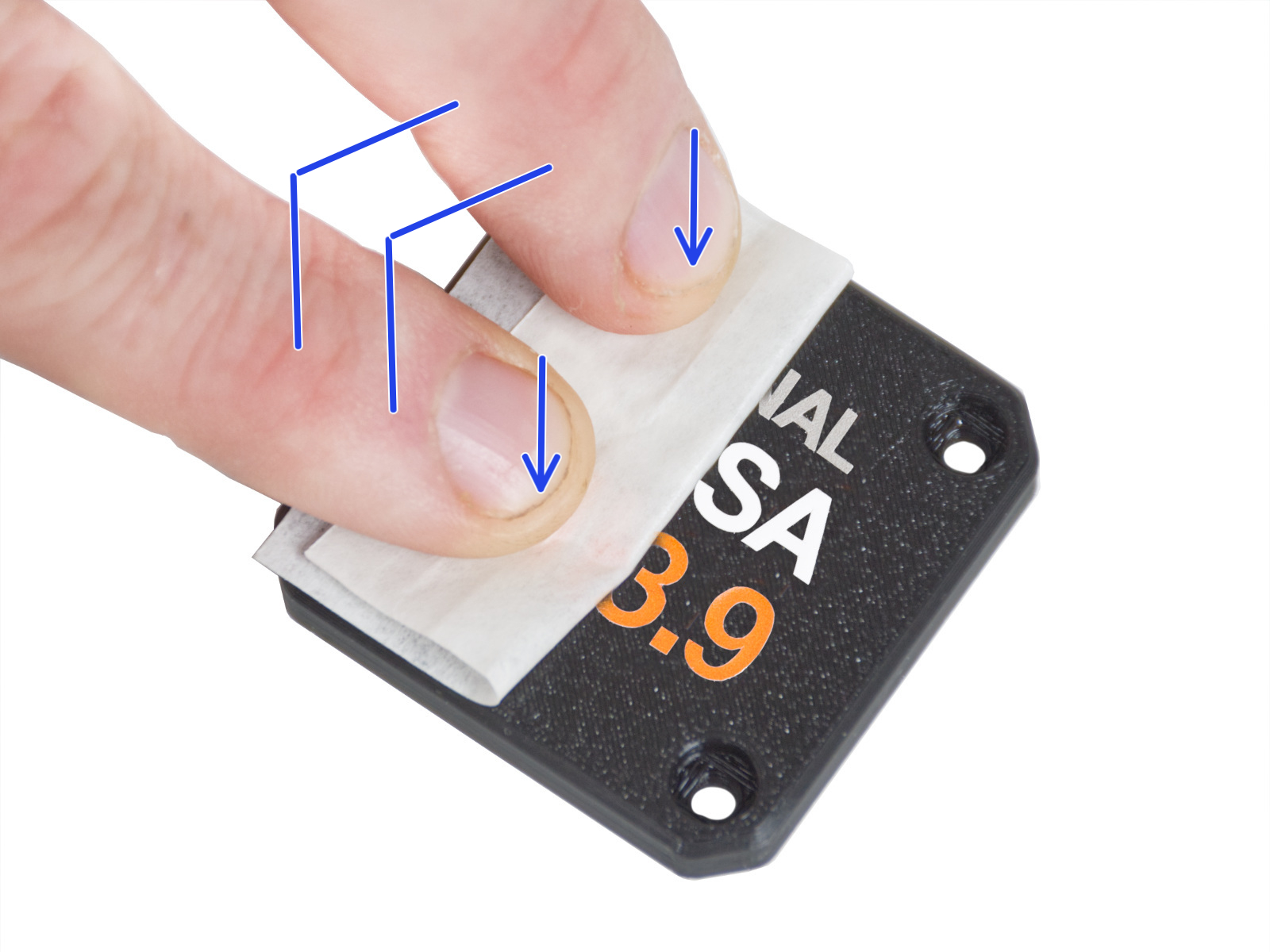
⬢Start slowly peeling off the application layer. Lightly press the layer onto the lettering as you peel it off. Observe whether all the letters are glued on.
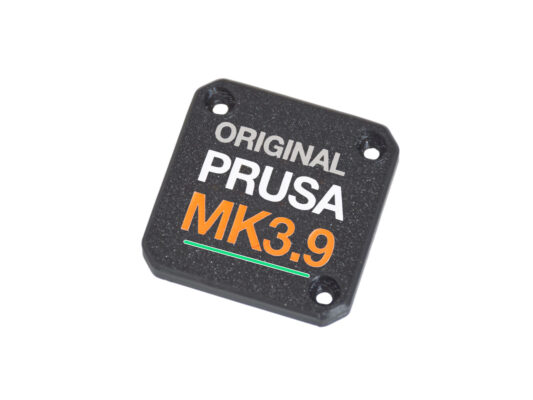
⬢After peeling off the application layer, check that the final look matches the picture.
This process requires patience and care. Perfect adhesion depends on proper degreasing of the part and the ambient temperature.
⬢Start slowly peeling off the application layer. Lightly press the layer onto the lettering as you peel it off. Observe whether all the letters are glued on.
⬢After peeling off the application layer, check that the final look matches the picture.
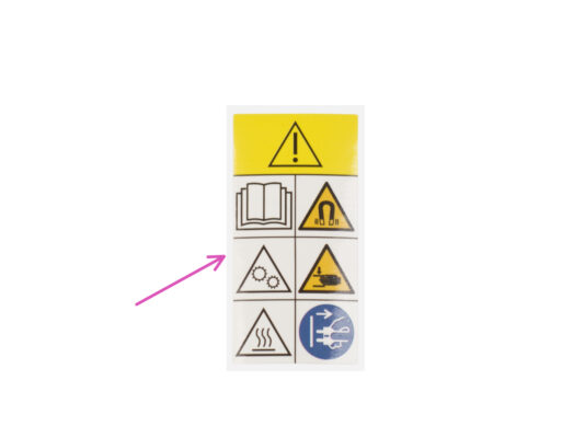
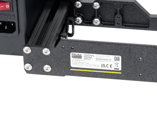
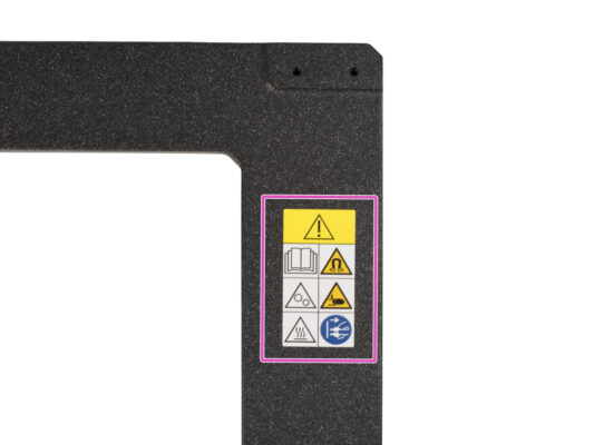
⬢Take a look at the front side of the printer frame. There should be a yellow safety label on the right side of the frame.
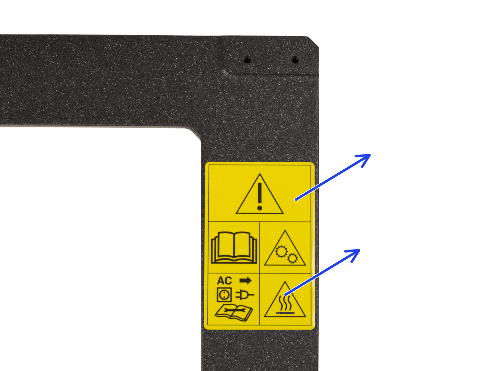
⬢Peel off the label.
⬢Use the supplied cleaning pad to wipe the area where the label was applied.
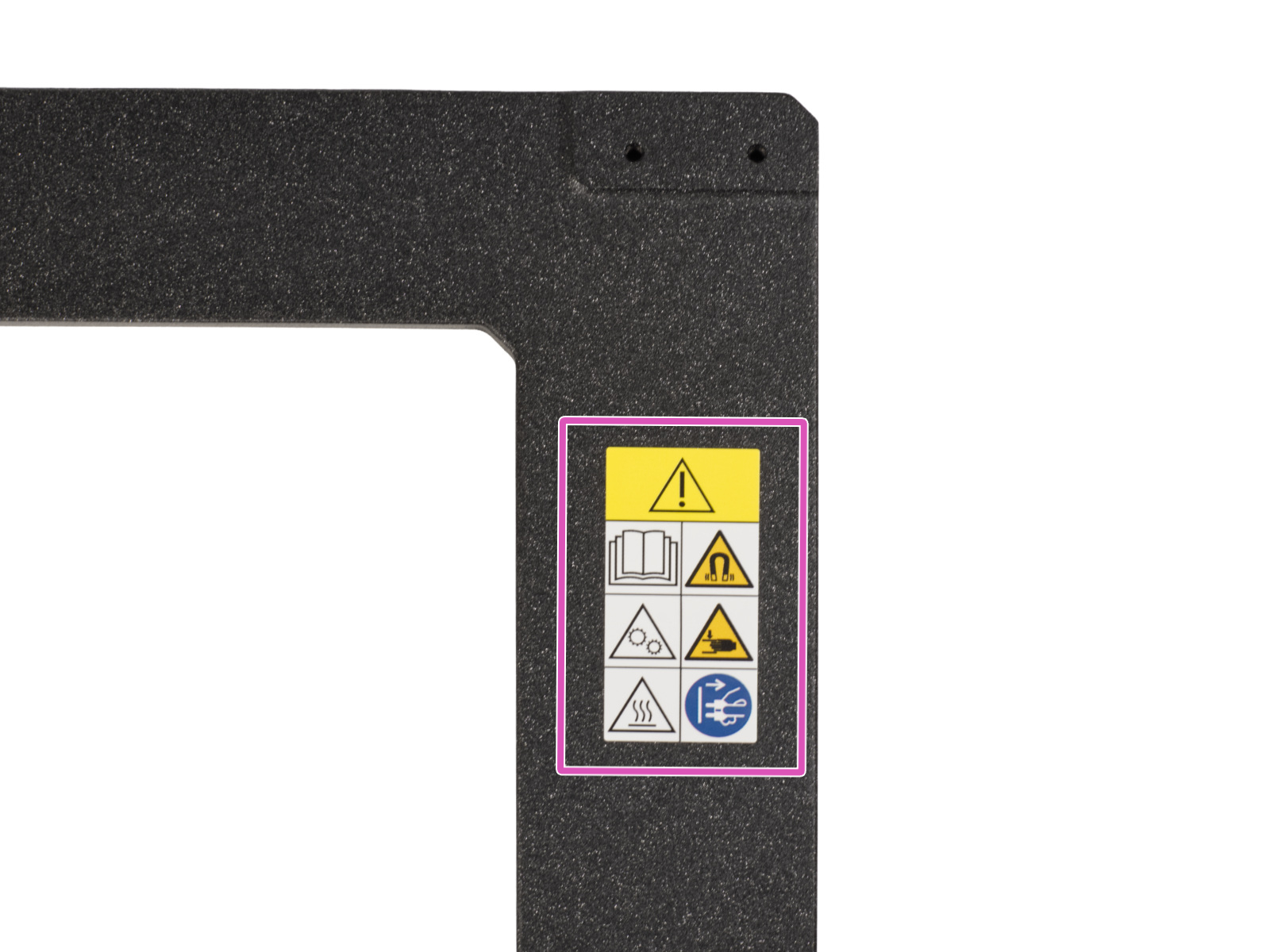
⬢Take a new safety label. Peel off the bottom protective layer from the label and glue the label on the clean surface of the frame.
Please note that the following pictures in the manual were taken with a previous (yellow) version of the safety sticker. This is because they were taken before the new sticker was available.
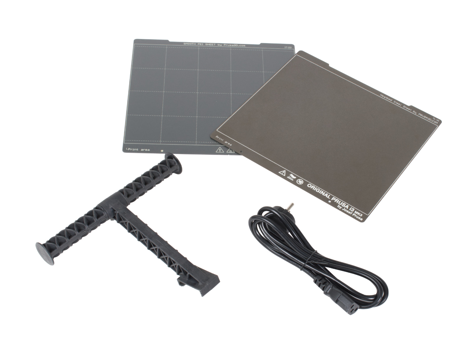
⬢Once you have all of the parts listed, proceed with upgrading your printer.
⬢Enjoy the assembly.
Was this guide helpful?
Comments
Still have questions?
If you have a question about something that isn't covered here, check out our additional resources. And if that doesn't do the trick, you can send an inquiry to [email protected] or through the button below.