- English
- Italiano
- Deutsch
- Polski
- Français
- Home
- Řešení potíží
- Řešení potíží s tiskárnou
- Status LED explained (MMU3)
Status LED explained (MMU3)
- Řešení potíží při tisku
- Řešení potíží s tiskárnou
- A64 Přehřátí #10207 (SL1/SL1S)
- Kontrola okolní teploty (MK3/MK3S)
- Pokojová teplota příliš nízká #10703 (SL1/SL1S)
- Příliš vysoká pokojová teplota #10702 (SL1/SL1S)
- Nastala neočekávaná chyba #10701 (SL1)
- Nelze spustit tuto akci #10506 (SL1/SL1S)
- Alokace BBF selhala #13531 (MK4) #21531 (MK3.9) #23531 (MK3.5)
- BBF Allocation Failed #17531 (XL)
- Inicializace BBF selhala #13532 (MK4) #21532 (MK3.9) #23532 (MK3.5)
- Alokace BBF selhala #17532 (XL)
- Bed maxtemp error #13205 (MK4) #21205 (MK3.9) #23205 (MK3.5)
- Bed mintemp error #13207 (MK4) #21207 (MK3.9) #23207 (MK3.5)
- Chyba předehřevu #13201 (MK4) #21201 (MK3.9) #23201 (MK3.5)
- Bed thermal runaway #13203 (MK4) #21203 (MK3.9) #23203 (MK3.5)
- Spálená pojistka (MINI)
- Prasklá pojistka (MK2S/MK2.5/MK2.5S)
- Spálená pojistka (MK3/MK3S/MK3S+)
- Spálená pojistka (MK4)
- Problém s deskou Boost #10320 (SL1S)
- Zaseknutá tiskárna (SL1/SL1S)
- Kalibrační projekt je neplatný #10543 (SL1/SL1S)
- Nelze zkopírovat projekt #10704 (SL1/SL1S)
- Nelze získat aktualizační kanál #10514 (SL1)
- Nelze načíst projekt #10539 (SL1/SL1S)
- Nelze odebrat projekt #10545 (SL1/SL1S)
- Ucpaná tryska/hotend (MK4)
- Ucpaná tryska/hotend (XL)
- Ucpaná tryska/hotend (MINI/MINI+)
- Ucpaná tryska/hotend (MK3S, MK2.5S)
- Registrace Connectu selhala
- Registrace Connectu selhala #12401 (MINI)
- Registrace Connectu selhala #13401 (MK4)
- Registrace do Connectu selhala #17401 (XL)
- Registrace do Connectu selhala #21401 (MK3.9)
- Registrace do Connectu selhala #23401 (MK3.5)
- Adresář není prázdný #10546 (SL1/SL1S)
- Odpojený UV LED panel #10321 (SL1/SL1S)
- Test displeje selhal #10120 (SL1/SL1S)
- Dwarf error #17502 (XL)
- Dwarf error #17503 (XL)
- EEPROM I2C Receive Busy #13316 (MK4) #21316 (MK3.9) #23316 (MK3.5)
- EEPROM I2C Receive Busy #17316 (XL)
- Nouzové zastavení #12510 (MINI)
- Nouzové zastavení #13510 (MK4) #21510 (MK3.9) #23510 (MK3.5)
- Emergency stop #17510 (XL)
- Chyba ESP #13504 (MK4) #21504 (MK3.9) #23504 (MK3.5)
- Chyba ESP #13505 (MK4) #21505 (MK3.9)
- Chyba ESP #13506 (MK4) #21506 (MK3.9) #23506 (MK3.5)
- ESP error #17504 (XL)
- Chyba ESP #17505 (XL)
- ESP error #17506 (XL)
- Očekávané přehřátí #10714 (SL1/SL1S)
- Externí SPI flash W25X20CL/xFLASH neodpovídá - chyba
- Blob v extruderu
- Extruder Maxtemp error #17206 (XL)
- Chyba extruderu Mintemp #17208 (XL)
- Zvuky z extruderu
- Extruder preheat error #17202 (XL)
- Teplota extruderu neodpovídá #17210 (XL)
- Extruder thermal runaway #17204 (XL)
- Extruze se zastavila uprostřed tisku (heat creep)
- Tovární nastavení (MINI)
- Obnova továrního nastavení (MK2S/MK2.5S/MK3S)
- Factory reset (MK4/XL)
- Factory Reset (MMU)
- Tovární nastavení (MMU2S před firmwarem 1.0.6)
- Tovární nastavení (SL1/SL1S)
- Nelze načíst konfigurační soubor #10505 (SL1)
- Chyba kalibrace osy Z (MK3S/MK2.5S)
- Selhání ventilátoru #10106 (SL1/SL1S)
- Varování ventilátoru #10713 (SL1/SL1S)
- Vysunutí filamentu selhalo (MINI/MINI+)
- Filament nejde zavést
- Filament nejde zavést (MK4)
- Filament nejde zavést (XL)
- Senzor filamentu (MK4, MK3.9, XL)
- Soubor už existuje! #10520 (SL1)
- Soubor nenalezen #10518 (SL1/SL1S)
- Chyba souborového systému #12613 (MINI/MINI+)
- Chyba souborového systému #13613 (MK4) #21613 (MK3.9) #23613 (MK3.5)
- Nastavení FINDA a řešení problémů
- FINDA: Filament Stuck #04102 (MMU)
- Firmware v interní paměti flash je poškozen! #12608 (MINI)
- Firmware missing #17612 (XL)
- Nutná aktualizace firmwaru #13701 (MK4) #21701 (MK3.9) #23701 (MK3.5)
- Problémy s aktualizací firmwaru (MK2S/MK3S/MMU2S)
- Nedrží první vrstva (SL1/SL1S)
- Chyba při mazání flash paměti #12605 (MINI/MINI+)
- Chyba při mazání flash paměti #13605 (MK4) #21605 (MK3.9) #23605 (MK3.5)
- Flash erase error #17605 (XL)
- FW v interní paměti poškozen #13608 (MK4) #21608 (MK3.9) #23608 (MK3.5)
- FW in internal flash corrupted #17608 (XL)
- Hash verifikace selhala #12607 (MINI/MINI+)
- Hash verifikace selhala #13607 (MK4) #21607 (MK3.9)
- Hash verifikace selhala #17607 (XL)
- Vyhřívaná podložka se nezahřívá správně
- Nadproud portu podložky #13309 (MK4) #21309 (MK3.9) #23309 (MK3.5)
- Chyba Heatbreaku MAXTEMP #13212 (MK4) #21212 (MK3.9)
- Chyba heatbreaku maxtemp #17212 (XL)
- Chyba Heatbreaku MINTEMP #13211 (MK4) #21211 (MK3.9)
- Chyba Heatbreaku Mintemp #17211 (XL)
- Homing Error #12301 (MINI)
- Chyba homingu X #13304 (MK4) #21304 (MK3.9) #23304 (MK3.5)
- Homing error X #17304 (XL)
- Chyba homingu Y #13305 (MK4) #21305 (MK3.9) #23305 (MK3.5)
- Homing error Y #17305 (XL)
- Homing error Z #13301 (MK4) #21301 (MK3.9)
- Homing error Z #17301 (XL)
- Chyba homingu Z #23301 (MK3.5)
- Ventilátor hotendu se netočí
- Chyba Hotendu maxtemp #23206 (MK3.5)
- Chyba Hotendu mintemp #13208 (MK4) #21208 (MK3.9)
- Chyba Hotendu mintemp #23208 (MK3.5)
- Chyba předehřevu hotendu #13202 (MK4) #21202 (MK3.9)
- Hotend preheat error #23202 (MK3.5)
- Teplota hotendu neodpovídá #23210 (MK3.5)
- Hotend thermal runaway #13204 (MK4) #21204 (MK3.9)
- Hotend thermal runaway #23204 (MK3.5)
- I2C Receive Failed #13315 (MK4) #21315 (MK3.9) #23315 (MK3.5)
- I2C Receive failed #17315 (XL)
- I2C Receive Timeout #13317 (MK4) #21317 (MK3.9) #23317 (MK3.5)
- I2C Receive Timeout #17317 (XL)
- I2C Receive undefined #13318 (MK4) #21318 (MK3.9) #23321 (MK3.5)
- I2C Receive undefined #17318 (XL)
- I2C odeslání obsazeno #13312 (MK4) #21312 (MK3.9) #23312 (MK3.5)
- I2C Send Busy #17312 (XL)
- I2C Send failed #13311 (MK4) #21311 (MK3.9) #23311 (MK3.5)
- I2C odeslání selhalo #17311 (XL)
- I2C odeslání - časový limit #13313 (MK4) #21313 (MK3.9) #23313 (MK3.5)
- I2C Send Timeout #17313 (XL)
- I2C Send Undefined #13314 (MK4) #21314 (MK3.9) #23314 (MK3.5)
- I2C Send Undefined #17314 (XL)
- Podvod! Falešný podpis #17606 (XL)
- Nesprávný model tiskárny #10705 (SL1/SL1S)
- Interní paměť je plná #10516 (SL1/SL1S)
- Neplatný API klíč #10405 (SL1/SL1S)
- Invalid FW size on USB #12603 (MINI/MINI+)
- Neplatná velikost FW na USB #13603 (MK4) #21603 (MK3.9) #23603 (MK3.5)
- Invalid FW size on USB flash drive #17603 (XL)
- Kalibrace IR senzoru filamentu (MMU2S)
- Řešení problémů se senzorem filamentu (MINI/MINI+)
- Řešení problémů s IR senzorem filamentu (MK2.5S,MK3S)
- Nefunkční LCD obrazovka
- Chyba paměti LED #13529 (MK4) #21529 (MK3.9) #23529 (MK3.5)
- LED Memory Error #17529 (XL)
- Doladění osy Z se neukládá
- Zavedení do extruderu selhalo #04108 (MMU)
- Špatná konfigurace loadcell #13527 (MK4) #21527 (MK3.9)
- Loadcell Bad Configuration #17527 (XL)
- Měření Loadcellu selhalo #13526 (MK4) #21526 (MK3.9)
- Měření loadcellu selhalo #17526 (XL)
- Loadcell není zkalibrován #13523 (MK4) #21523 (MK3.9)
- Loadcell not calibrated #17523 (XL)
- Chyba tárování loadcellu #13524 (MK4) #21524 (MK3.9)
- Loadcell tare error #17524 (XL)
- Loadcell Tare Failed #13525 (MK4) #21525 (MK3.9)
- Loadcell tárování selhalo #17525 (XL)
- Loadcell Timeout #13528 (MK4) #21528 (MK3.9)
- Vypršel časový limit pro loadcell #17528 (XL)
- Logging data over serial line (MMU2S)
- Hlasité zvuky z tiskárny (SL1/SL1S)
- Testování senzorů M.I.N.D.A./SuperPINDA (MINI/MINI+)
- Časový limit požadavku na Marlin #13530 (MK4) #21530 (MK3.9) #23530 (MK3.5)
- Časový limit požadavku na Marlin #17530 (XL)
- Varování: maska není k dispozici #10709 (SL1/SL1S)
- Maxtemp error bed (přehřátí podložky) #12205 (MINI)
- Maxtemp error print head (přehřátí tiskové hlavy) #12206 (MINI)
- Chyba MCU Maxtemp #17213 (XL)
- Mintemp error bed (ochlazení podložky) #12207 (MINI)
- Mintemp error print head (ochlazení tiskové hlavy) #12208 (MINI)
- Špatně usazený senzor PINDA (MK2/S)
- Chybějící části (SL1/SL1S)
- MK3S neustále vyžaduje výměnu filamentu
- MMU MCU nedostatečné napájení #04307 (MMU)
- MMU Overcurrent #13310 (MK4) #21310 (MK3.9) #23310 (MK3.5)
- Idler MMU2S se nemůže volně pohybovat
- Co znamenají LED u MMU2S
- Selektor MMU2S se nepohybuje
- Modular bed error #17250 (XL)
- Modular bed error #17251 (XL)
- Modular bed error #17252 (XL)
- Modular bed error #17253 (XL)
- Chyba modulárního bedu #17254 (XL)
- Chyba modulárního bedu #17255 (XL)
- Chyba modulárního bedu #17256 (XL)
- Chyba modulárního bedu #17257 (XL)
- Modular bed error #17302 (XL)
- Modular bed error #17303 (XL)
- Modular Bed Error #17319 (XL)
- Modular Bed Error #17320 (XL)
- Modular bed error #17501 (XL)
- Použití multimetru
- Žádný soubor na USB #12604 (MINI/MINI+)
- Neexistuje soubor k opětovnému tisku #10508 (SL1)
- Žádný firmware na interní paměti flash #12612 (MINI/MINI+)
- Žádný firmware na interní paměti flash #13612 (MK4) #21612 (MK3.9)
- Na USB není firmware #13604 (MK4) #21604 (MK3.9) #23604 (MK3.5)
- No FW on USB flash drive #17604 (XL)
- Síť odpojena #10402 (SL1/SL1S)
- Nedostatek vrstev #10540 (SL1/SL1S)
- Nedostatek pryskyřice #10706 (SL1/SL1S)
- Čištění trysky selhalo (XL)
- Tryska narazila do vyhřívané podložky
- Nadproud výhřevu trysky #13308 (MK4) #21308 (MK3.9)
- Nadproud výhřevu trysky #23308 (MK3.5)
- Varování: objekt oříznut #10710 (SL1/SL1S)
- Otevírání projektu selhalo #10504 (SL1/SL1S)
- Nedostatek paměti #13507 (MK4) #21507 (MK3.9) #23507 (MK3.5)
- Nedostatek paměti #17507 (XL)
- Testování sondy P.I.N.D.A./SuperPINDA
- Parametry mimo rozsah #10707 (SL1/SL1S)
- Pin not reached #17107 (XL)
- Vyrovnávací paměť PNG je plná #13508 (MK4) #21508 (MK3.9) #23508 (MK3.5)
- Vyrovnávací paměť PNG je plná #17508 (XL)
- Chyba předehřevu #12201 (MINI)
- Chyba předehřevu tiskové hlavy #12202 (MINI)
- Preload selhal #10503 (SL1/SL1S)
- Chybí ukázkové soubory tisku #10523 (SL1/SL1S)
- Tiskový ventilátor se netočí
- Tiskárnu nejde zapnout nebo se sama vypíná
- Analýza projektu selhala #10542 (SL1/SL1S)
- Projekt je poškozen #10541 (SL1/SL1S)
- Řešení potíží s PrusaLinkem
- Puppy error #17511 (XL)
- Puppy error #17512 (XL)
- Puppy error #17513 (XL)
- Puppy error #17514 (XL)
- Puppy error #17515 (XL)
- Puppy error #17516 (XL)
- Puppy error #17517 (XL)
- Puppy error #17518 (XL)
- Puppy error #17519 (XL)
- Puppy error #17520 (XL)
- Puppy error #17521 (XL)
- Puppy error #17522 (XL)
- Chyba Remote API #10407 (SL1/SL1S)
- Nízká hladina resinu #10712 (SL1/SL1S)
- Měření resinu selhalo #10124 (SL1/SL1S)
- Chyba senzoru pryskyřice #10307 (SL1/SL1S)
- Příliš vysoká hladina resinu #10109 (SL1/SL1S)
- Příliš nízká hladina resinu #10108 (SL1/SL1S)
- Vzorové G-cody
- Ukládání logu (SL1/SL1S)
- Nefunkční SD karta
- SD karty a USB flash disky
- Selftest failed (XL)
- Verifikace podpisu selhala #12606 (MINI/MINI+)
- Verifikace podpisu selhala #13606 (MK4) #21606 (MK3.9) #23606 (MK3.5)
- Mechanismus naklápění SL1
- Špageti monster
- Srovnání pravého úhlu os MINI
- Status LED explained (MK4/XL)
- Status LED explained (MMU3)
- During the regular MMU operation:
- MMU Firmware start:
- Other LED lights on the unit:
- Stuck filament detection #13101 (MK4) #21101 (MK3.9)
- Tangled filament
- Teplota vyhřívané podložky neodpovídá #12209 (MINI/MINI+)
- Teplota tiskové hlavy neodpovídá #12210 (MINI/MINI+)
- Teplota mimo rozsah #10208 (SL1/SL1S)
- Ztráta teploty podložky (thermal runaway) #12203 (MINI)
- Ztráta teploty tiskové hlavy (thermal runaway) #12204 (MINI)
- Zkrat TMC driveru #04304 (MMU)
- TMC driver shorted #04314 (MMU)
- Zkrat TMC driveru #04324 (MMU)
- Tool offset out of bounds #17104 (XL)
- Toolchanger error #17101 (XL)
- Kontrola věže selhala #10118 (SL1/SL1S)
- Neoprávněné #10406 (SL1/SL1S)
- Neočekávaná chyba #10501 (SL1/SL1S)
- Neočekávaná chyba MC #10306 (SL1/SL1S)
- Neznámý model tiskárny #10323 (SL1/SL1S)
- Nepodporovaná verze BBF #12614 (MINI/MINI+)
- Nepodporovaná verze BBF #13614 (MK4) #21614 (MK3.9) #23614 (MK3.5)
- Unsupported Buddy FW #17611 (XL)
- Unsupported firmware BBF file #17614 (XL)
- Unsupported printer model #17610 (XL)
- Nepodporovaný model tiskárny #12610 (MINI/MINI+)
- Nepodporovaný model tiskárny #13610 (MK4) #21610 (MK3.9) #23610 (MK3.5)
- Nepodporovaná verze tiskárny #12611 (MINI/MINI+)
- Nepodporovaná verze tiskárny #13611 (MK4) #21611 (MK3.9) #23611 (MK3.5)
- Přepetí na USB zařízení #13307 (MK4) #21307 (MK3.9) #23307 (MK3.5)
- Na portu USB zjištěn nadproud #17307 (XL)
- USB disk nenalezen #10528 (SL1/SL1S)
- USB flash drive not connected #17602 (XL)
- USB flash error #17613 (XL)
- USB not connected #12602 (MINI/MINI+)
- USB není připojeno #13602 (MK4) #21602 (MK3.9) #23602 (MK3.5)
- Nadproud na USB portu #13306 (MK4) #21306 (MK3.9) #23306 (MK3.5)
- USB Port Overcurrent #17306 (XL)
- Chyba teploty UV LED světla #10209 (SL1/SL1S)
- Chyba napětí UV LED #10309 (SL1)
- Vibrace během tisku (MK3S+/MK2.5S)
- Nesprávný model tiskárny #10544 (SL1/SL1S)
- Chybná revize pohybového ovladače #10301 (SL1)
- XY position invalid #17106 (XL)
- XY probe unstable #17105 (XL)
- Chybové QR kódy
- Chybová hlášení při tisku
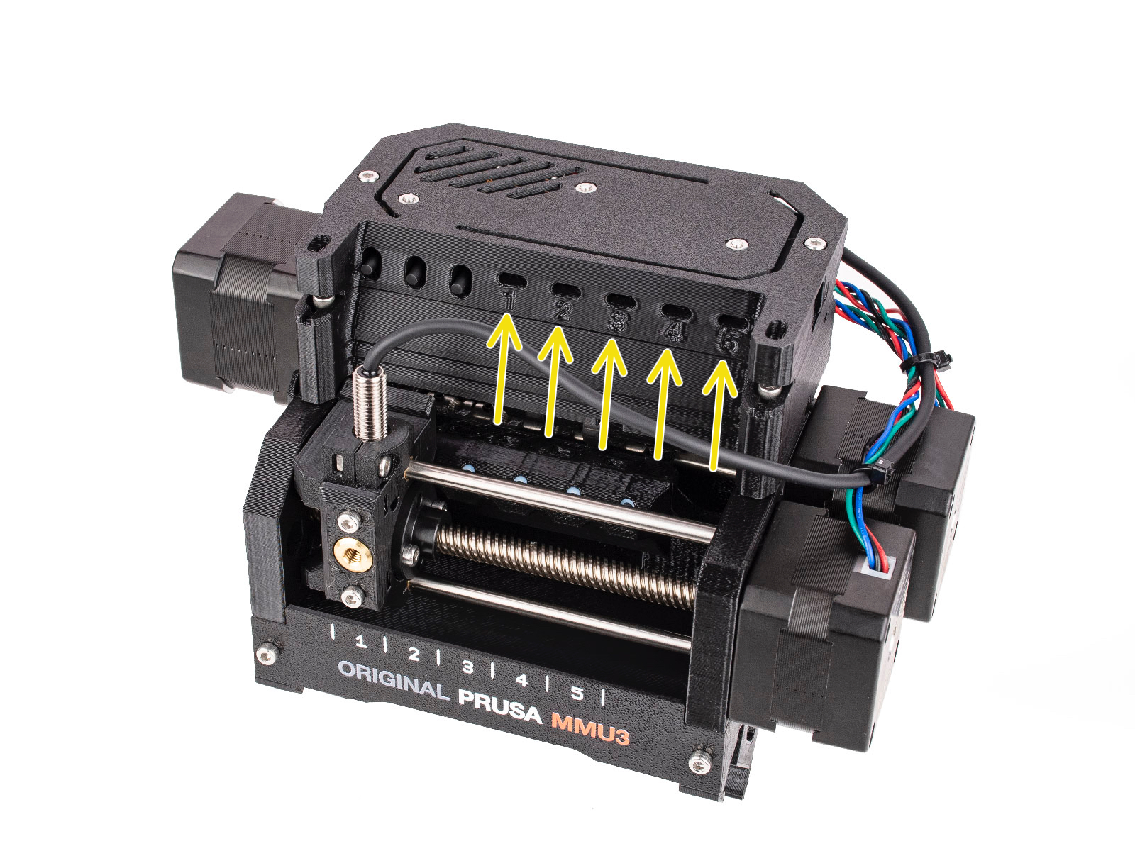
This article is describing the status of the LEDs located on the multi material unit. Together there are five LEDs on the unit that correspond to the five available filament positions.
Note that the earlier MMU2S firmware 1.0.6 or below behaves differently.
During the regular MMU operation:
- GREEN solid light: The MMU has a record of the given filament being loaded in the extruder.
- GREEN flashing light: There is a loading/unloading process going on.
- RED flashing light: There is a loading/unloading error with the given filament. The unit is waiting for user interaction.
- RED and GREEN flashing lights: Internal runtime error, refer to the error shown on the printer’s LCD.
MMU Firmware start:
After the MMU unit has been turned on or restarted, green LEDs light up from positions 5 to 1 shortly (~100ms). Each signalizes one component up and running:
- LED 5: Shift registers initialization
- LED 4: USART initialization
- LED 3: SPI communication initialization
- LED 2: motion system initialization
- LED 1: ADC initialization
If the MMU stops in this setup phase (the LEDs stay on and do not turn off), something is wrong with the electronics.
Then, a selftest routine is performed. It checks if the main control board behaves correctly and if all the signals from the microcontroller get to the TMC motor drivers on the control board properly. If the MMU unit suspects the communication with any of the three TMC motor drivers might not behave correctly, an error is shown. In that case, refer to the printer’s LCD screen.
LED lights indicate the ongoing phases of the selftest routine:
- LED 1: ok (green) / error (red) on STEP signal
- LED 2: ok (green) / error (red) on DIR signal
- LED 3: ok (green) / error (red) on ENABLE signal
- LED 4 indicates which TMC driver is being tested
- Idler = green
- Selector = red
- Pulley = green+red
- LED 5 is flashing green while the process is still ongoing.
Other LED lights on the unit:
There are also other less important LED indicators on the unit.
- A green LED on the MMU3 PD-board addon, on the back of the unit. It signalizes the board receiving power from the printer.
- An orange indicator "breathing" on the inside of the MMU unit, on the main control board, signalizes the electronics booting up.
- A red indicator on the top of the FINDA sensor signalizes the sensor being powered up and NOT detecting a filament.
Komentáře


Stále nemáte jasno?
Pokud nemůžete najít odpověď na vaši otázku, projděte si naše další materiály na webu.
A pokud nenajdete odpověď, pošlete nám zprávu na [email protected] nebo přes tlačítko níže.