English
Login
3D printers
Materials
Parts & Accessories
For Business
Software
3D Models
Community
Help
Courses
Blog
Company
Support
Original Prusa XL
Printer maintenance
How to replace a Nextruder (XL single-tool) | Begin assembly
1. Begin assembly
Step 1 of 21 (Chapter 42 of 42)
Contents
Comments
Difficulty
Moderate
Available languages
Begin assembly
Download guide as PDF
Contents
Printer maintenance
How to replace the CoreXY plastic parts
How to install the Nextruder V6 Nozzle Adapter (XL single-tool)
How to replace the Prusa Nozzle (XL single-tool)
How to replace the Hotend assembly (XL single-tool)
Packing printer for transport - Original Packing Material (XL)
How to replace the Prusa Nozzle (XL multi-tool)
How to replace a Z-axis motor (XL)
Packing the XL Multi-tool for return - Original Packing material
How to replace a heatbed tile and a heatbed tile cable (XL)
How to replace a print fan (XL single tool)
How to fix Modular bed error (HW solution)
How to replace trapezoid nuts (XL)
How to clean the side filament sensor (XL)
How to change xLCD and xLCD cable (XL single-tool)
How to replace a Dwarf board (XL multi-tool)
How to replace Nextruder heatsink (XL Multi-tool)
How to replace a Dwarf board (XL single-tool)
How to replace the Hotend assembly (XL multi-tool)
How to replace a hotend thermistor (XL Single-Tool)
How to replace a Z-axis linear rail (XL)
How to replace a profile insert (XL)
How to replace the hotend fan (XL Multi-tool)
How to replace a PSU (XL)
How to replace a hotend heater (XL Single-Tool)
How to lubricate the coupler pins on Original Prusa XL (Multi-Tool)
How to replace the tch-profile-insert (XL)
How to replace the Sandwich Board (XL)
How to replace the rubber band on Original Prusa XL (Multi-tool)
How replace the CoreXY Cover Rear (Original Prusa XL)
How to install the Nextruder V6 Nozzle Adapter (XL Multi-Tool)
How to replace a XY motor (XL)
Packing the XL Enclosure for return - Original Packing material
How to change the belt (XL)
How to replace the main cable connector cover (XL)
How to replace the PDU splitter (XL)
How to replace the print fan (XL multi-tool)
How to replace trapezoid nuts (XL)
How to lubricate linear bearing rails (XL)
How to change the xLCD (XL)
How to set up a Buddy3D Cam
How to replace Nextruder heatsink (XL Single-tool)
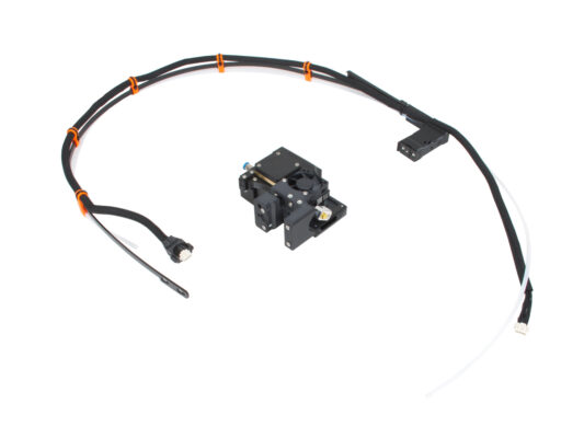
How to replace a Nextruder (XL single-tool)
Begin assembly
Introduction
Tools necessary for this chapter
Preparing the printer
Unpluging the printer
Disconnecting the extruder
Detaching the extruder cable
Extruder detaching
Extruder take off
Preparing the new Nextruder
Nextruder cable & PTFE tube
Nextruder cable bundle assembly
Nextruder cable bundle assembly
Installing the extruder: parts preparation
Installing the extruder
Securing the extruder
Guiding the extruder cable
Attaching the extruder cable
Connecting the extruder cable
Attaching the filament sensor
Well done!
Comments
Log in
to post a comment
No comments