How to replace the CoreXY plastic parts
How to install the Nextruder V6 Nozzle Adapter (XL single-tool)
How to replace the Prusa Nozzle (XL single-tool)
How to replace the Hotend assembly (XL single-tool)
Packing printer for transport - Original Packing Material (XL)
How to replace the Prusa Nozzle (XL multi-tool)
How to replace a Z-axis motor (XL)
Packing the XL Multi-tool for return - Original Packing material
How to replace a heatbed tile and a heatbed tile cable (XL)
How to replace a print fan (XL single tool)
How to fix Modular bed error (HW solution)
How to replace trapezoid nuts (XL)
How to clean the side filament sensor (XL)
How to change xLCD and xLCD cable (XL single-tool)
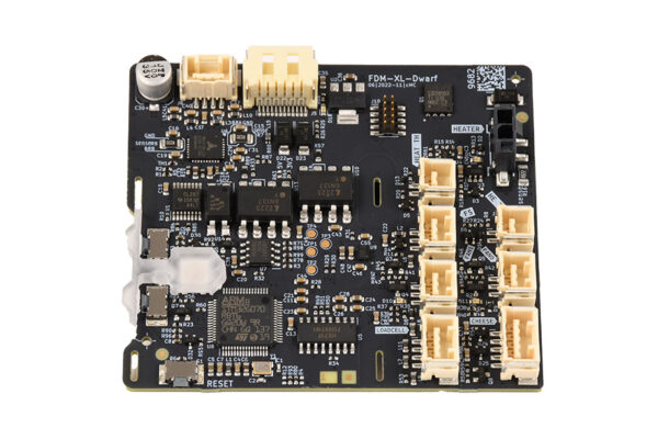
How to replace a Dwarf board (XL multi-tool)
- Begin assembly
- Introduction
- Necessary tools
- Unloading filament
- Preparing the printer
- Protecting the heatbed
- Undocking the Nextruder
- Removing covers
- Nextruder cable bundle disassembly
- Disconnecting cables
- Removing the Dwarf board
- Assembling the new Dwarf board
- Connecting cables
- Connecting cables
- Covering Dwarf board top
- Nextruder cable bundle assembly
- Re-assembling covers
- Docking the Nextruder
- Final check
- It's done
How to replace Nextruder heatsink (XL Multi-tool)
How to replace a Dwarf board (XL single-tool)
How to replace the Hotend assembly (XL multi-tool)
How to replace a hotend thermistor (XL Single-Tool)
How to replace a Z-axis linear rail (XL)
How to replace a profile insert (XL)
How to replace the hotend fan (XL Multi-tool)
How to replace a PSU (XL)
How to replace a hotend heater (XL Single-Tool)
How to lubricate the coupler pins on Original Prusa XL (Multi-Tool)
How to replace the tch-profile-insert (XL)
How to replace the Sandwich Board (XL)
How to replace the rubber band on Original Prusa XL (Multi-tool)
How replace the CoreXY Cover Rear (Original Prusa XL)
How to install the Nextruder V6 Nozzle Adapter (XL Multi-Tool)
How to replace a XY motor (XL)
Packing the XL Enclosure for return - Original Packing material
How to change the belt (XL)
How to replace the main cable connector cover (XL)
How to replace the PDU splitter (XL)
How to replace the print fan (XL multi-tool)
How to replace trapezoid nuts (XL)
How to lubricate linear bearing rails (XL)
How to change the xLCD (XL)
How to set up a Buddy3D Cam
How to replace Nextruder heatsink (XL Single-tool)
How to replace a Nextruder (XL single-tool)