Relevante para


After installing the INDX on your Prusa CORE One/+, the selftest will check the printer's assembly, wiring, and electronic components. It is the first part of the Calibration Wizard, which is prompted automatically when you turn on the printer for the first time or after a factory reset. After the initial calibration is completed, each step of the selftest can be initiated under LCD Menu -> Control -> Calibrations & tests.
Note that if the printer is placed on an unstable surface or if another 3D printer is running next to it, it may negatively affect the calibration. The printer should be placed on a stable surface.
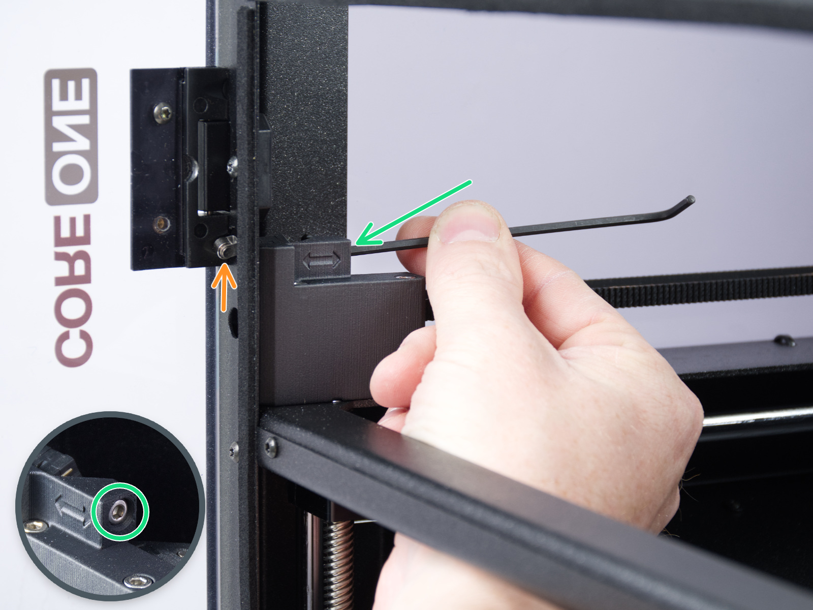
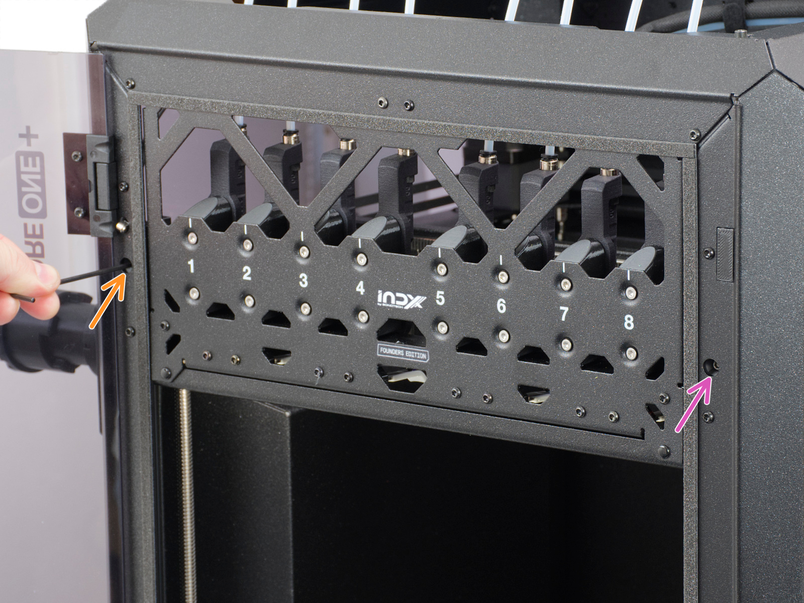
If the sensor behaves differently from what is expected in the door sensor calibration, check whether the sensor is working. Go to the LCD menu to Info -> Sensor Info -> Door Sensor. Then, try opening and closing the door and see if the sensor is triggered. If the door does not trigger the sensor, try it by pressing the latch with your finger.
If the sensor shows the correct status, go back to the calibration by going to Control -> Calibrations & tests -> Door sensor, and follow the instructions to tighten or loosen the screws.
On the last part of the calibration, the printer prompts you to place your fingers between the door and the frame. This is meant to prevent injury. If there is an issue with this test, you can keep the door completely open to pass.
If the door sensor does not work, check the cable for damage and the connection.
This part of the selftest measures the axis length and motor load.
In case of an issue on the X-axis or the Y-axis, make sure that there is no obstacle to the movement, and readjust the belt tension.
Also, test the printer movement with the stepper motors temporarily disabled (LCD Menu -> Control -> Disable Motors), moving along both XY diagonals.
If the issue persists, look through the openings on the plastic parts under the CoreXY motors. You will be able to see the motor pulleys. Make sure that they are in the correct orientation, that both set screws are firmly tightened, and that one of them is tightened over the flat part of the motor shaft.
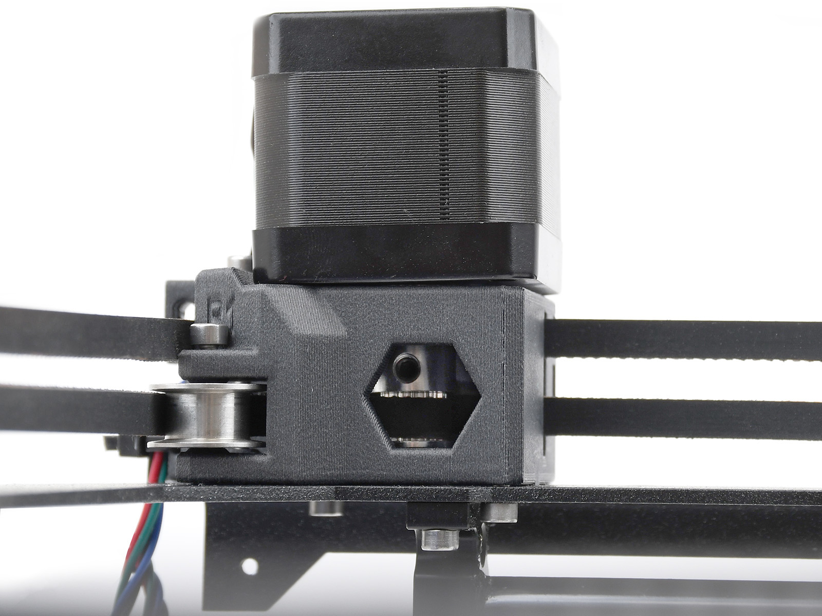 | 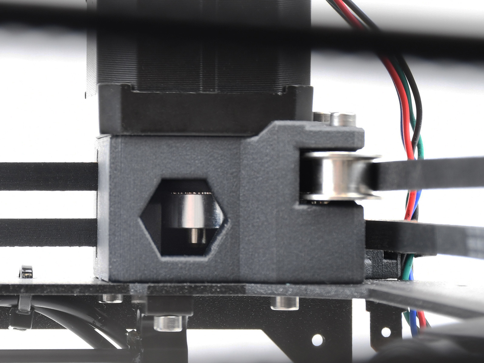 |
| Y-motor pulley | X-motor pulley |
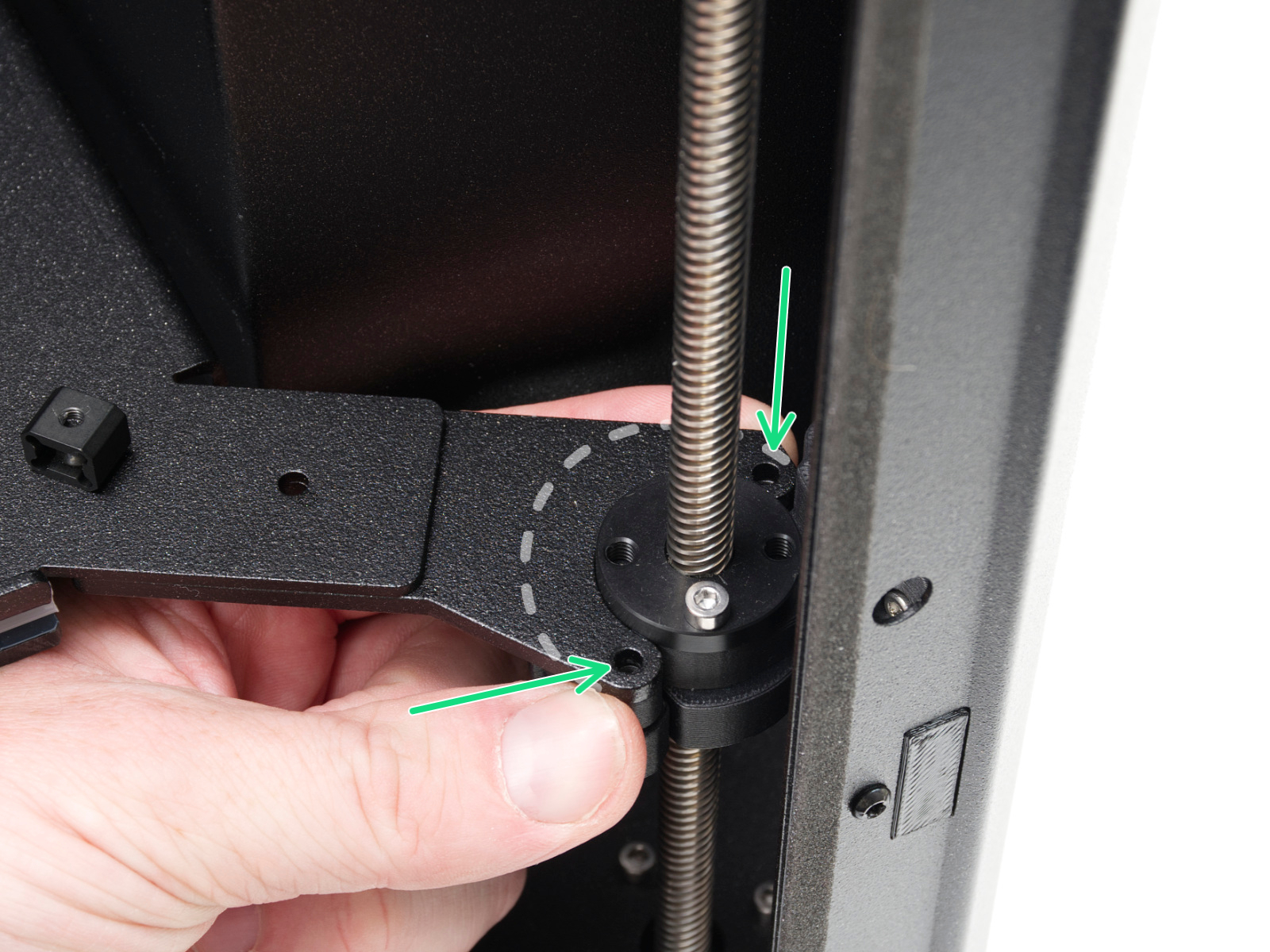
This part of the calibration will move to align the three motors on the Z axis so that the heatbed is level. In case of any errors on this test, check the trapezoidal nuts on the motor threaded rods. For that, move the bed all the way down either by the LCD menu in Control -> Move axis -> Move Z, or by turning the threaded rods on the Z motors. Unscrew and remove the screws indicated in the image below. Move the nut along the threaded rod and see if the movement is smooth or not. When the trapezoid nut is still loose, try moving the motor threaded rod by hand (the printer needs to be powered off for that), and see if it turns easily.
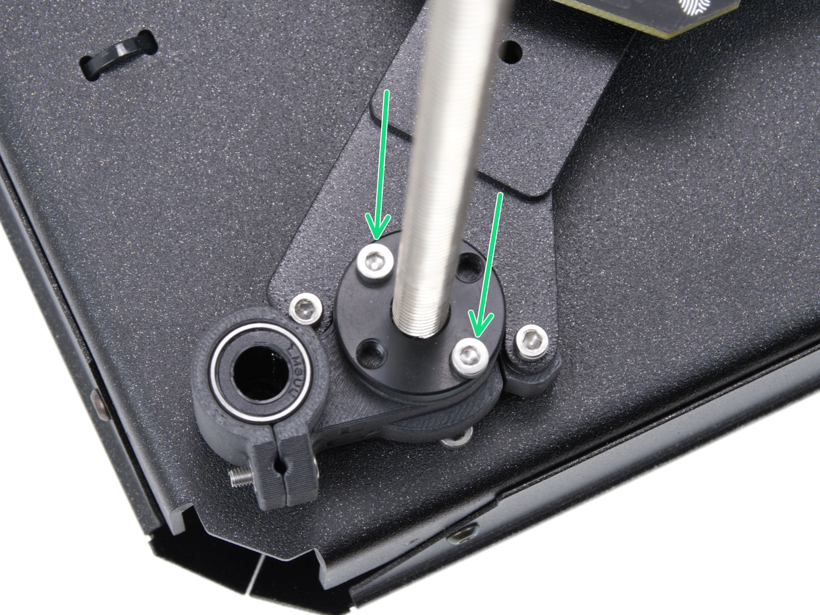 | 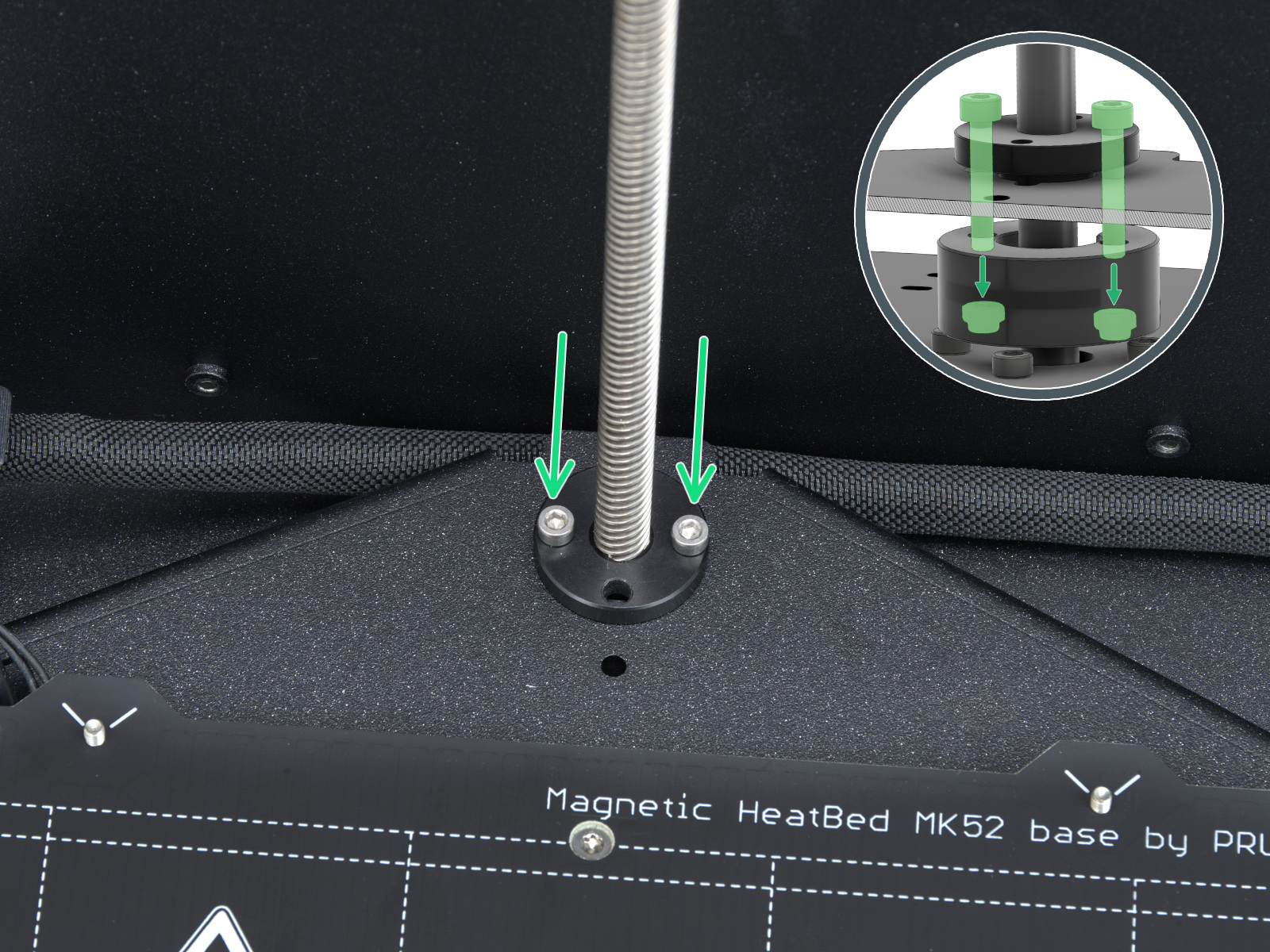 | 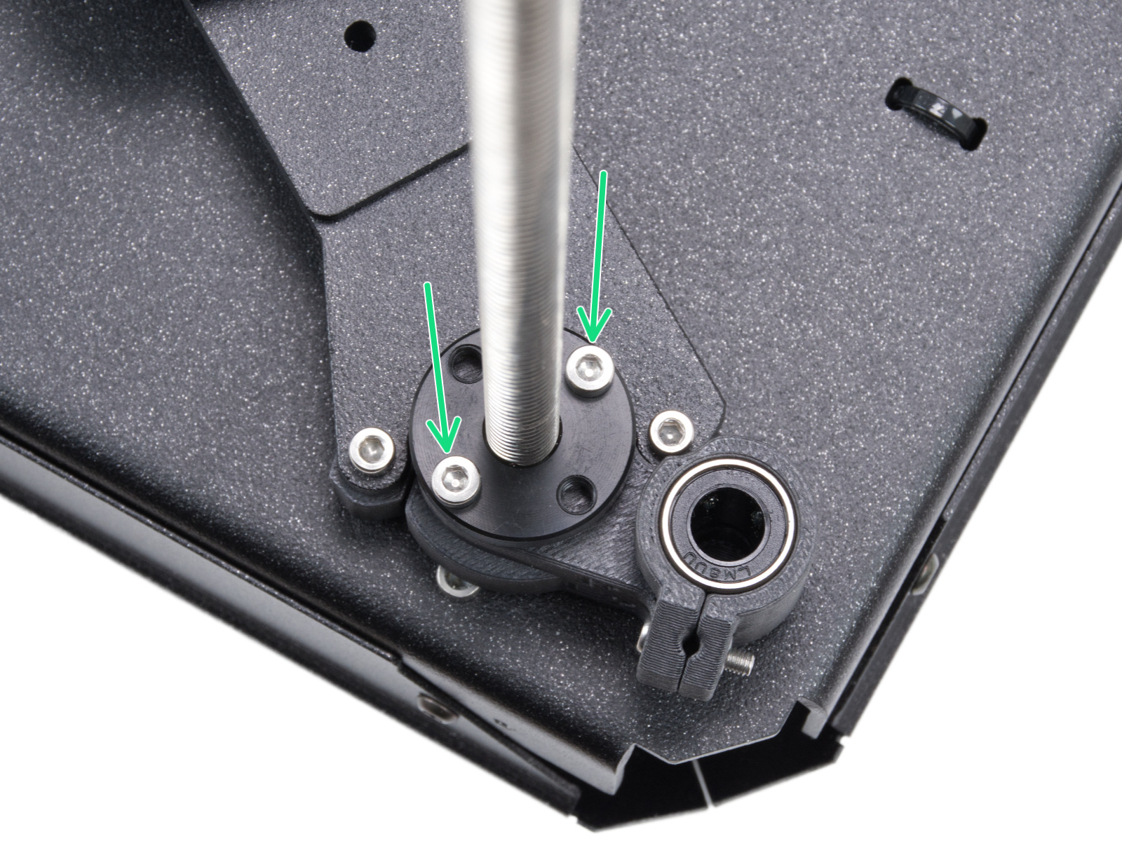 |
| Left side trapezoidal nut | Rear motor trapezoidal nut | Right side trapezoidal nut |
Check also that the spacers are correctly installed.
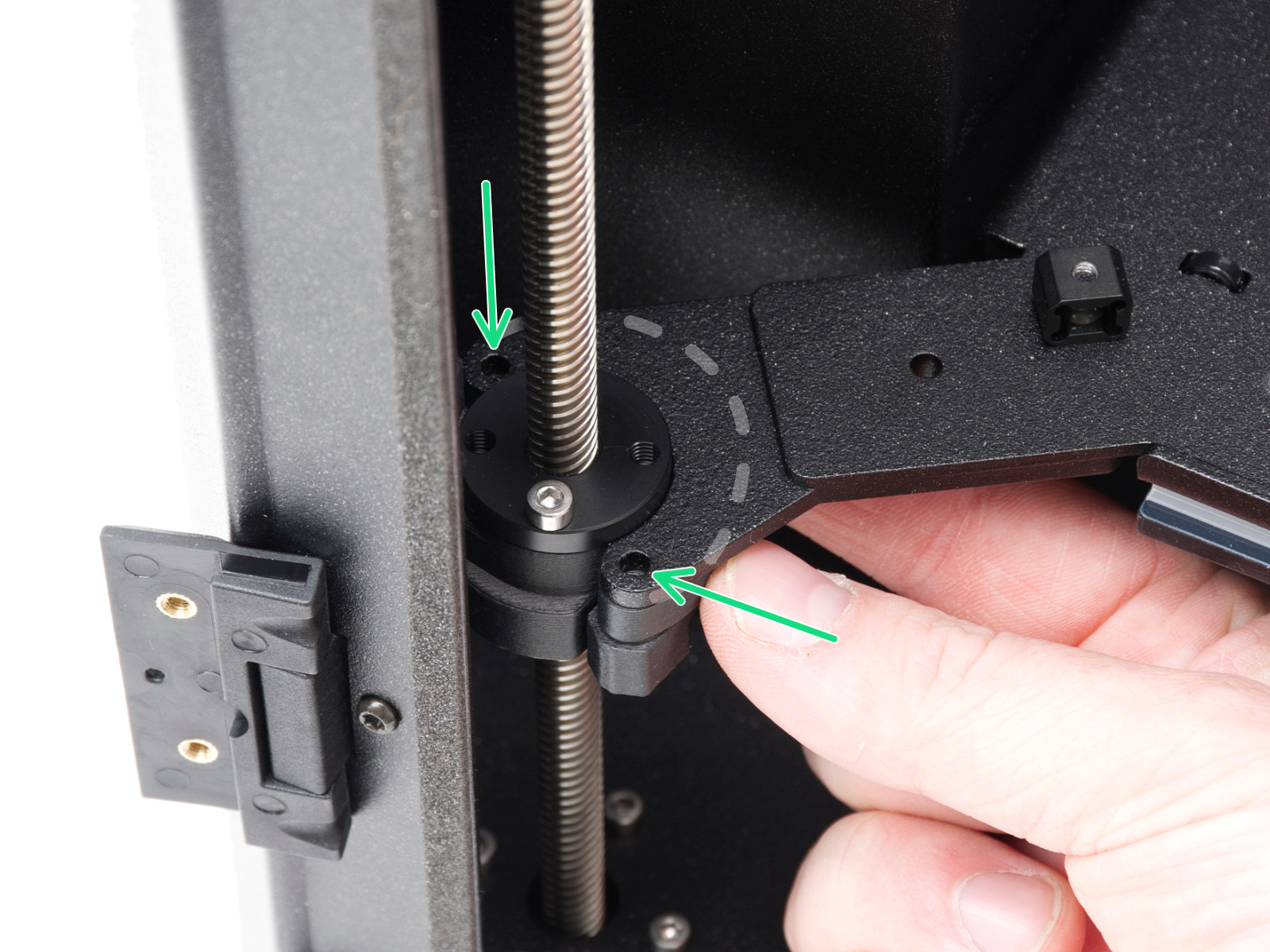 | 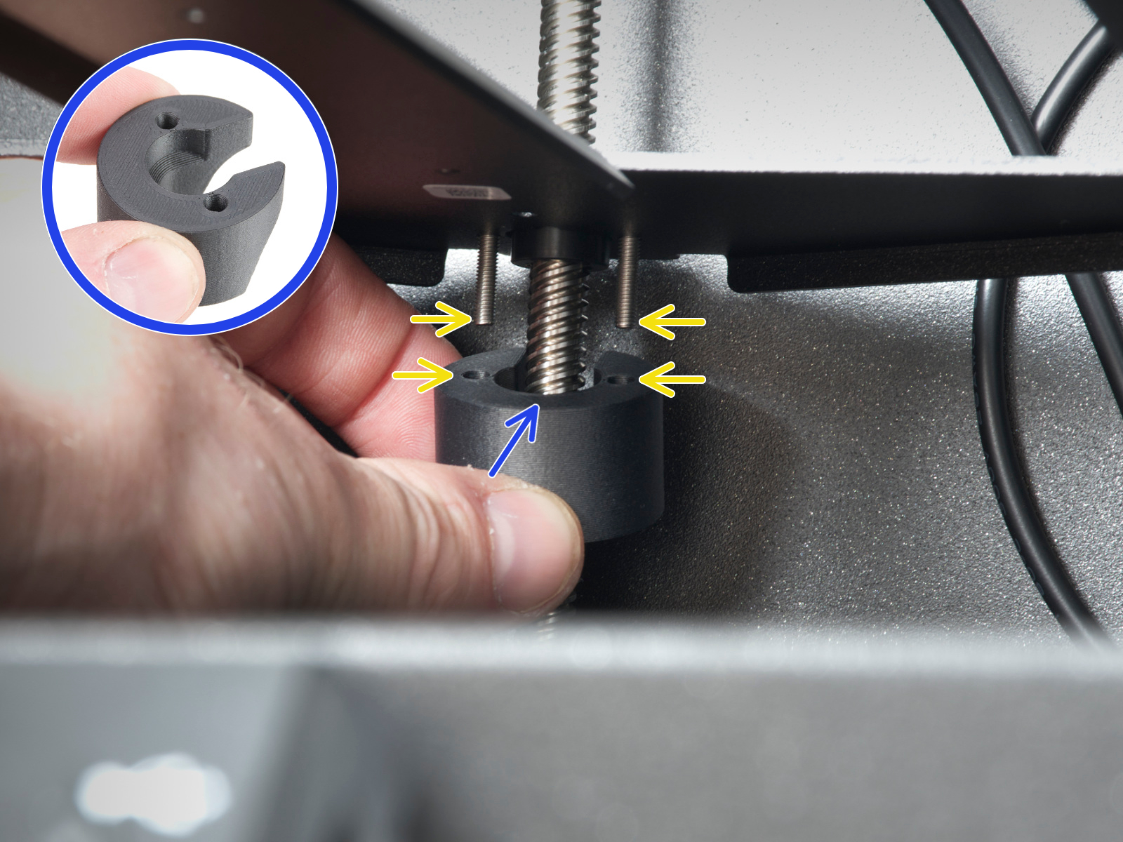 |  |
| Left spacer | Rear spacer | Right spacer |
The LCD menu will guide you through the belt wizard. If one of the sides shows a gap, do the following procedure:
If there are issues with the homing calibration, check the X and Y axes and the homing calibration again.
This calibration will test each dock. If a specific dock fails, try:
A functioning loadcell is fundamental to detect that the nozzle is close enough to the steel sheet for printing, and to avoid damage that would be caused by the nozzle digging into the steel sheet.
Make sure that the surface the printer is on is as stable as possible: any form of vibration propagated to the surface under the printer, or a not fully stable surface under the printer, might cause a false reading on the loadcell, causing it to fail the selftest.
Check also if the main cable is properly connected to the toolchanger.
Check if there is anything blocking the path of the Z axis. It may be something stuck in the threaded rods or anything on the floor of the chamber.
This part will test all fans in the printer. The RPM values for the fans need to be within these values for the test to pass:
If there is an error shown, first define which one of the fans has the issue.
The hotend fan is not accessible. To test it, go into the LCD menu to Control -> Temperature -> Nozzle, and set the nozzle to any temperature above 50 ºC. Check if you can hear the fan spinning. Then, go to the LCD menu in Info - Sensor Info - Fan Info, and check the hotend fan RPM.
If any of the other fans do not pass the test, check:
The selftest can determine a fault during the heating of a component, and the affected component.
Heat the affected component under LCD Menu -> Control -> Temperature, heat up the part that failed the selftest, and see if any error appears. If it does, the error should have a QR code that redirects to the article that describes how to troubleshoot that particular error.
If the tool offset calibration fails, check if all the nozzles are positioned correctly and the nozzle tips are clean.
Then, check the offset sensor for the following:
Also, try to redo the homing calibration.
This calibration is a measurement and should not give any errors. In case the printer can't complete these tests, check the axes again.
The INDX has a side filament sensor. If the calibration fails, check the following:
For this test, make sure that you are not touching the printer and that no other printers are running on the same surface as the CORE One INDX. You can read more about it here: Phase Stepping (CORE One).
After this calibration, the printer will show you the Input shaper frequency values. The lower limit is 35 Hz, and the upper limit is 70 Hz. If the value is too low or too high, check the belt tightness and the assembly.