
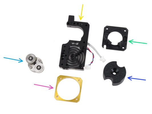
⬢For this chapter, please prepare:
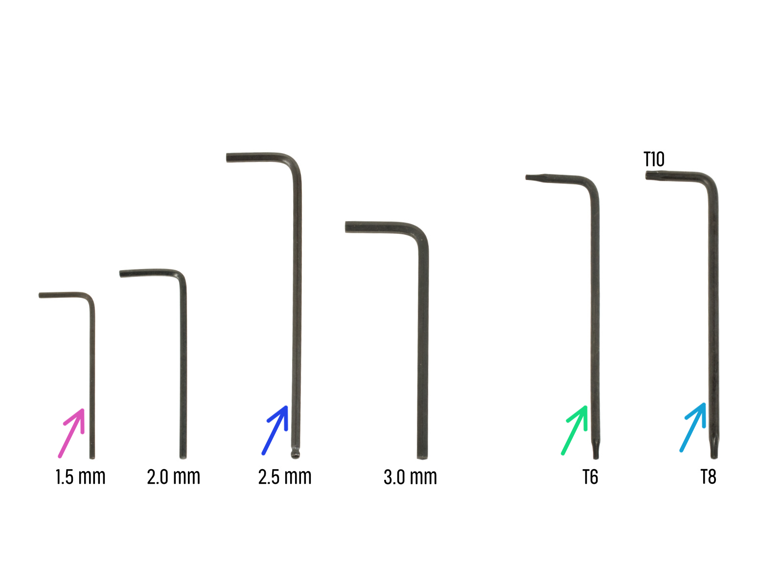
⬢1.5mm Allen key
⬢2.5mm Allen key
⬢Torx key TX6
⬢Torx key TX10/8
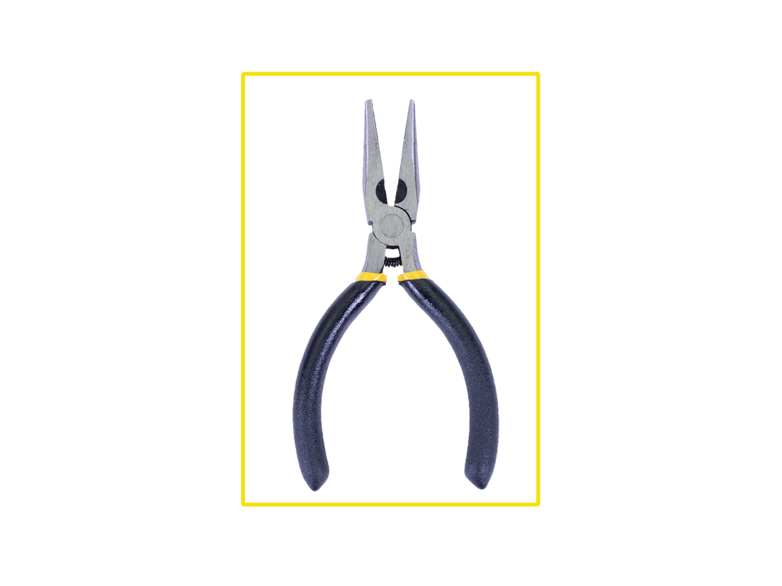
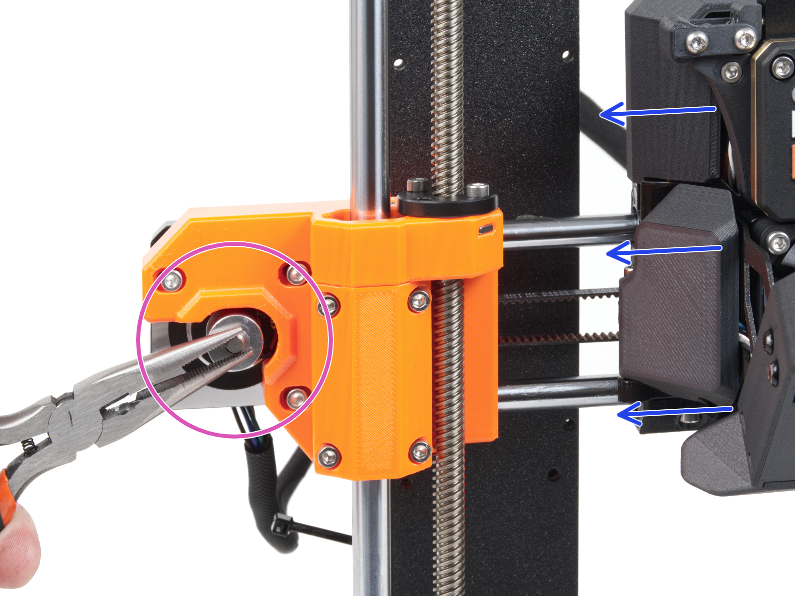
⬢Needle-nose pliers
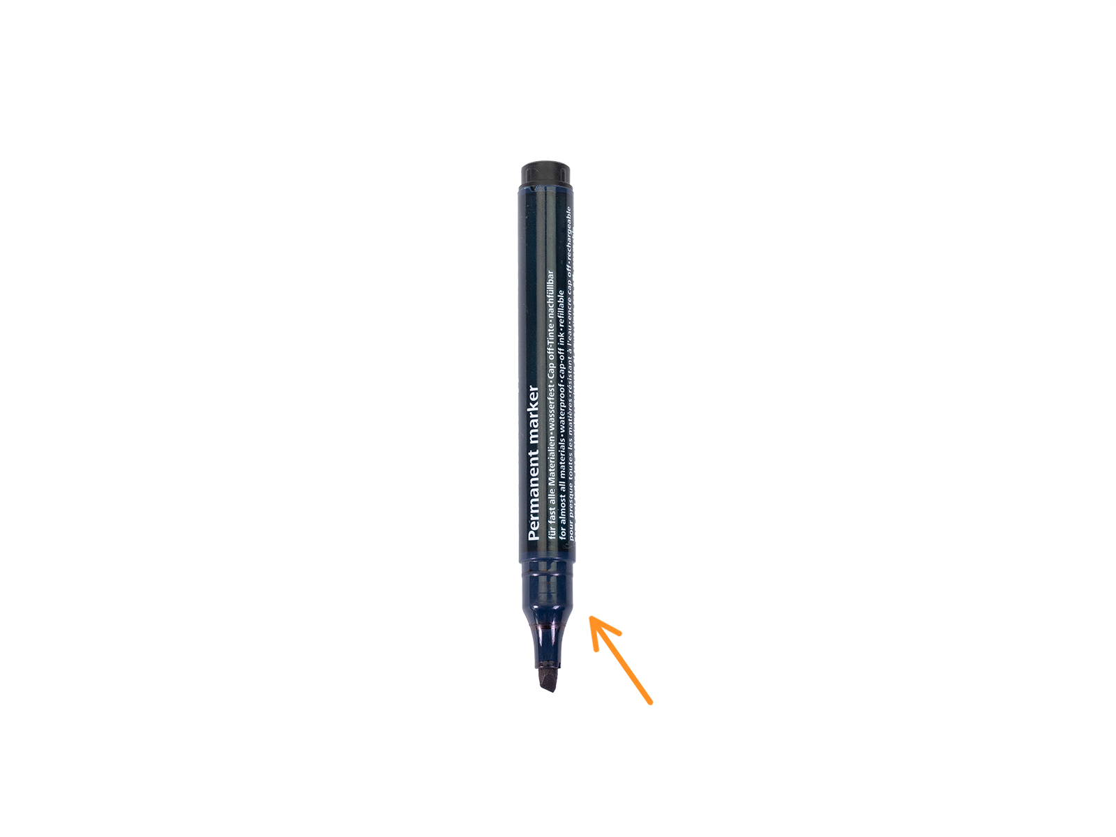
⬢Permanent marker


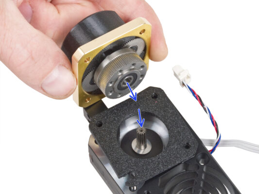

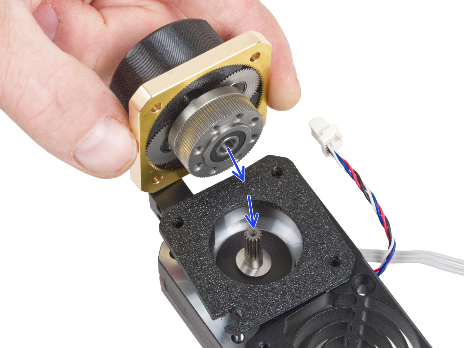


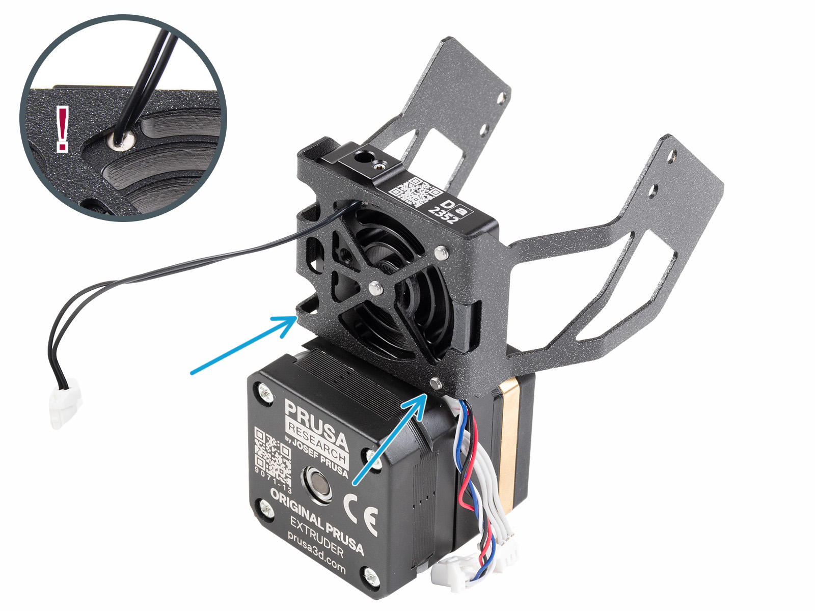

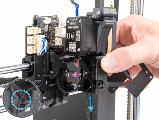
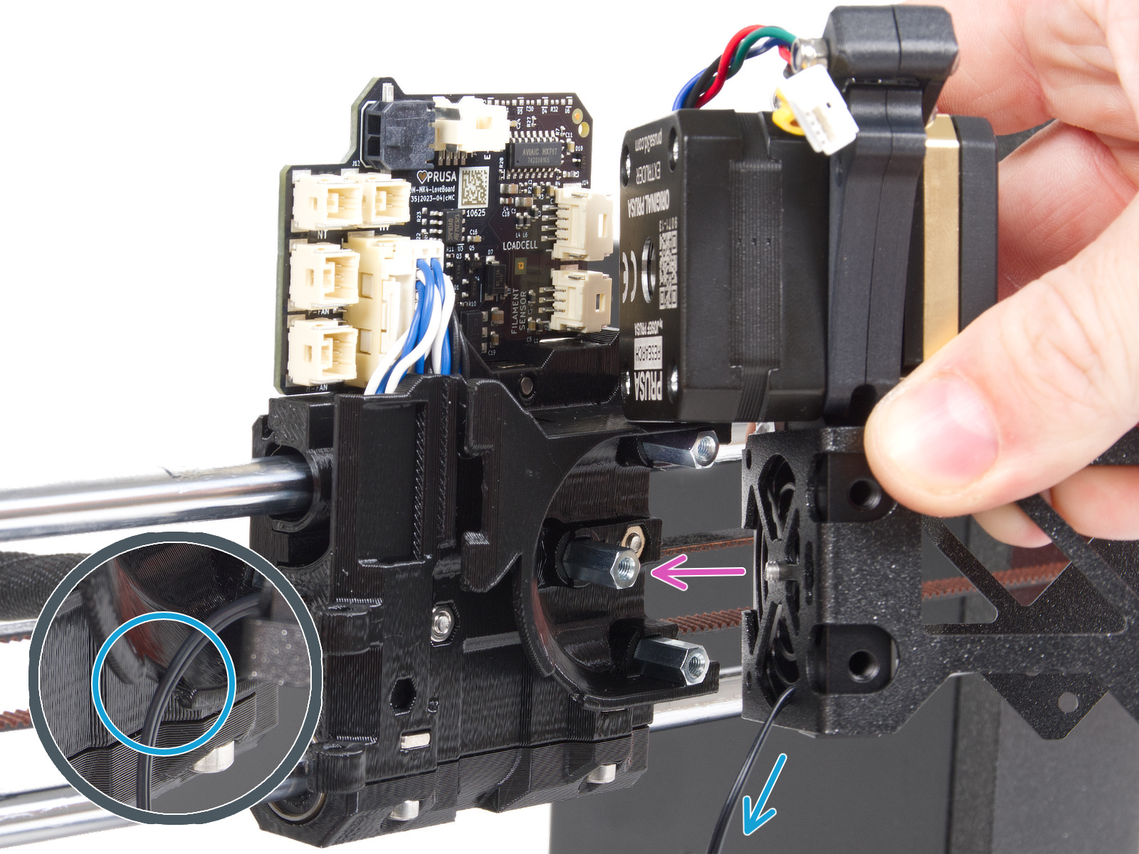

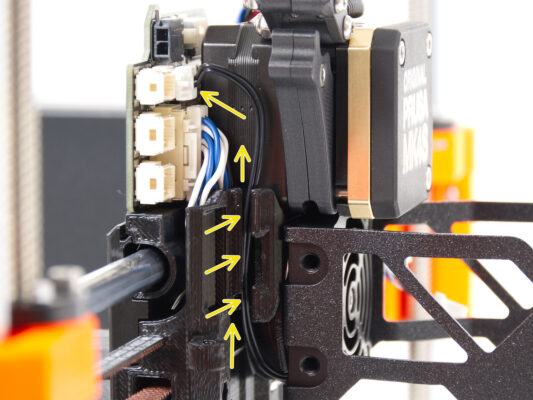
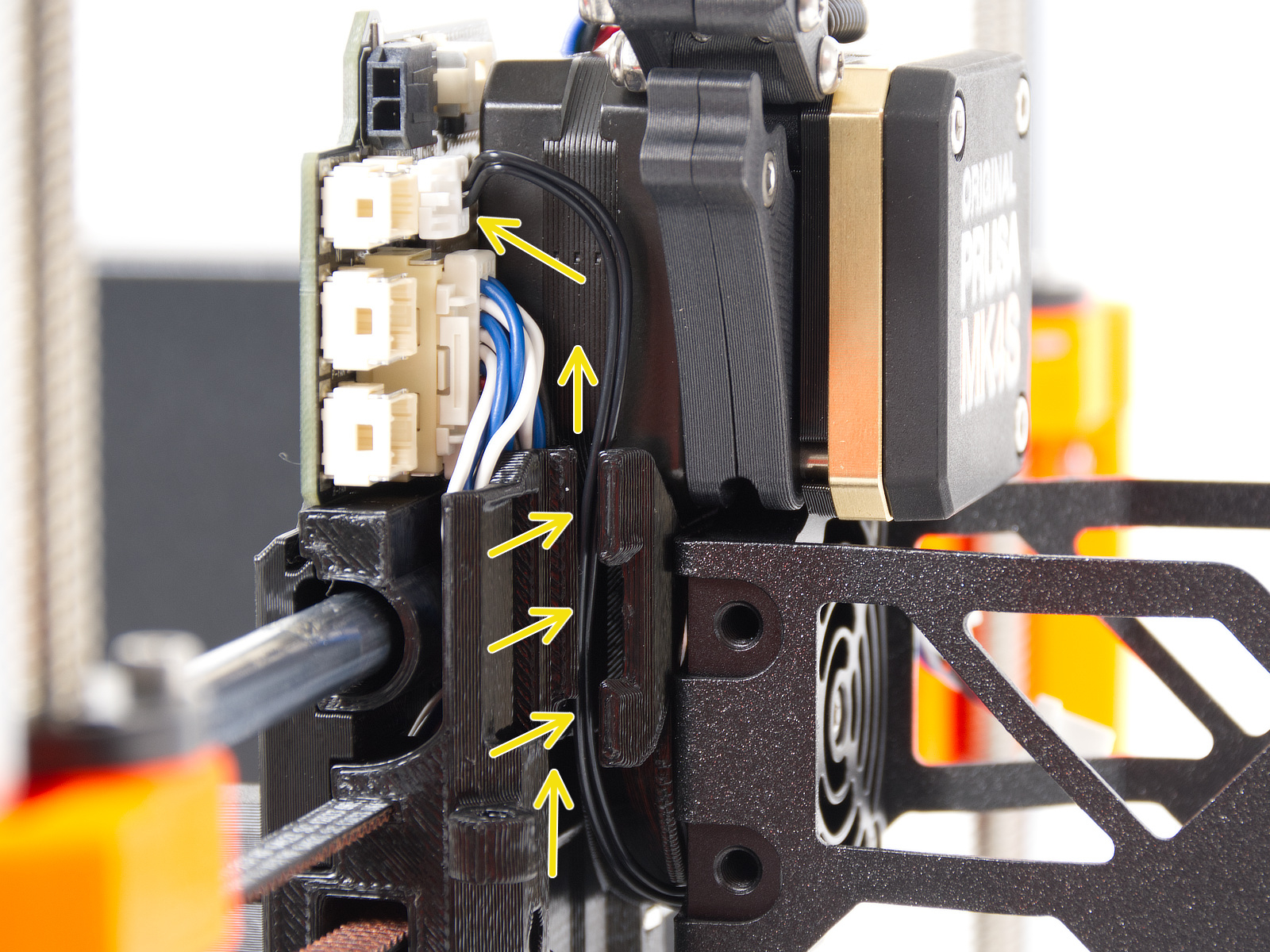
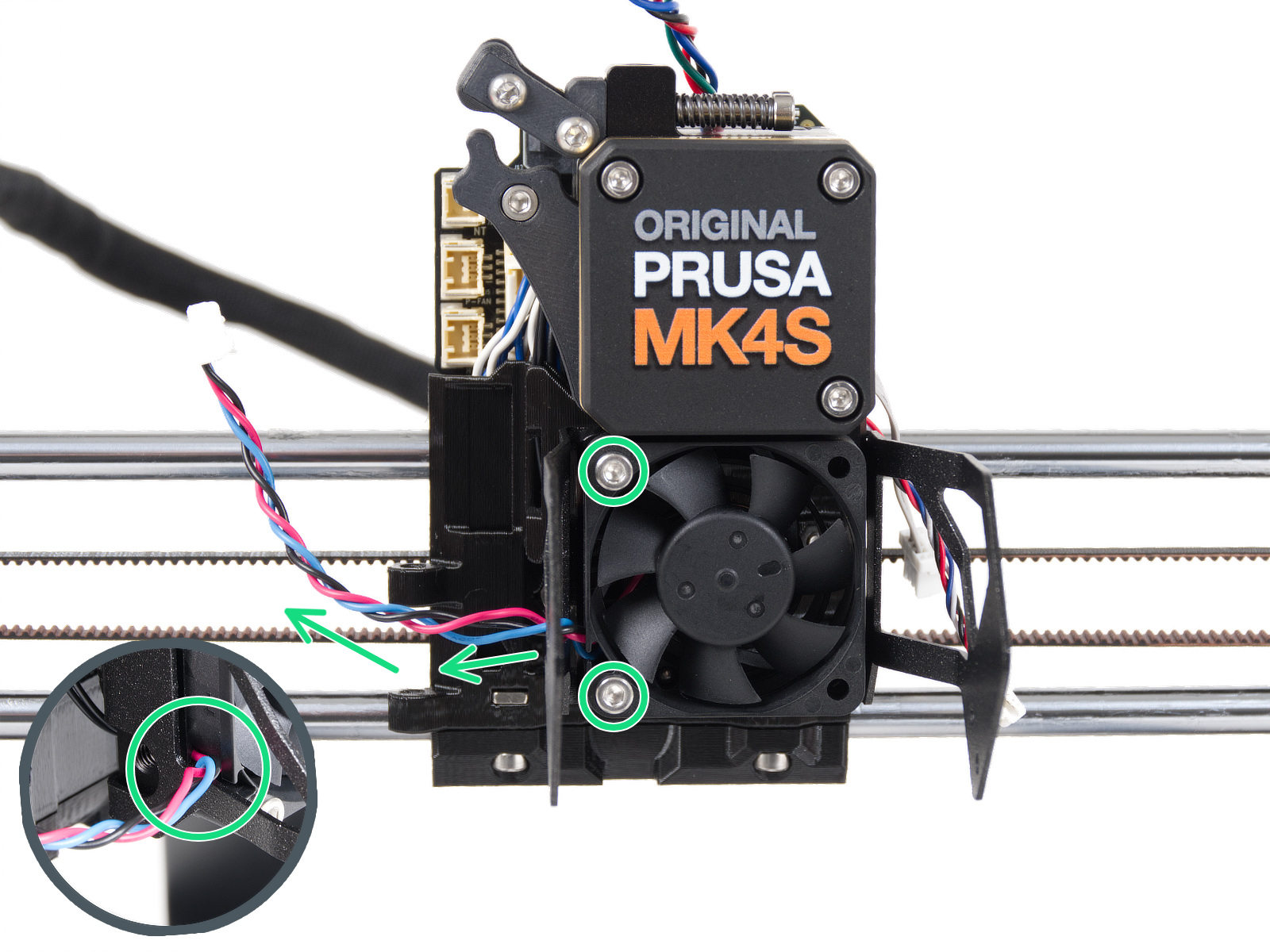
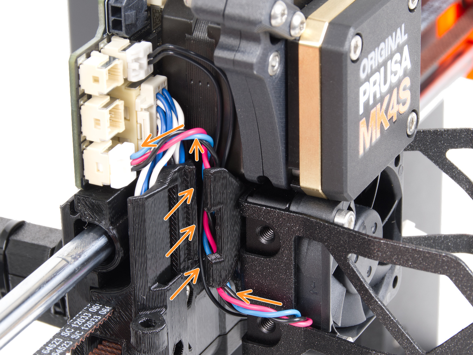
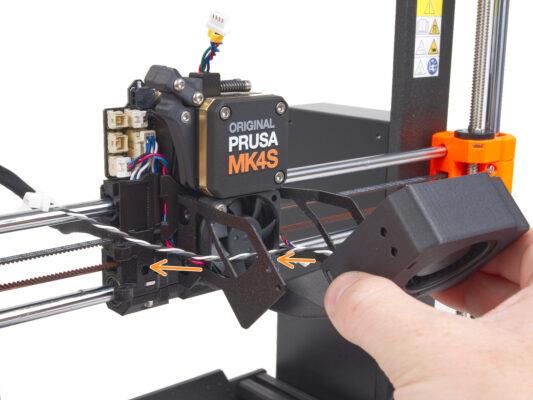
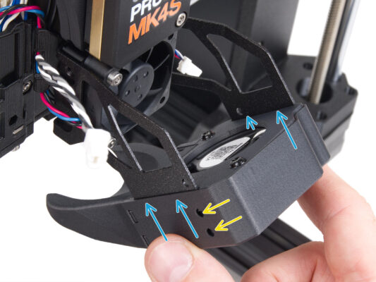
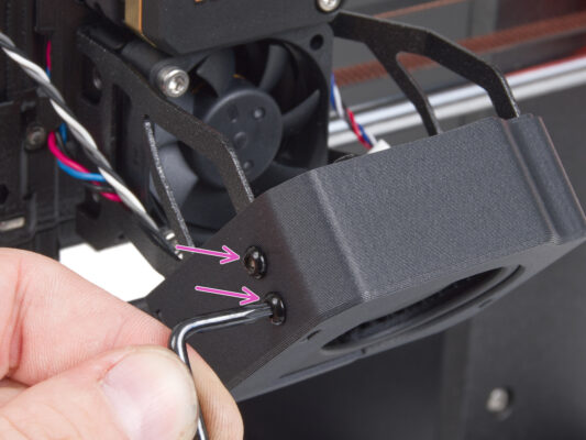
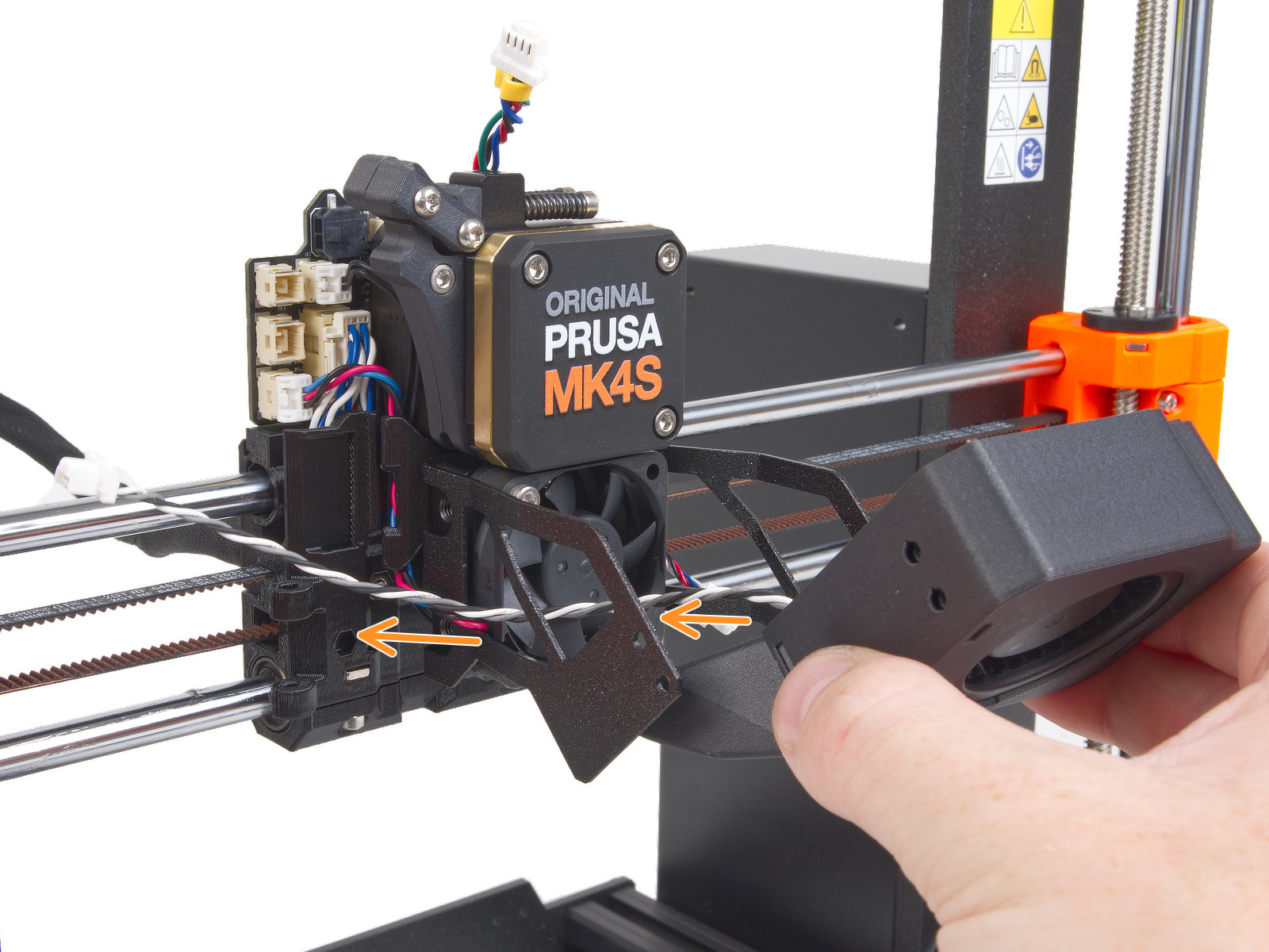
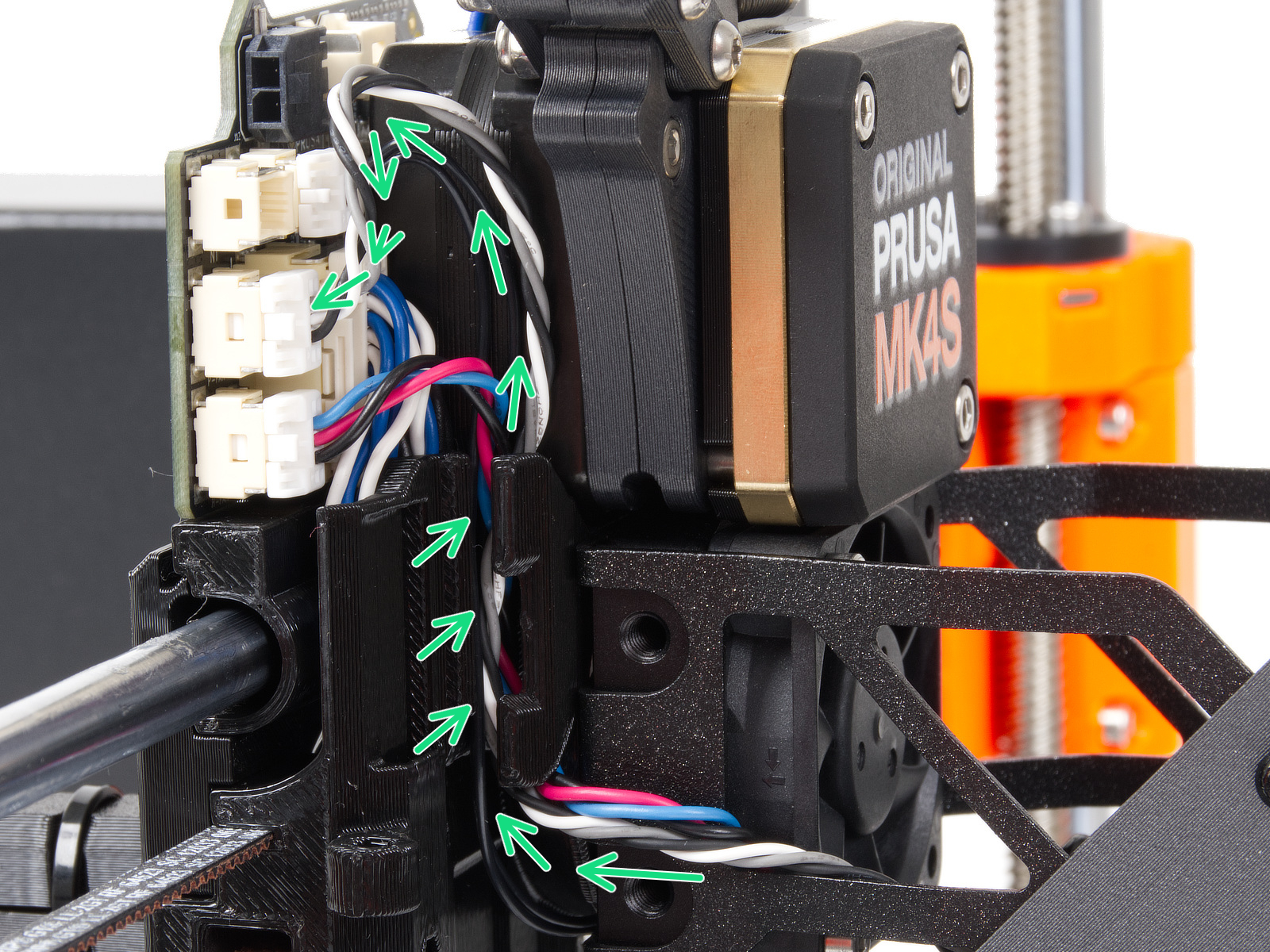
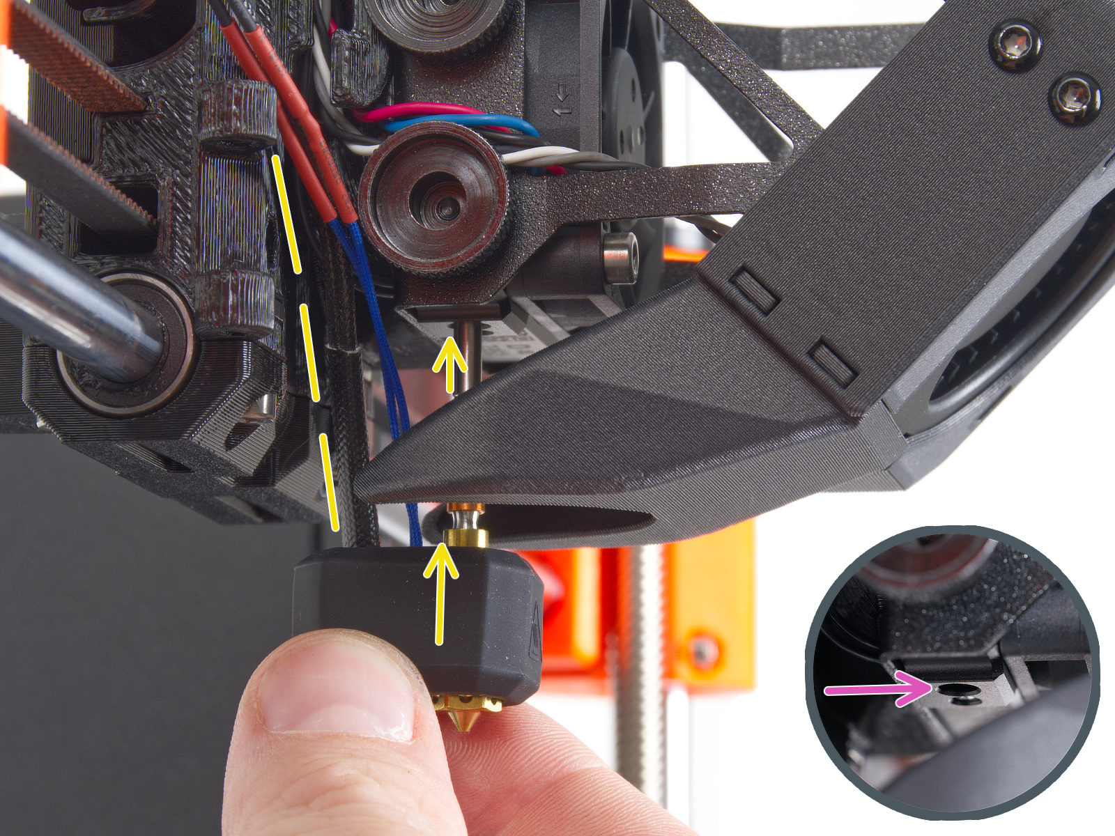
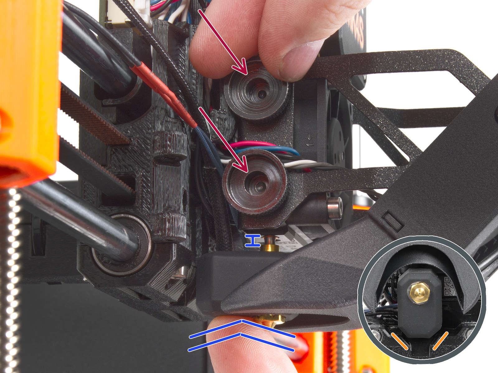
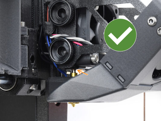
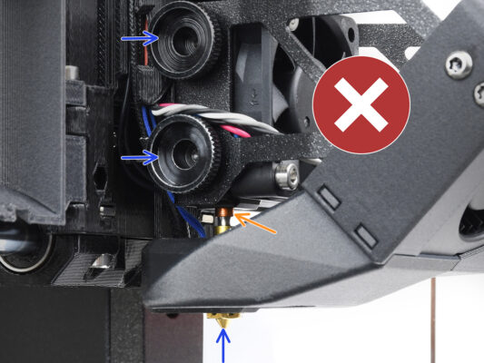
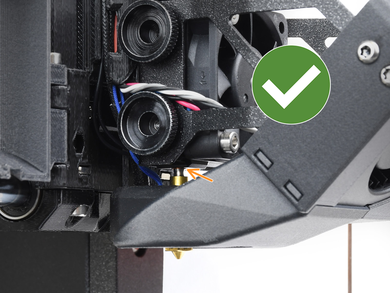
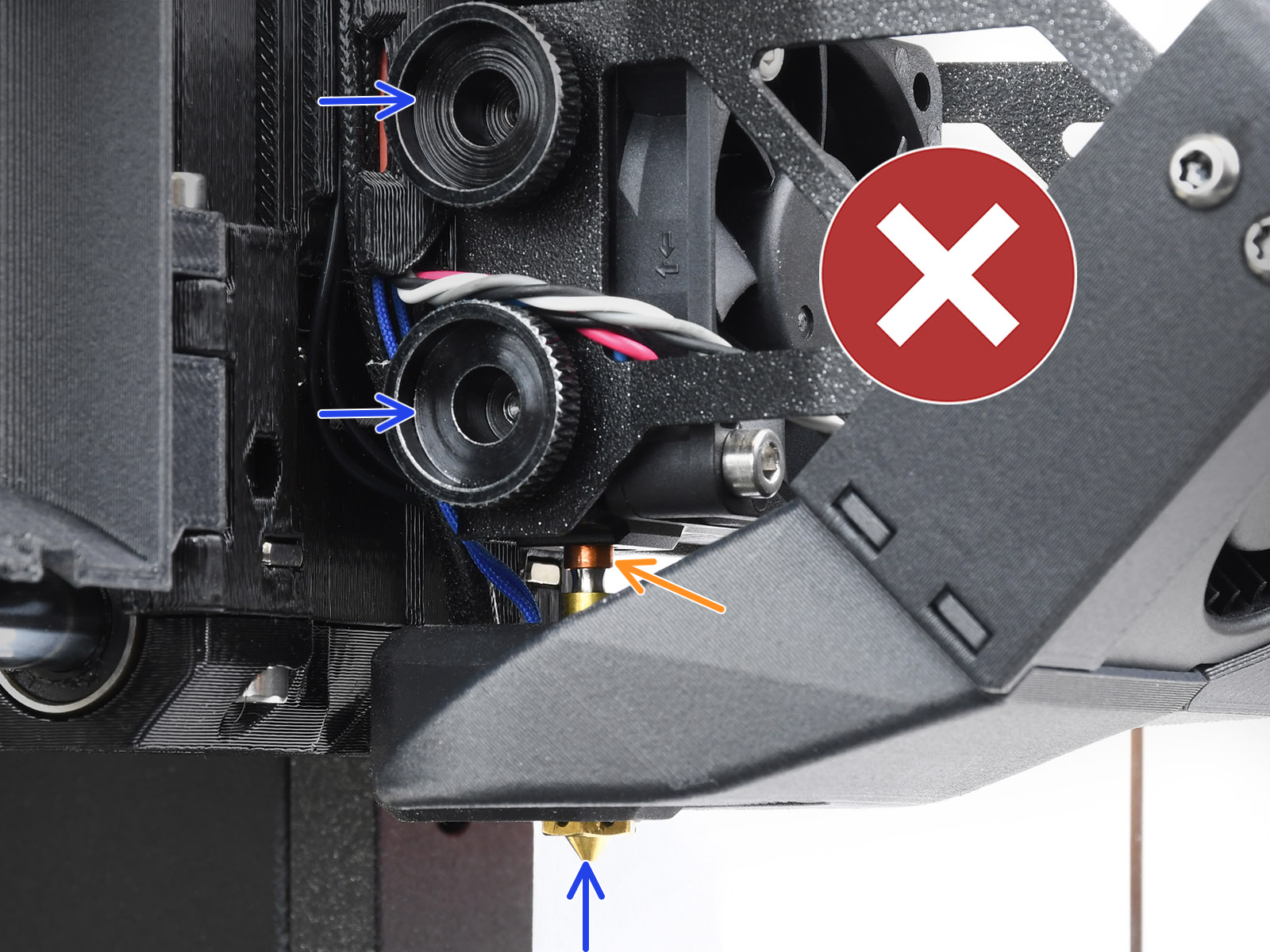
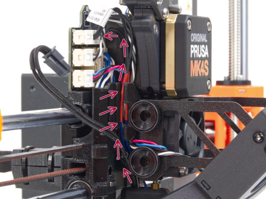
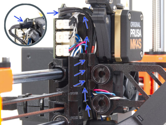
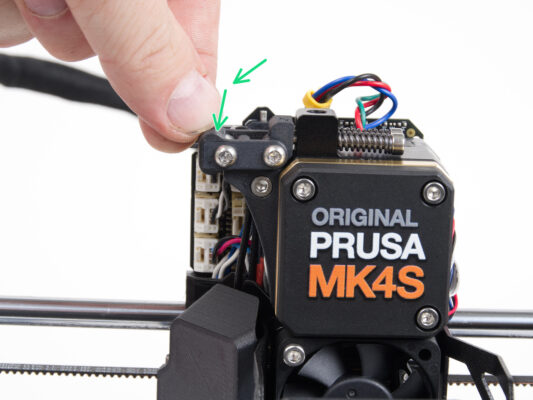
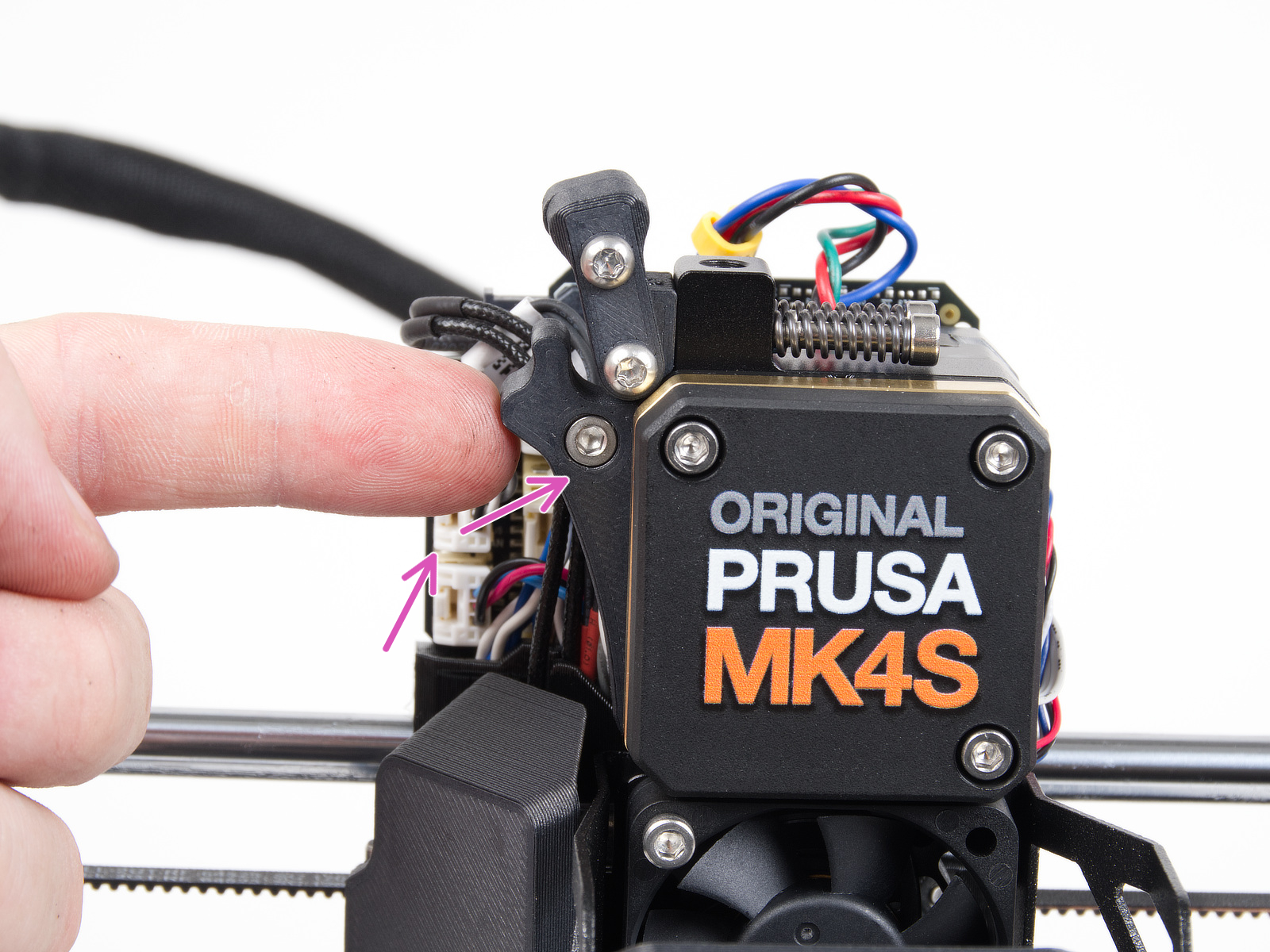
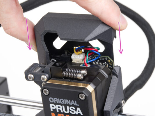
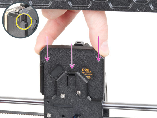
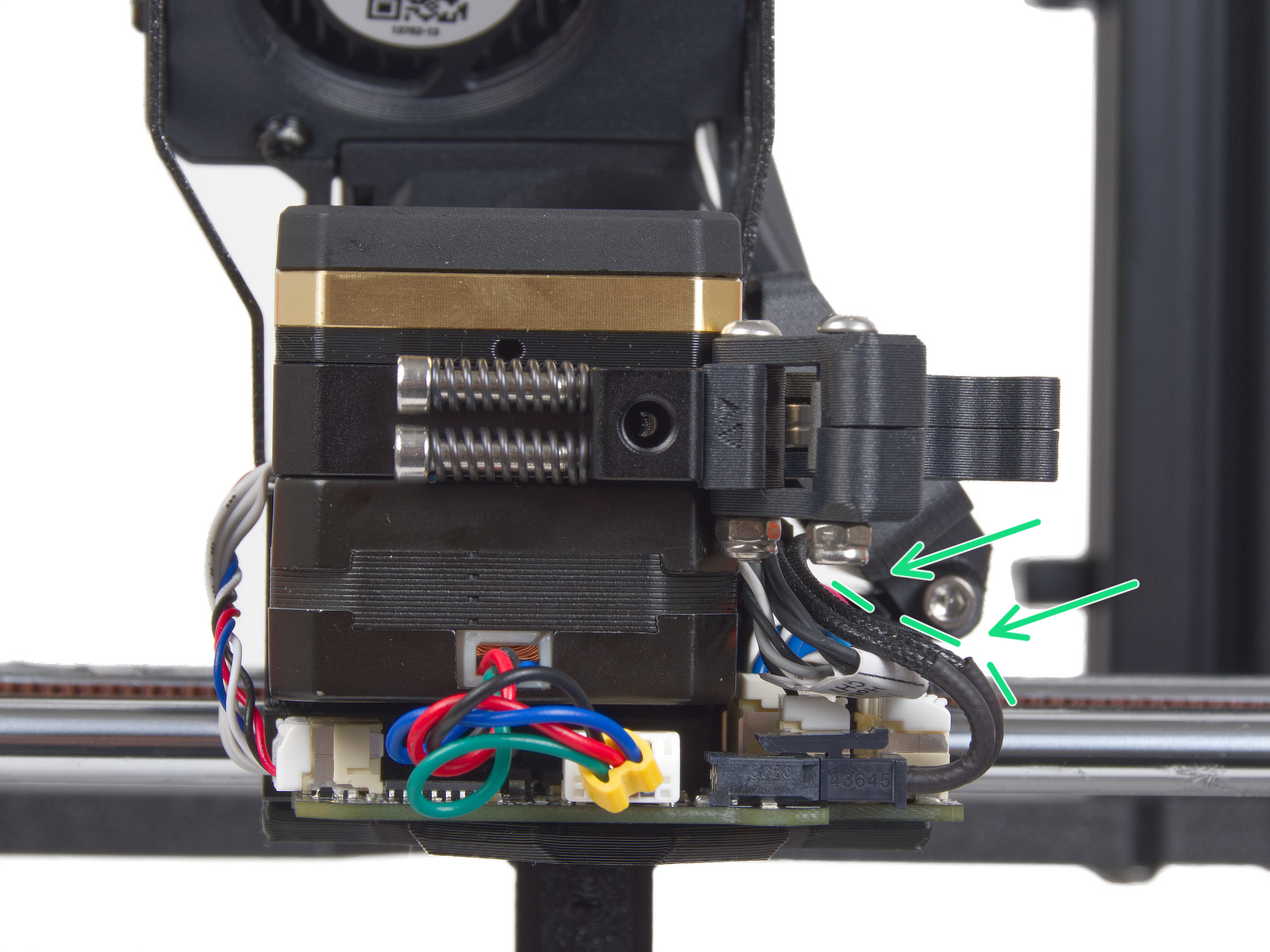
DO NOT PINCH ANY OF THE CABLES!


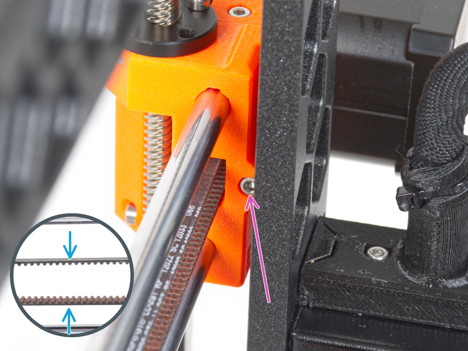
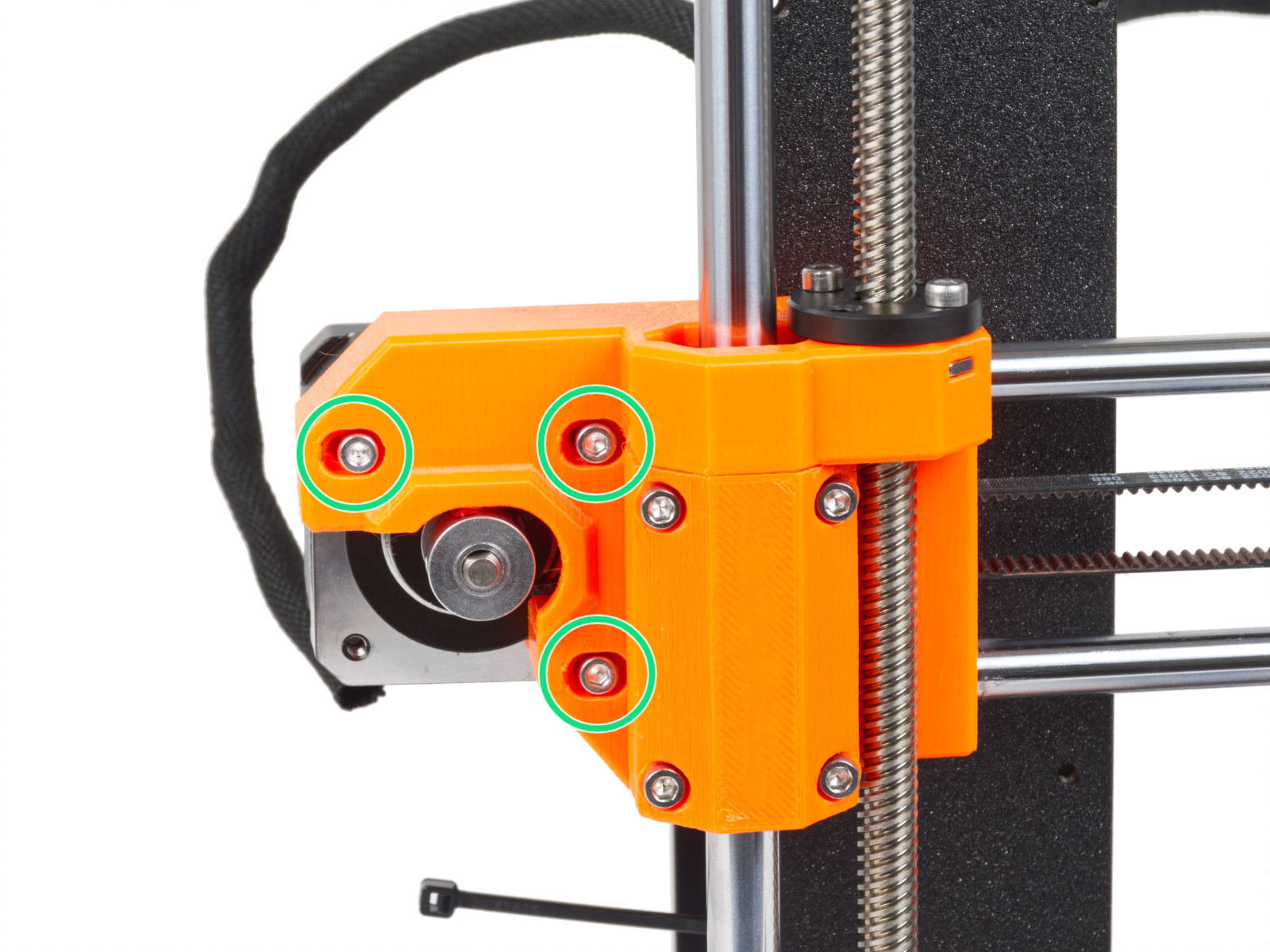
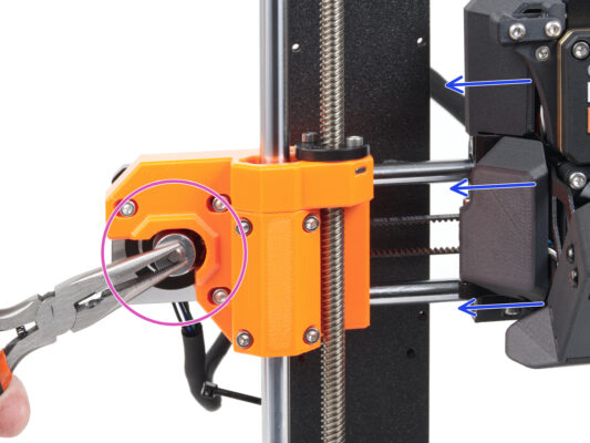
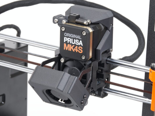
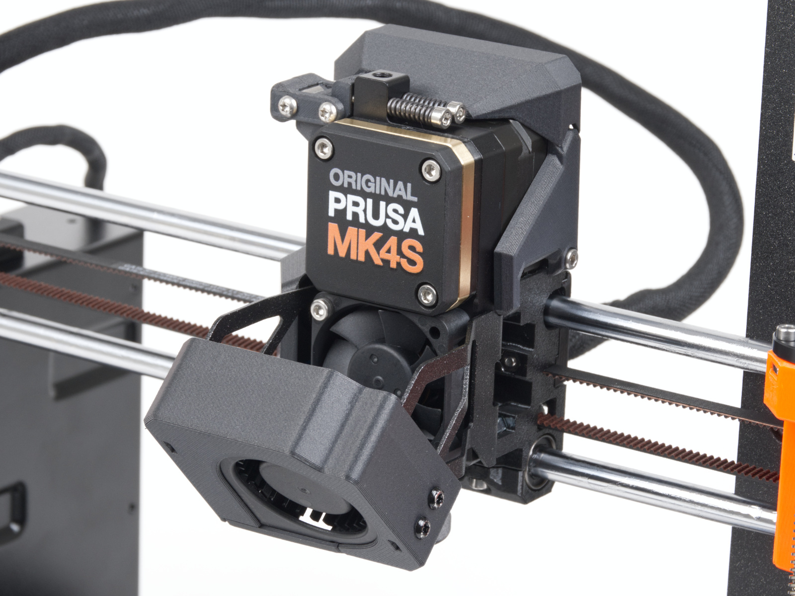
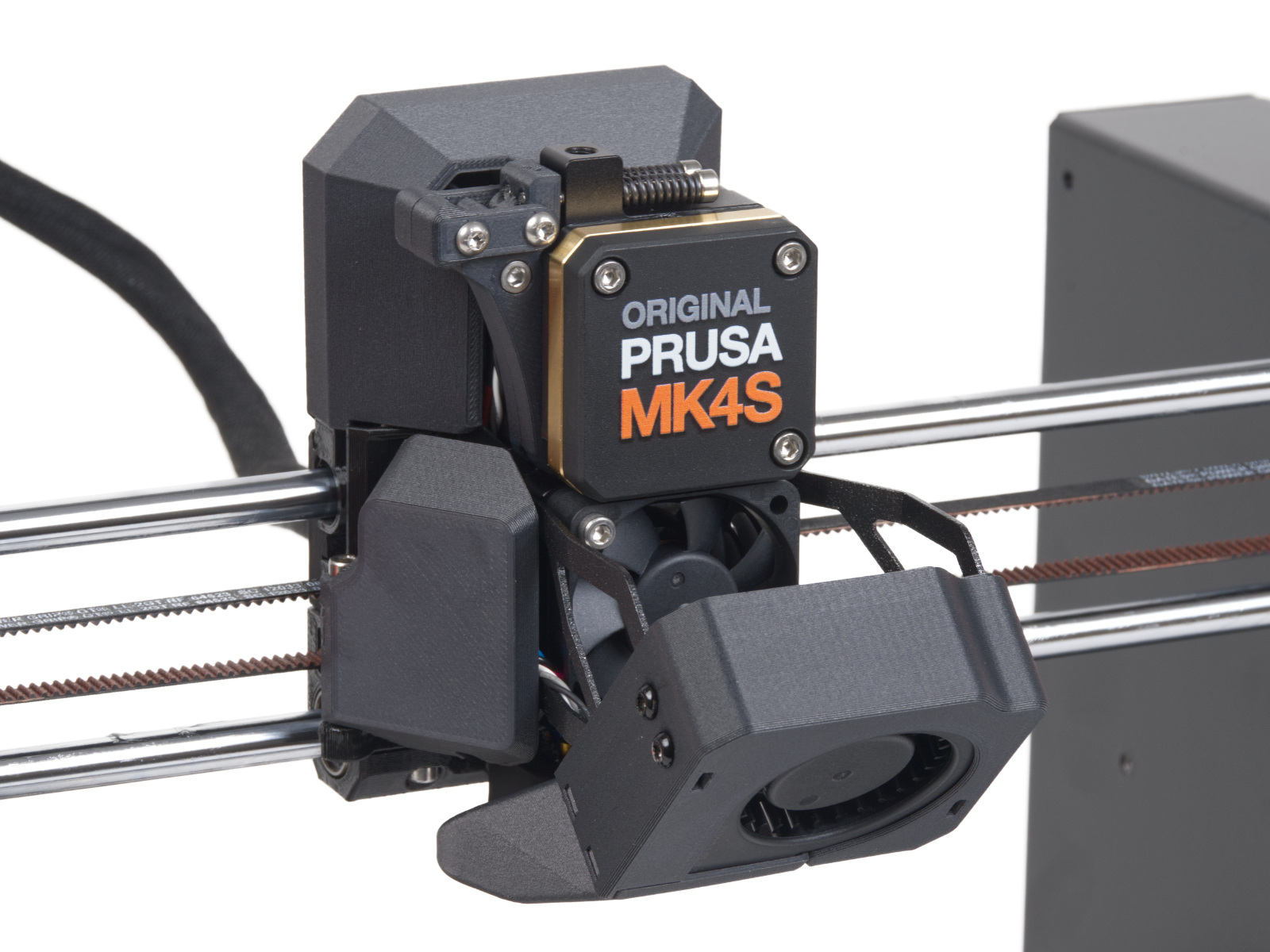
For optimal performance, the belt must have some resistance when pressed with your fingers. Move the extruder to the X-end-idler and try the belt tension in the middle of the X-axis.


If you have a question about something that isn't covered here, check out our additional resources.
And if that doesn't do the trick, you can send an inquiry to [email protected] or through the button below.

