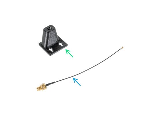
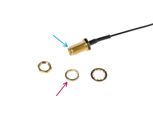
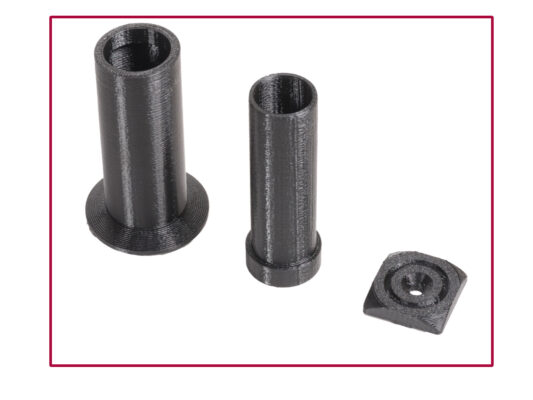
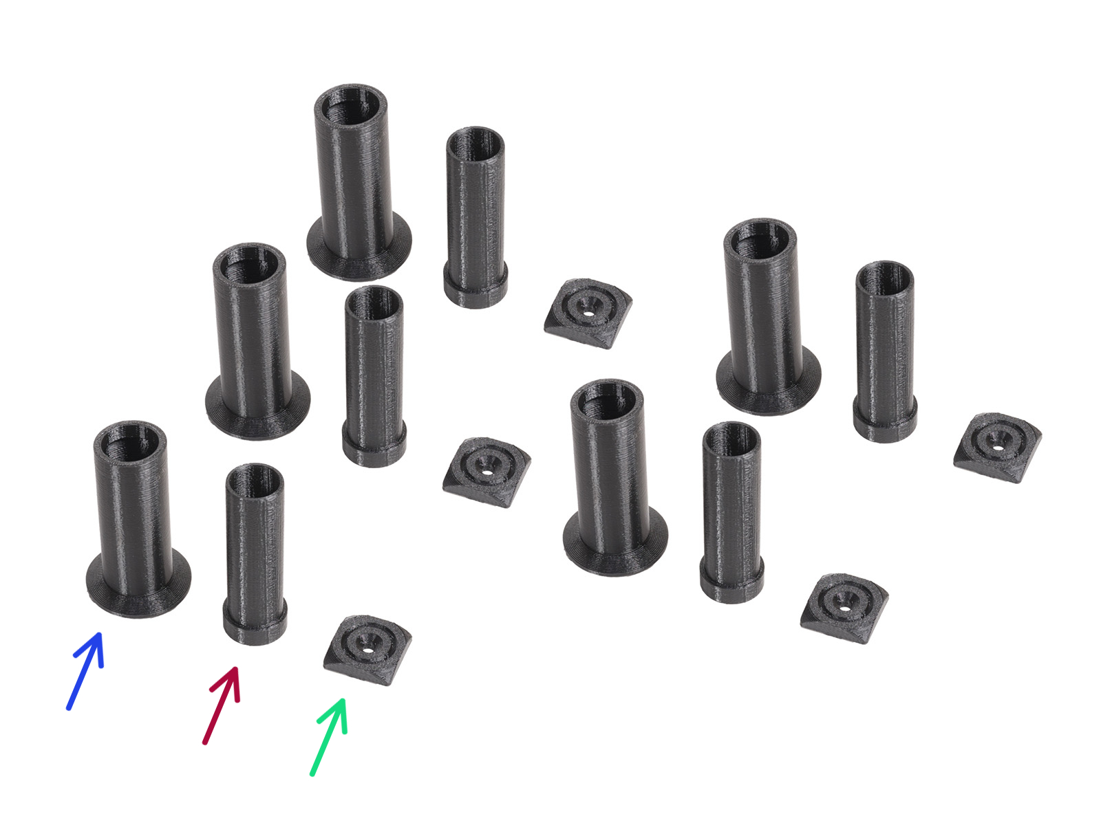
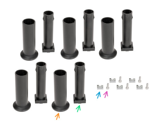
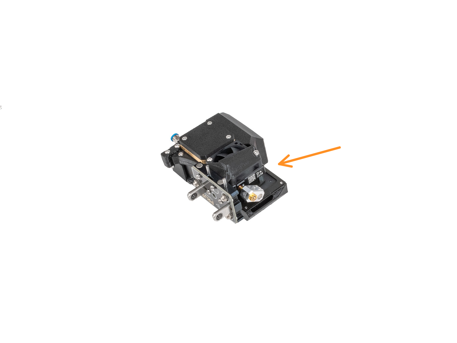
EN
  • Čeština
  • Español
  • Italiano
  • Deutsch
  • Polski
  • Français
Login

6. Extruder & accessories assembly

Menu

6. Extruder & accessories assembly

6. Extruder & accessories assembly
Relevant for:
Last updated 17 days ago
6. Extruder & accessories assembly
 Difficulty
Very easy
 Steps
43
 Available languages
CSPLDEESITFR
Filament sensor: parts preparation
For the following steps, please prepare:
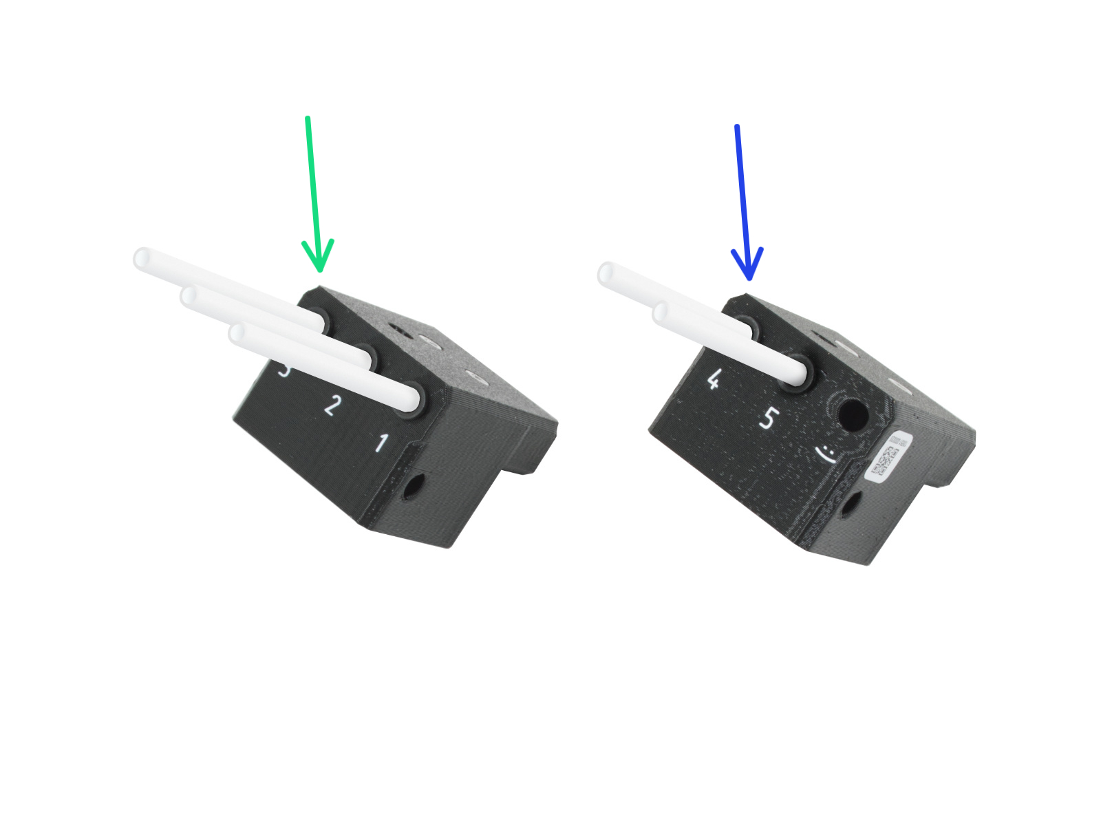
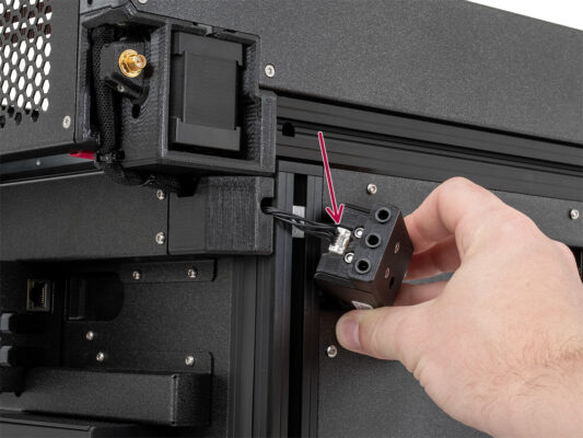
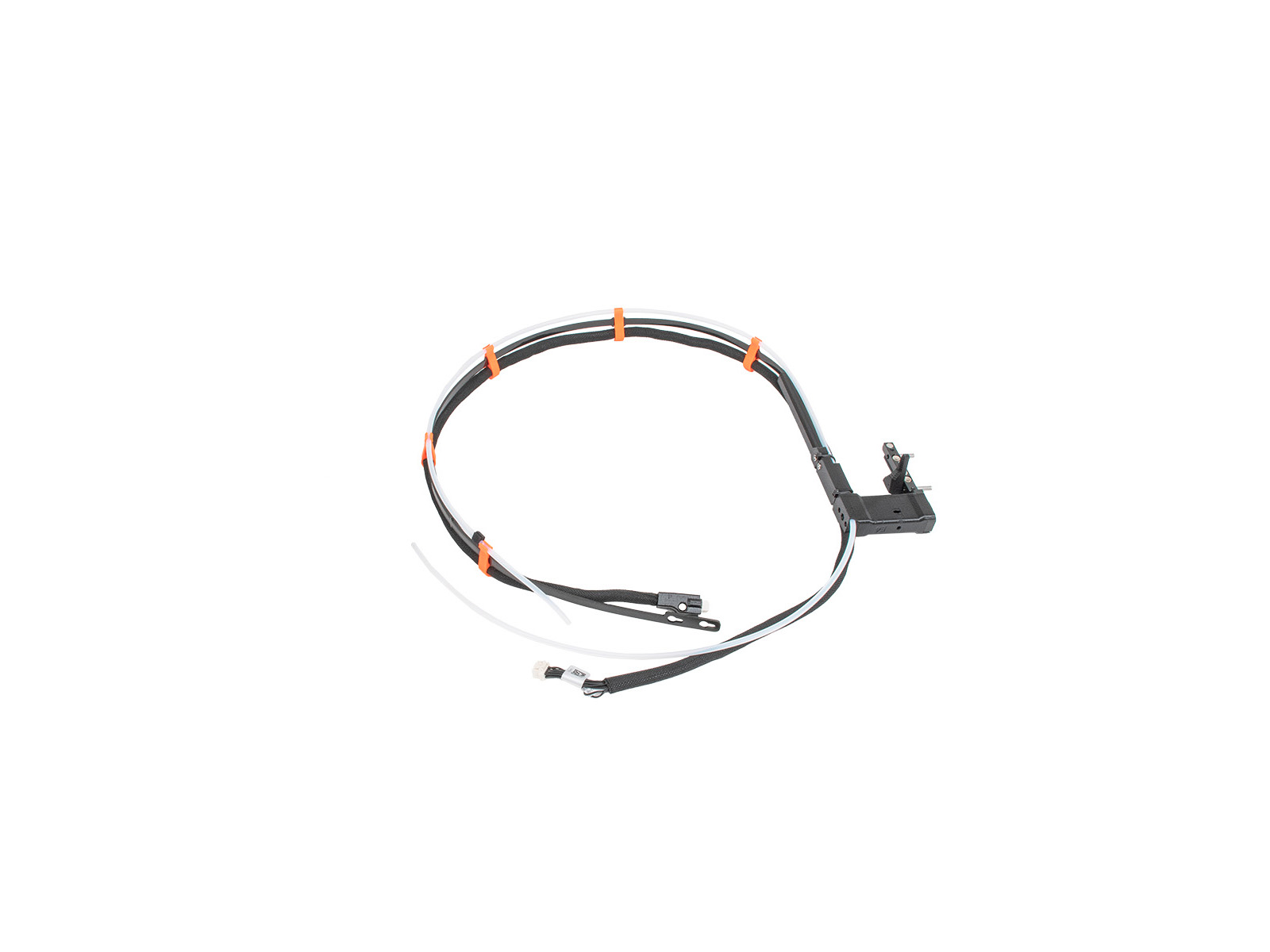
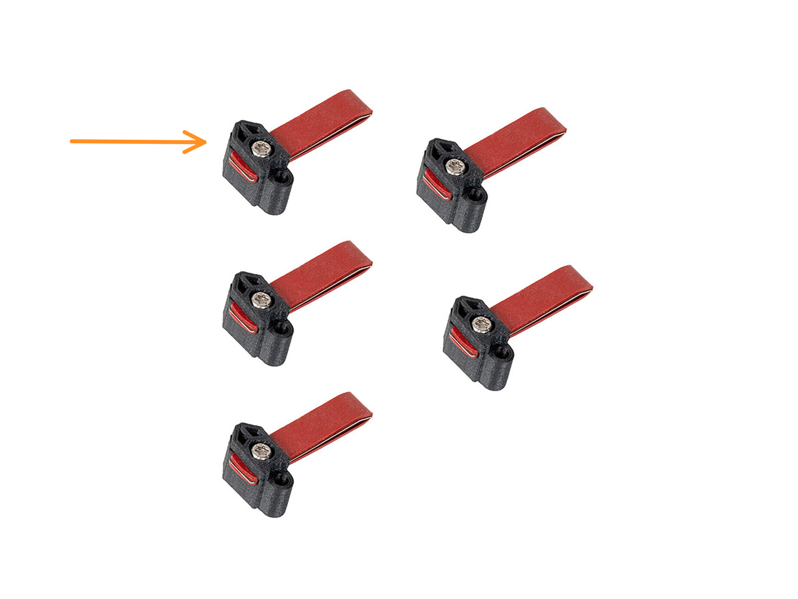
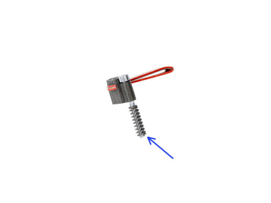
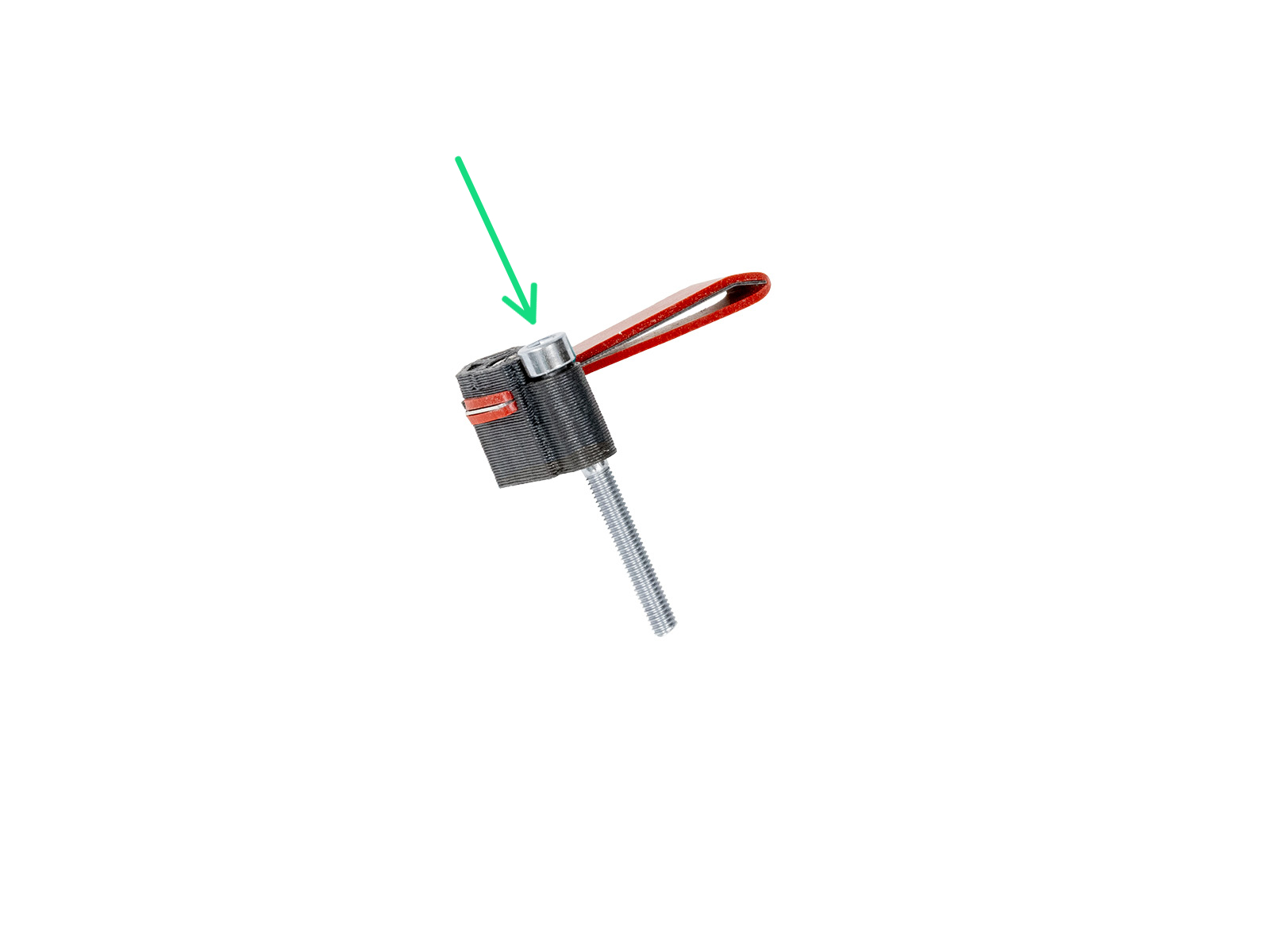
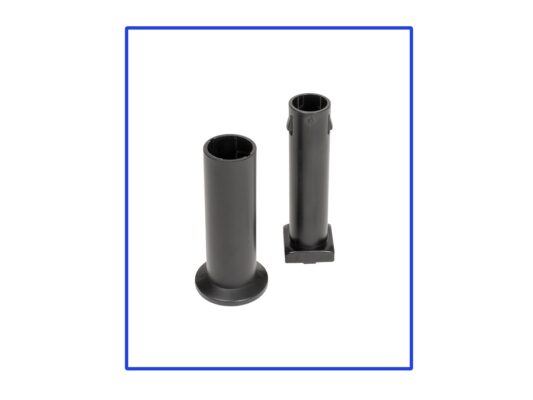
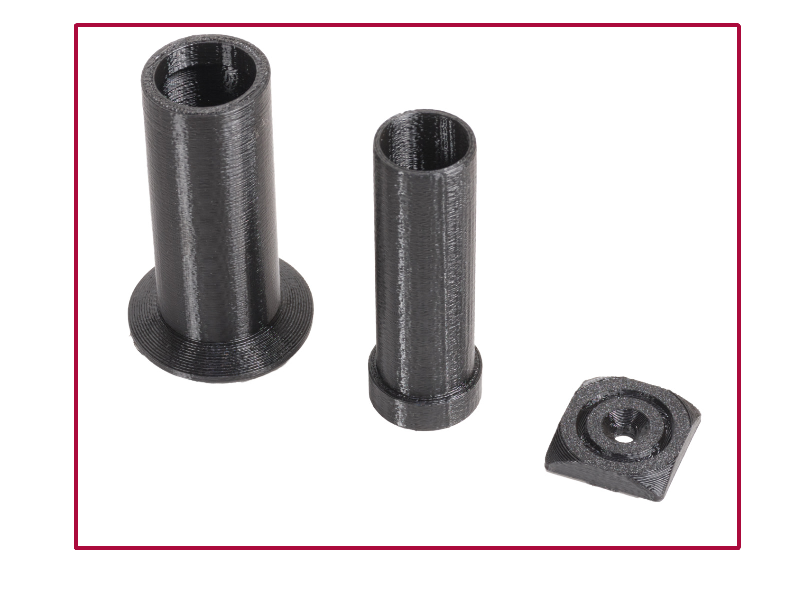
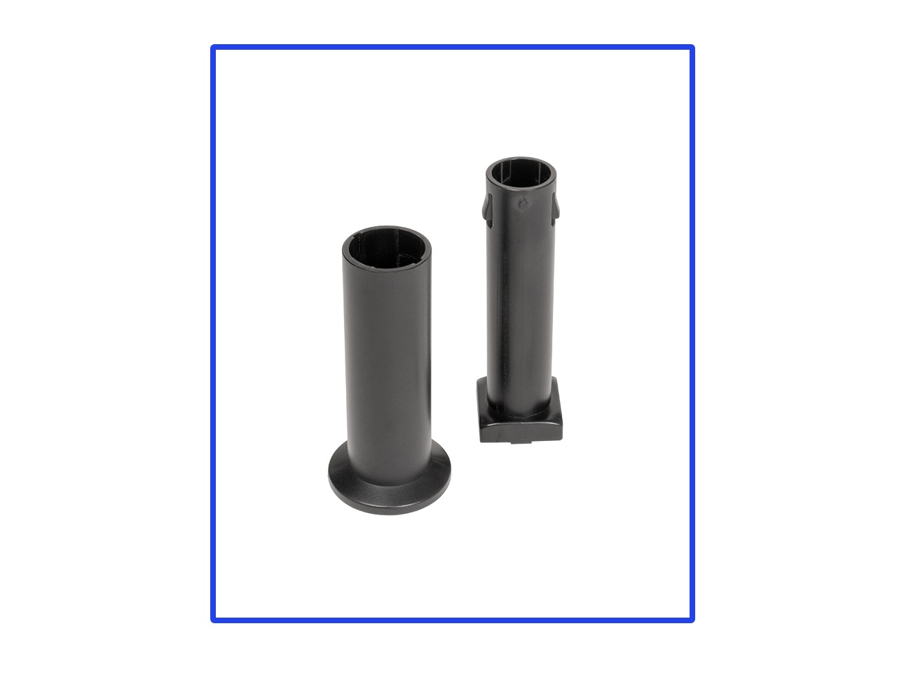
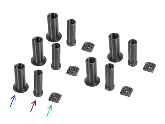
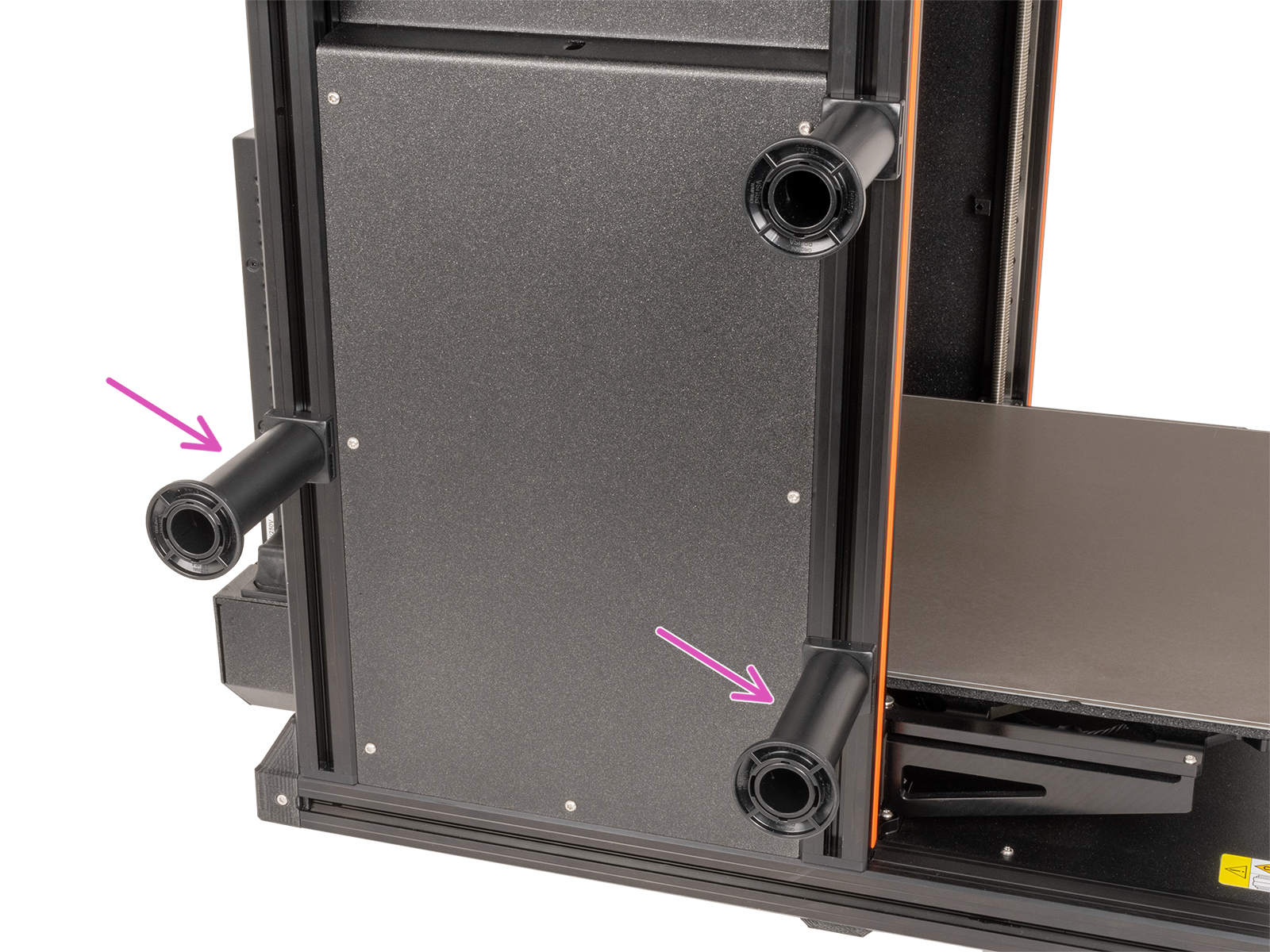
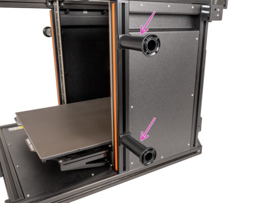
Filament sensor assembly - left (1x)
Side filament sensor assembly - right (1x)
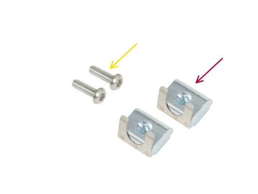
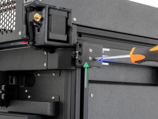
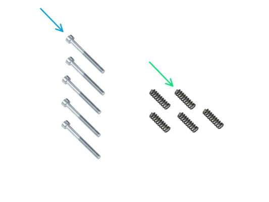
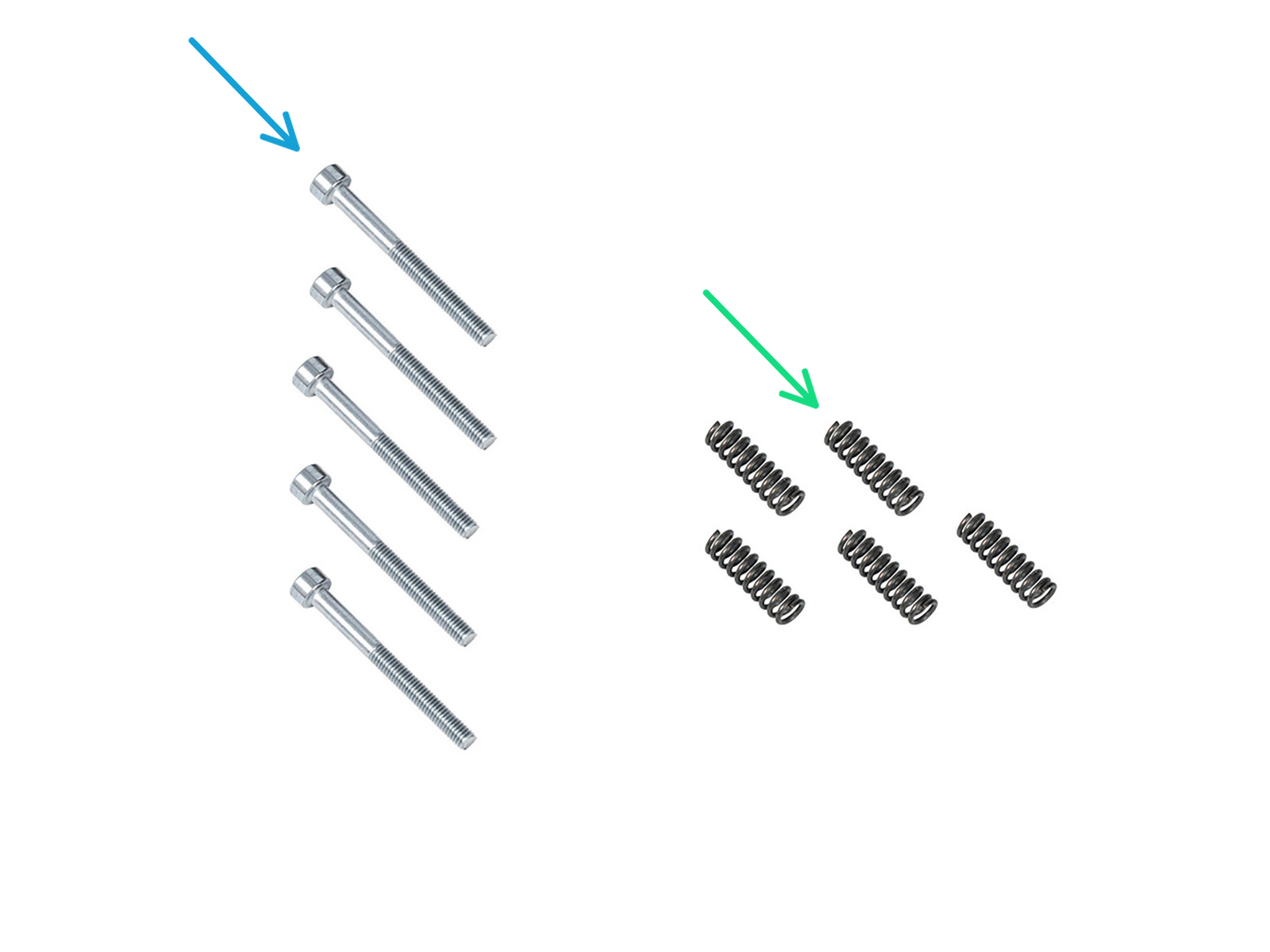
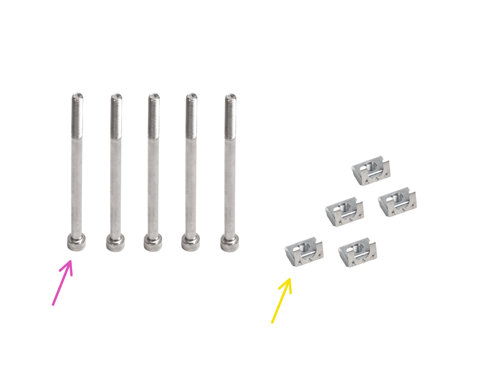
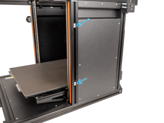
M3x12rT screw (2x)
M3nEs nut (2x)
Inserting the M3nEs nut
Turn the printer around so that its left side is facing you.
Insert the M3nEs nut into the vertical extrusion on the rear of the left side.
Attaching the filament sensors
Connect the filament sensor cable into the filament sensor assembly.
Move the filament sensor assembly to the top of the extrusion and align the M3nEs nut so that it aligns with the opening on the filament sensor assembly.
Attach the filament sensor to the M3nEs nut using the M3x12rT screw and T10 screwdriver.
Repeat the same procedure for the filament sensor on the other side
You should now have both Side Filament sensors attached.
Haribo time!
Haribo time!
It's time for another gummy bear. Take it!
Did you know that gummy bears have inspired a variety of novelty products, including gummy bear-shaped lamps, phone cases, and even shower curtains.
Nextruder dock preparing
The latest assemblies come with the nozzle seal pre-installed on the extruder dock. To confirm this, examine one of the extruder docks closely and compare it to the picture to see if the nozzle seal is already in place with the square nut. If not, continue with the text below.
Repeat this step for all tool heads:
Check that the nut is inserted in the Nextruder dock.

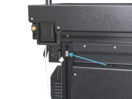
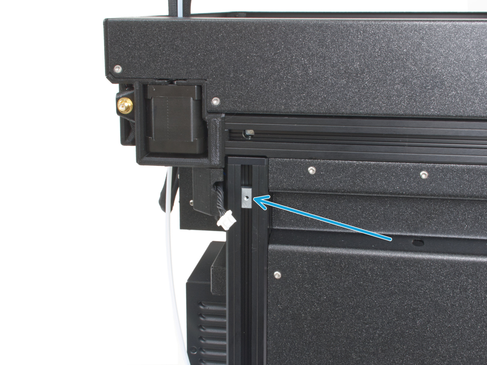
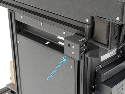
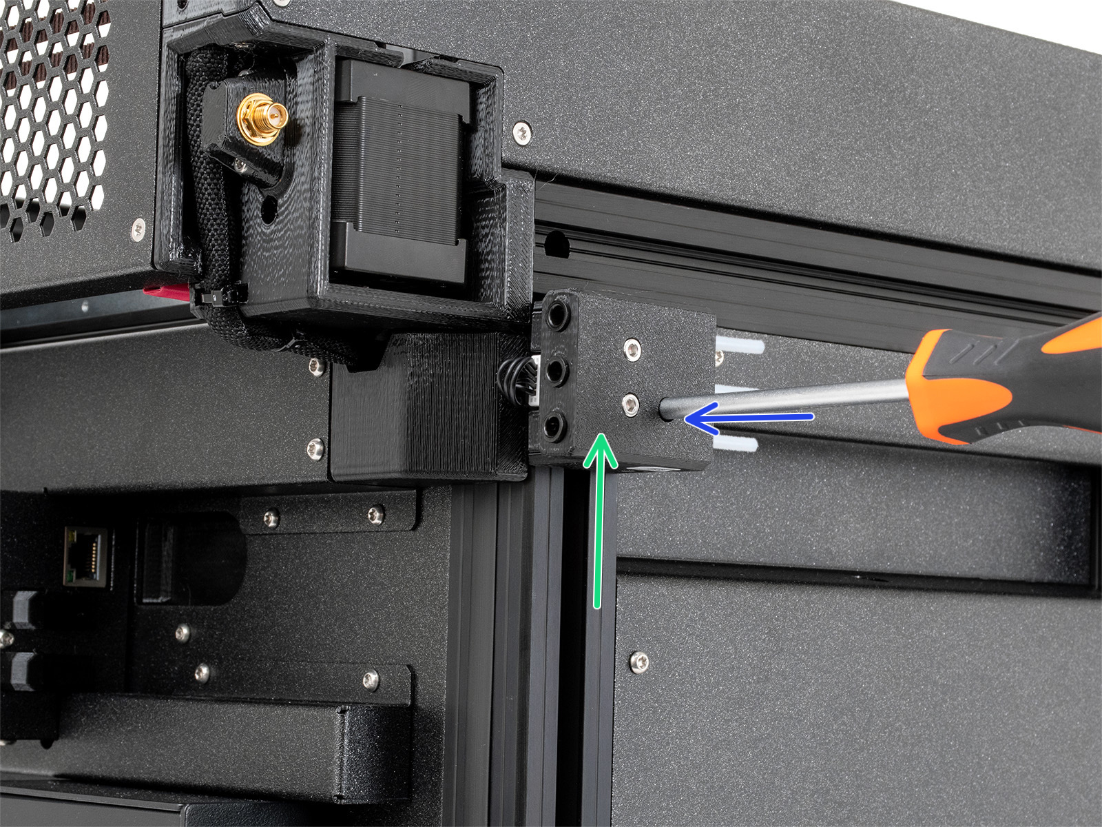
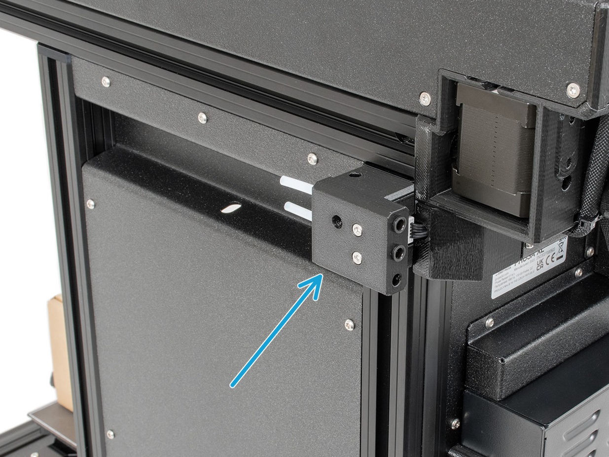
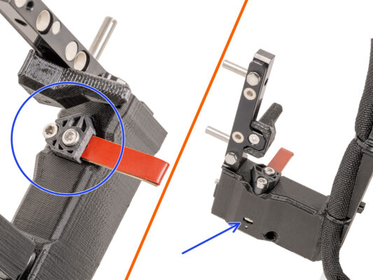
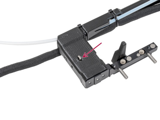
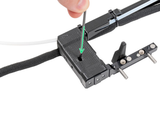
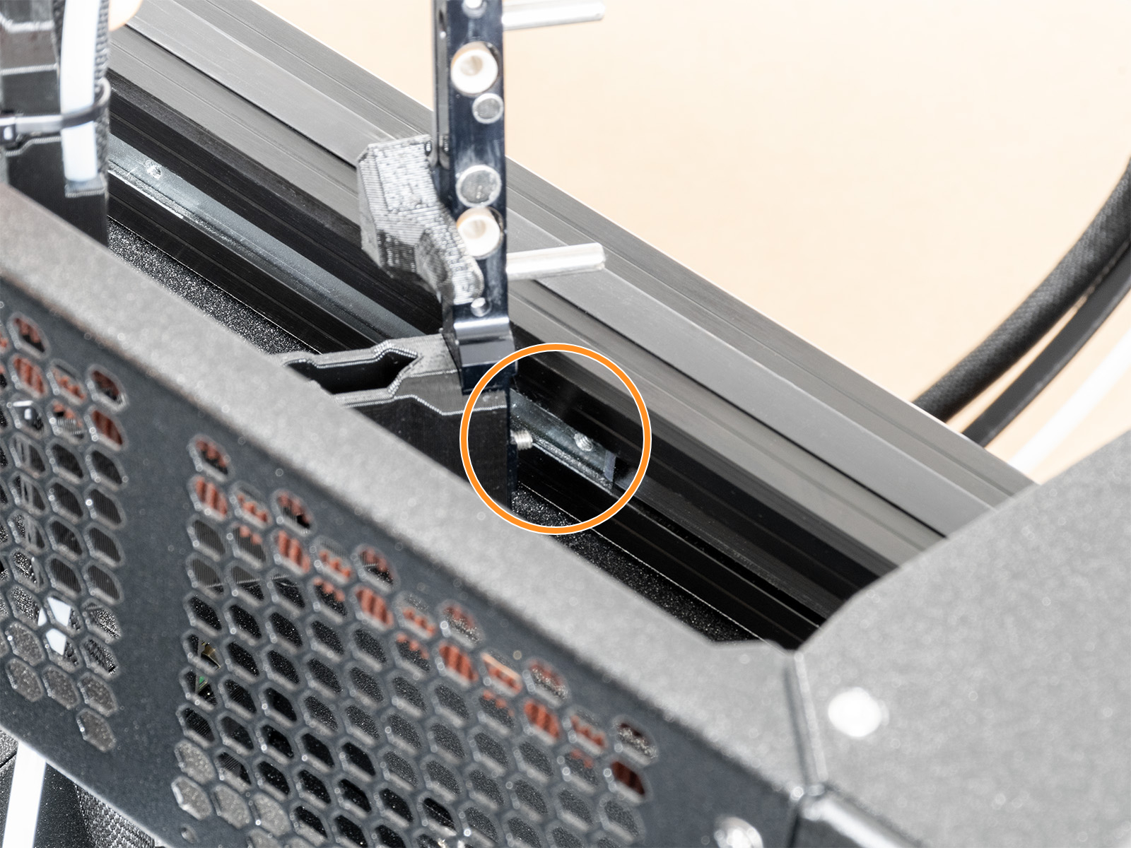
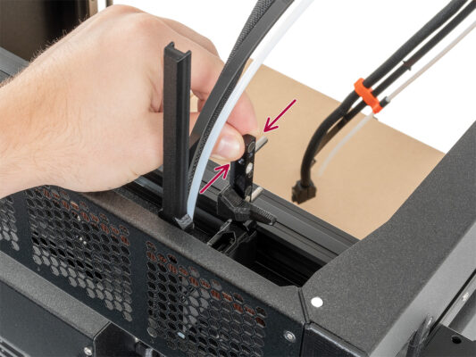
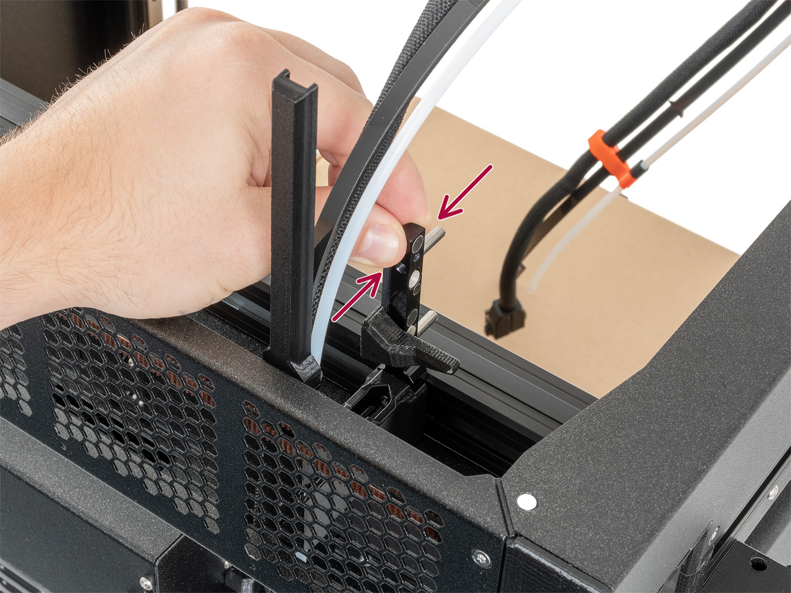
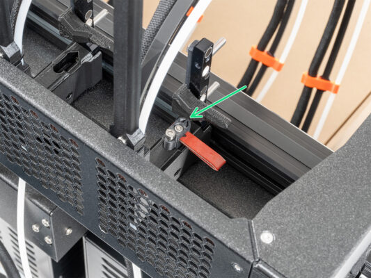
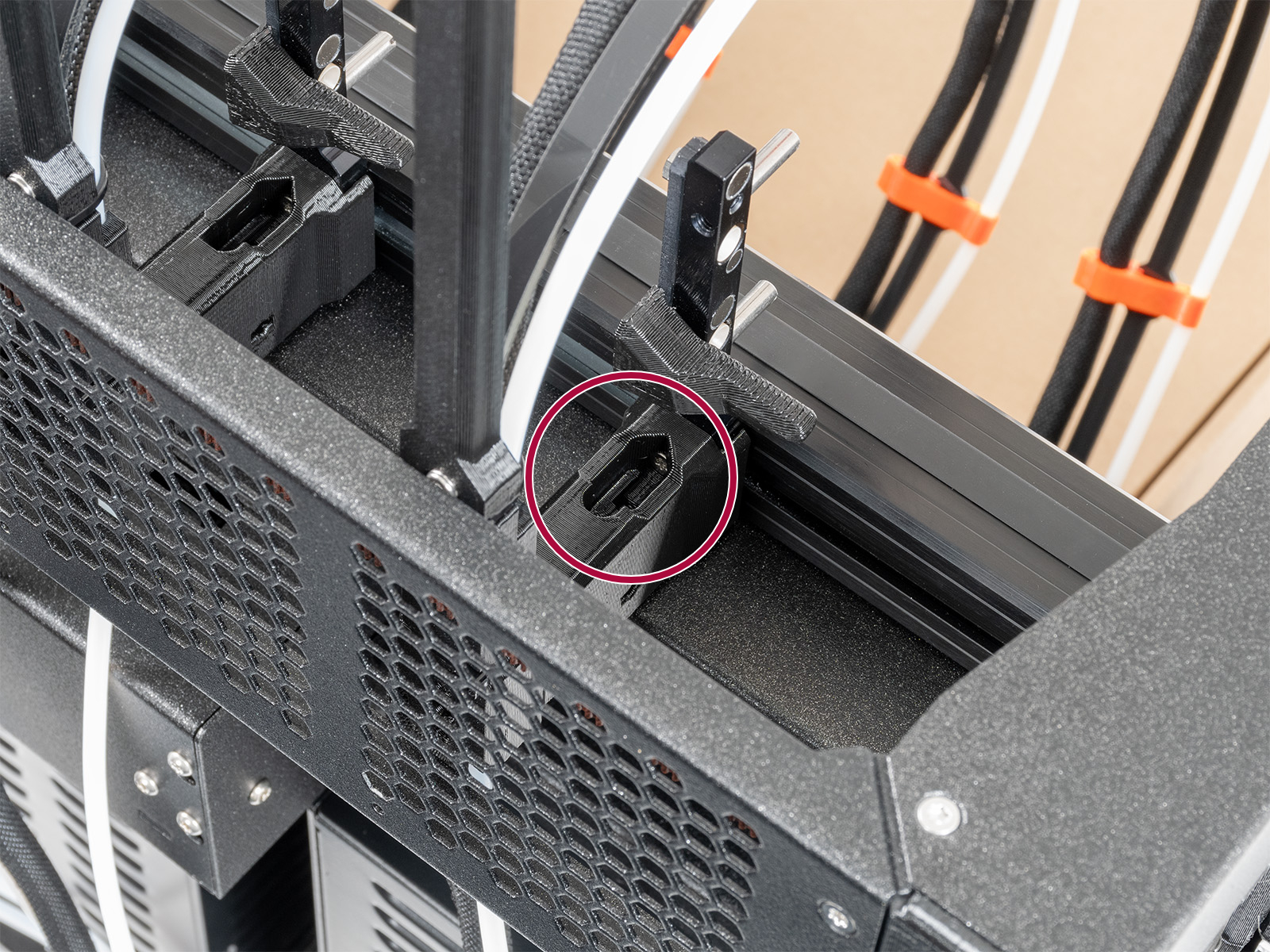
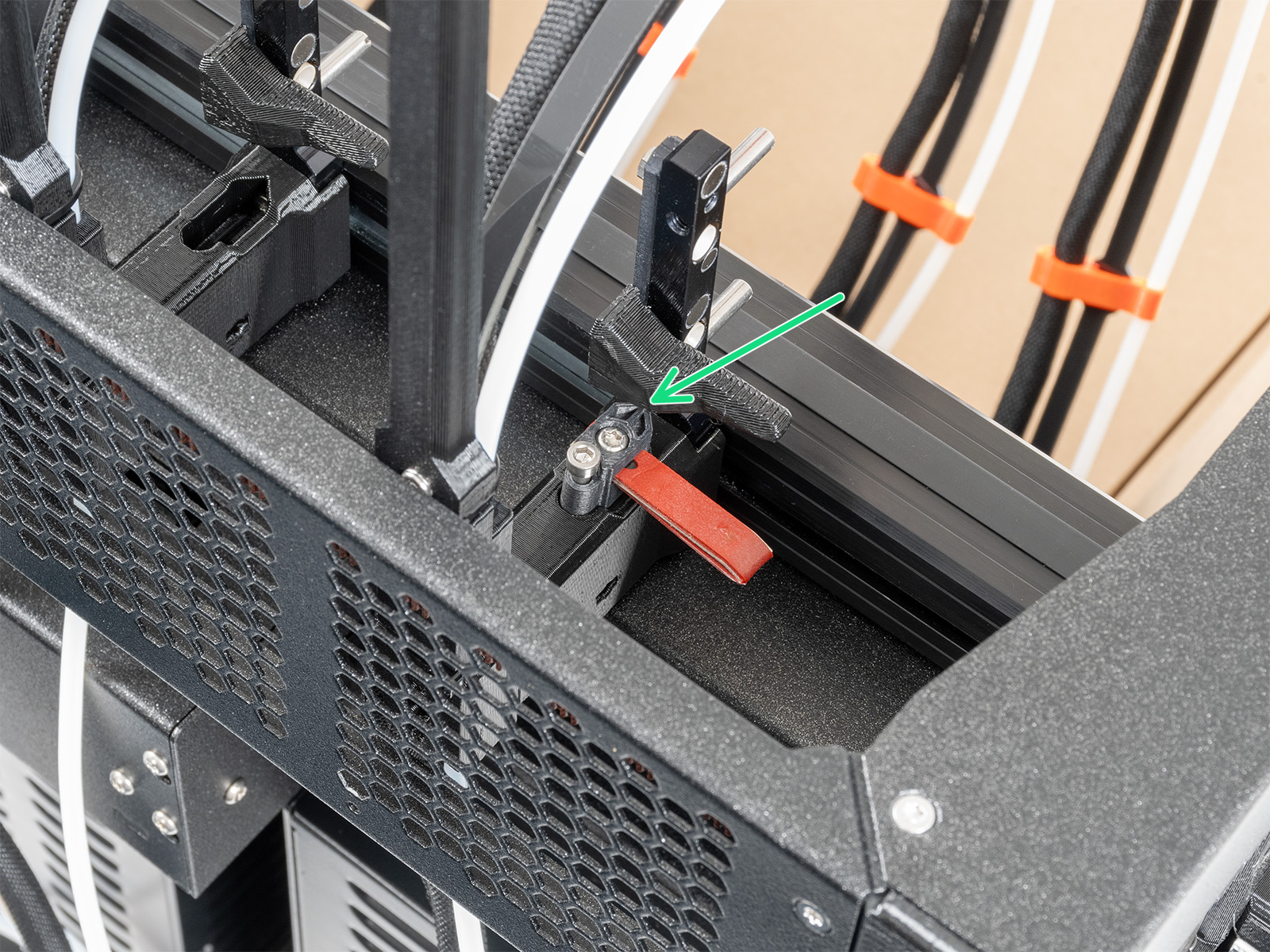
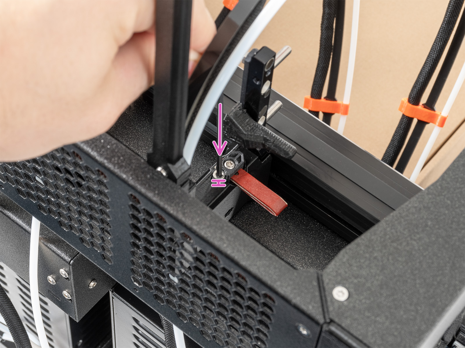
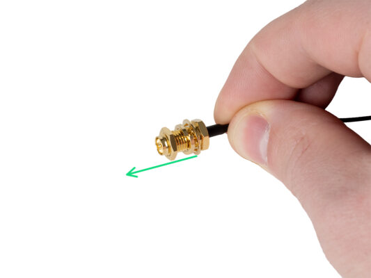
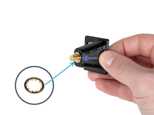
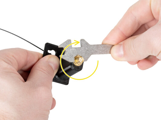
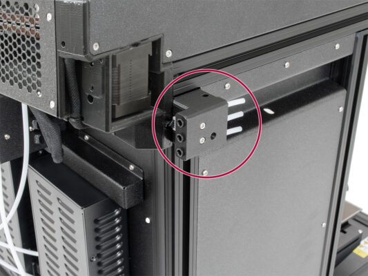
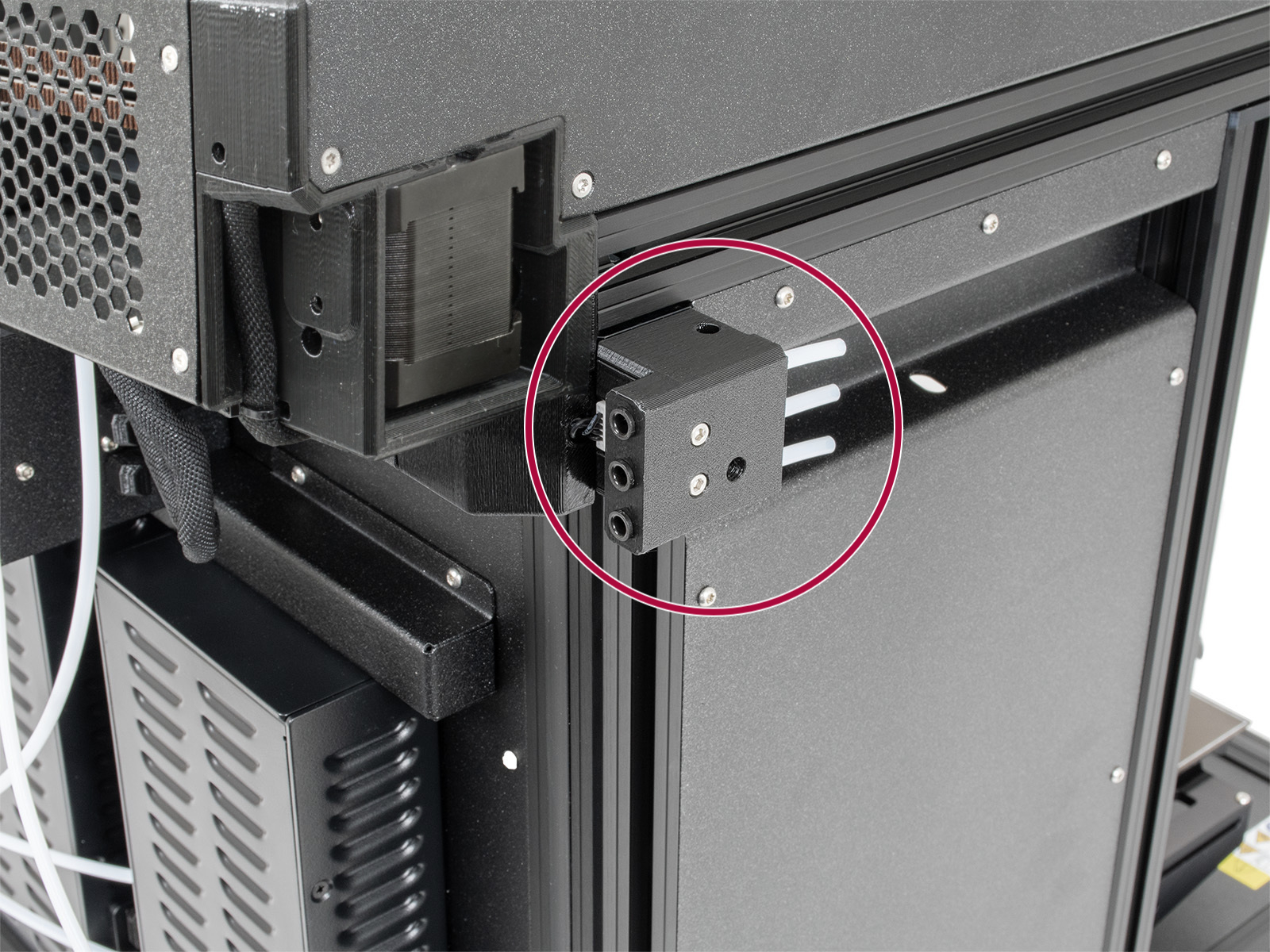
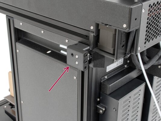
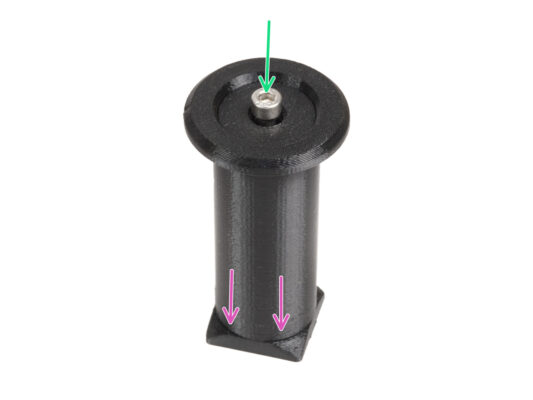
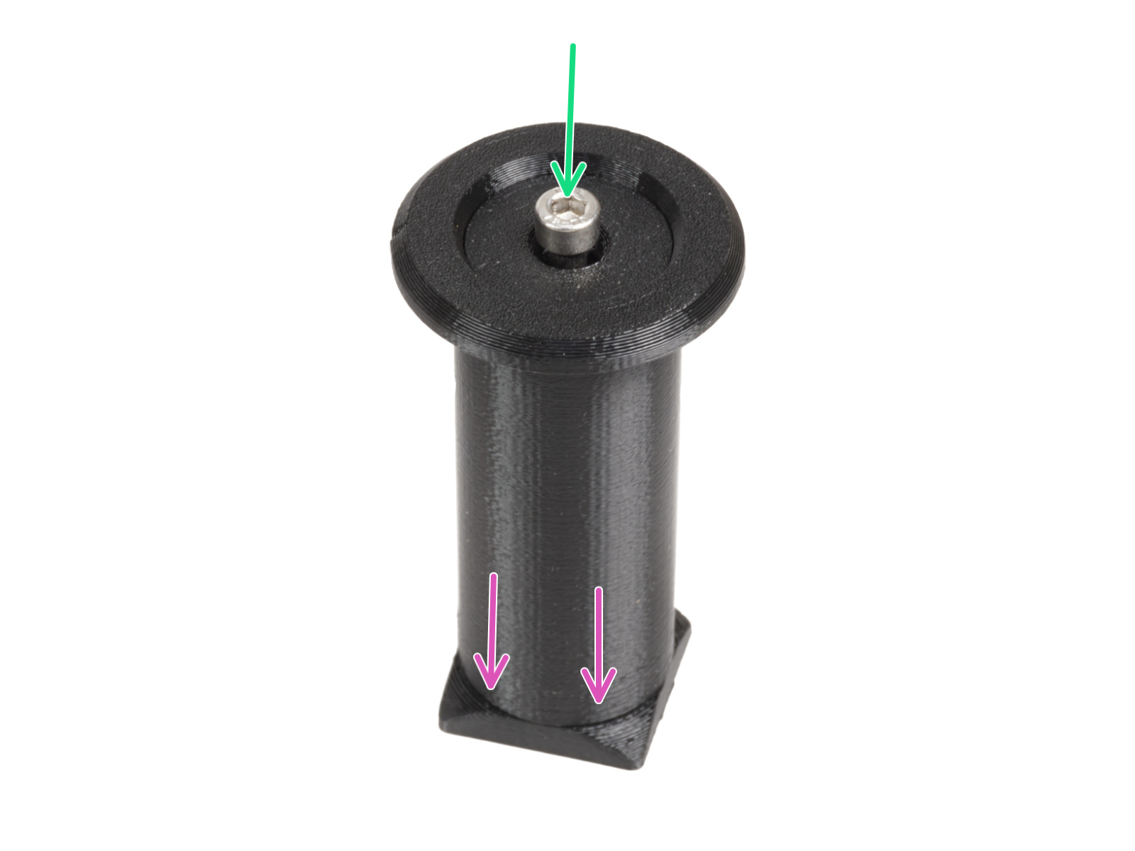
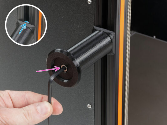
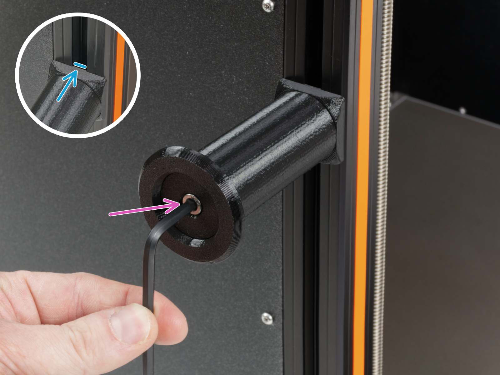
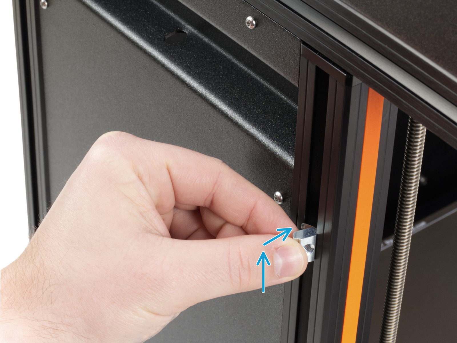
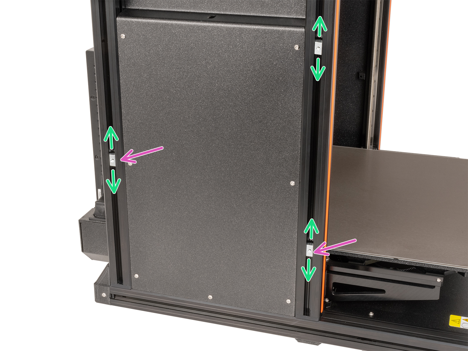
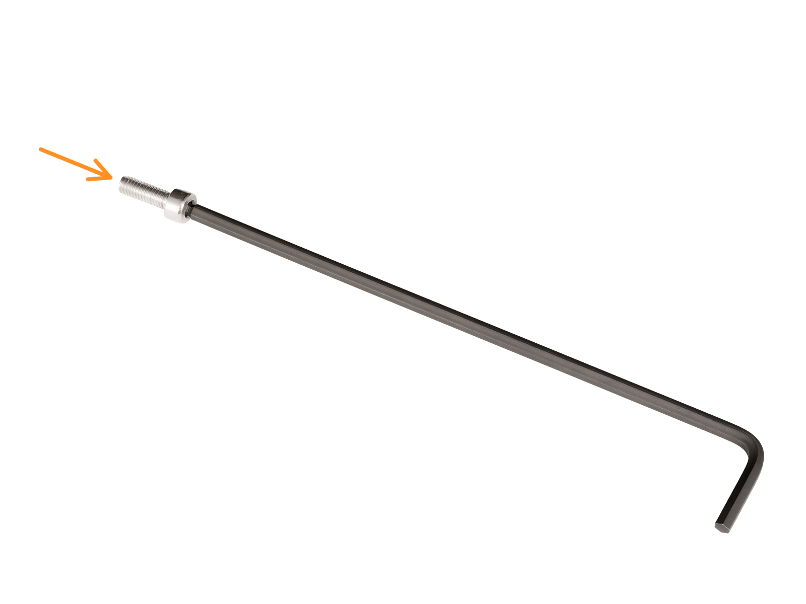
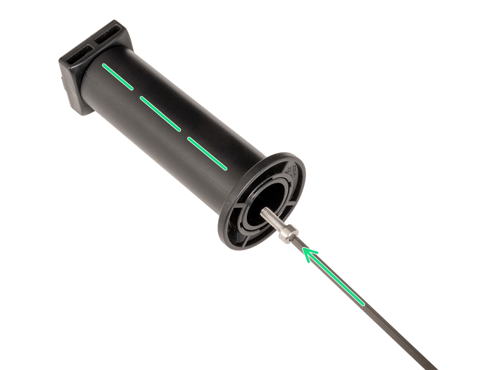
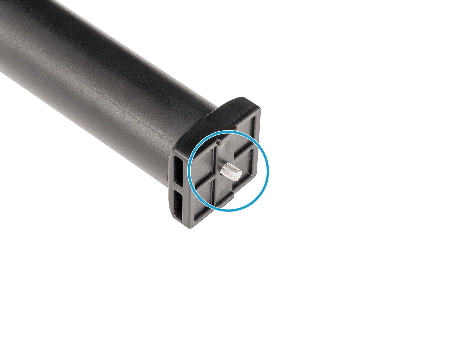
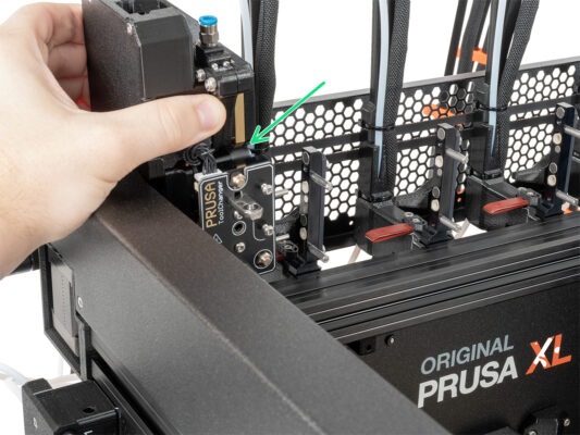
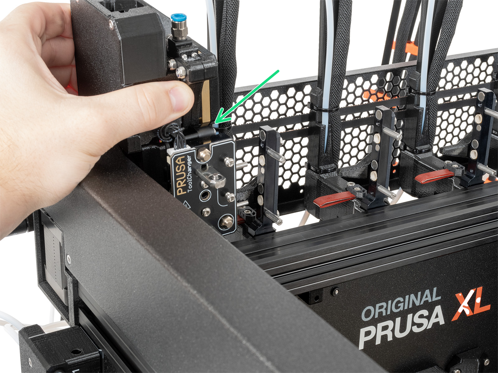
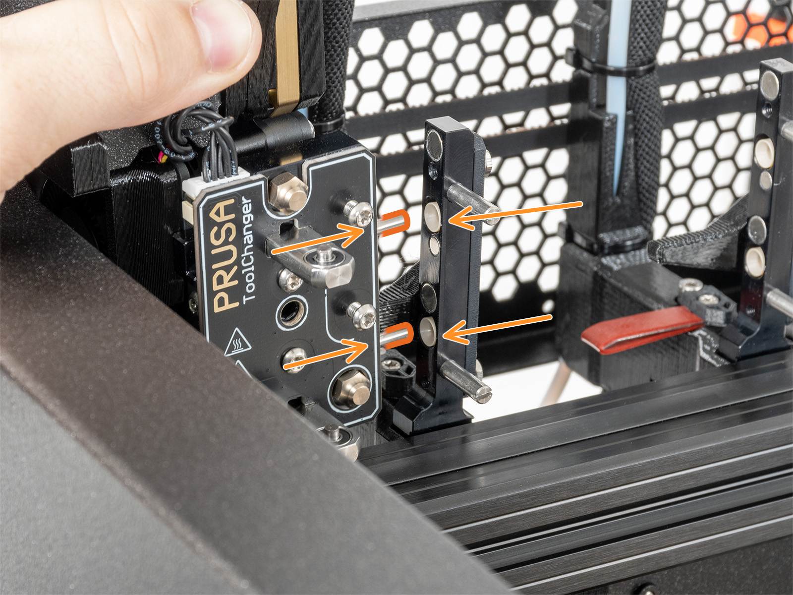
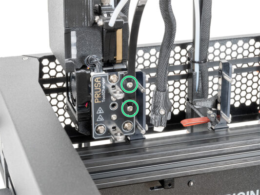
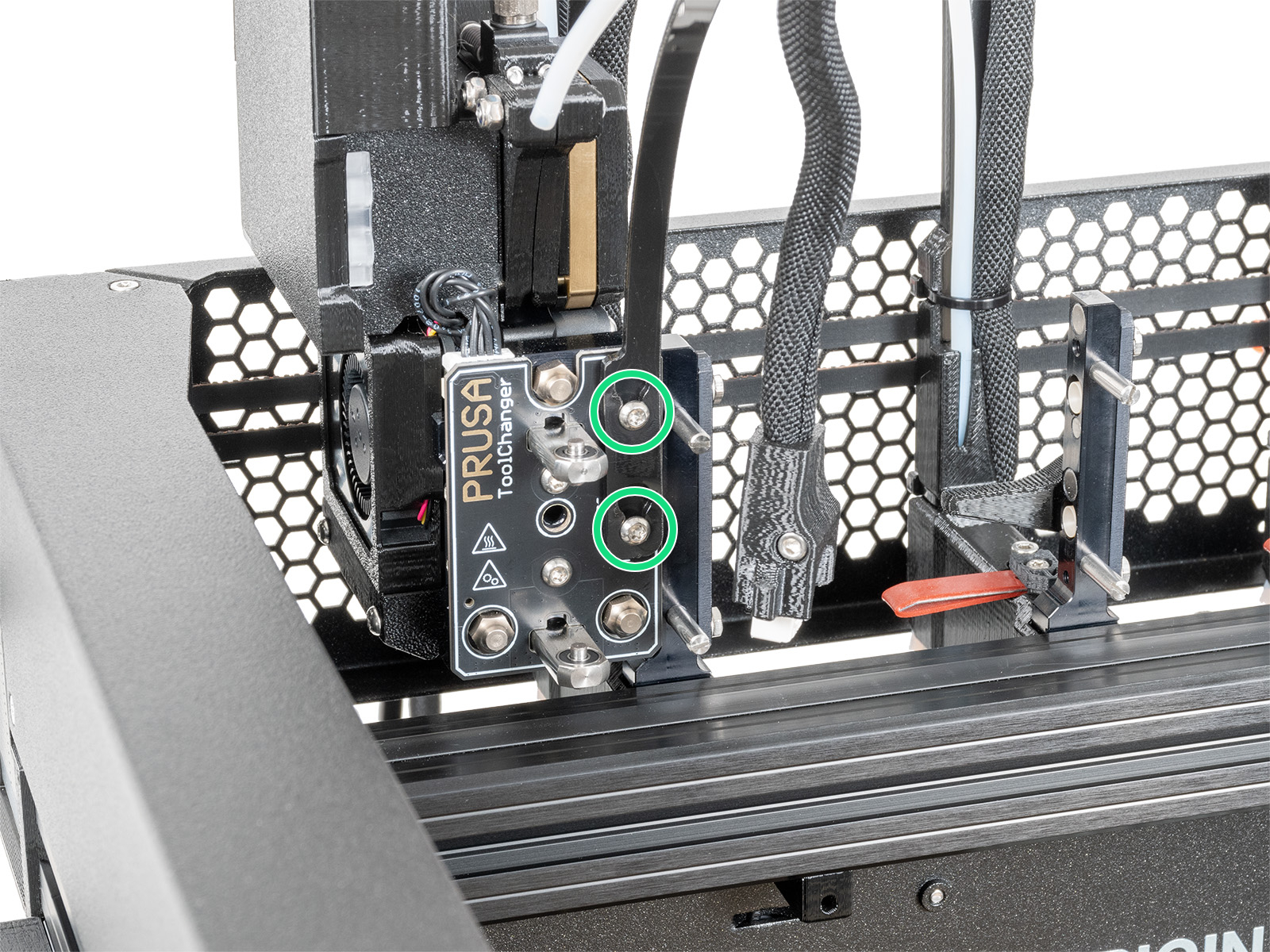
Make sure the nut is pushed into the dock all the way. If not use the Allen key to push the nut into the nextruder dock.

Guiding the Nextruder cable
Carefully turn the printer 180° so that the PSU (Power Supply Unit) side is towards facing you.
Locate the long metal profile with five M3 holes inside the rear aluminum extrusion and slide it all the way to the left side.
We'll use all M3 holes in the metal profile.
Maintain the position of the long metal profile for the next step. It must not move!
Attaching the Nextruder docks
Place the xl-dock-cable-router on the bottom metal sheet below the aluminum extrusion.
There is a protruding screw from the xl-dock-cable-router. Attach the screw to the first screw hole on the long metal profile. Through the hole in the rear metal sheet, check if the cable holder is lined up with the hole.
Push the 2.5 mm Allen key all the way through the hole in the rear metal sheet until you reach the middle screw in the xl-dock-cable-router and tighten the screw.
The dock is a press fit, so the screw needs to be tightened very hard.
Attach all the remaining docks using the same procedure
Dock inspection
Dock inspection
Dock inspection
Check that the docks are properly tightened. The dock must not move. 
The dock is a press fit, so the screw needs to be tightened very hard.
Please watch the video in the next step for a better understanding.
The following instructions need to be done correctly and carefully. Achieve better understanding and successful assembly by watching the video alongside the guide.
Assembling the Nozzle seal
Insert the M3x30 screw into each nozzle seal.
Slide the spring on each nozzle seal.
Do this for all five nozzle seals.
Nextruder nozzle seal
The current nozzle seal position is temporary, the exact height will be set in the next chapter once all the Nextruder parts are mounted.
The docks have a hole for a nozzle seal.
Insert the nozzle seal (with the spring) into the dock.
Using a 2.5 mm Allen key, tighten the screw so that the head of the screw is 1 mm above the dock.
Good! The first dock is ready.
Connecting the nextruder cables
Locate the xl-rear-cable-management-plug (cover) on the rear of the printer.
Loosen two screws on the cover slightly. No need to remove them completely. Push the cover to the right and remove it from the printer.
Loosen four screws securing the electronics cover. Remove the cover.
Connect the #1 dock (from the right side) cable to the upper slot labeled DWARF 1.
Connect the #2 dock (from the right) cable to the lower slot labeled DWARF 2.
Installing the Wi-Fi antenna: antenna preparing
Remove the nut with the washers from the antenna connector.
The antenna connector is prepared.
The latest version of the connector has a thicker washer. We don't need it anymore. You can throw it away.
Insert the antenna connector into the same-shaped hole in the Wi-Fi-antenna-holder .
Installing the Wi-Fi antenna: antenna preparing
Push the antenna connector through the Wi-Fi-antenna-holder.
Insert the thinner washer back onto the connector.
Using the universal wrench, tighten the nut on an antenna connector.
Good job! The Wi-Fi antenna is prepared.
Installing the Wi-Fi antenna holder
Push the antenna cable through the opening in the cable cover (metal sheet) and guide it behind the cover to the electronics box.
Attach the antenna-holder on the screws and push the cover to the left and tighten the screws.
Connect the antenna to the apporpiate slot on the XL Buddy board.
Connecting the Nextruder cables
Do not take the XL-splitter board out of the printer, the photo is only a tool for connecting the Nextruder cables.
Connect the third, fourth and fifth (from the right) Nextruder to the splitter:
#3 Nextruder.
#4 Nextruder.
#5 Nextruder.
XL-splitter with connected Nextruders has to look like this.
XL buddy box covering
Be carefull, do not pinch any cables!
Put the XL-buddy-box-cover back on the printer.
Check Nextruders cables, they have to be inside the cutout in the cover.
With a T10 key tighten the four screws.
Guiding the docks PTFE tubes
Locate the right filament sensor.
Insert the first dock (from the right side) PTFE tube all the way into the upper hole in the part.
Insert the second dock (from the right side) PTFE tube all the way into the middle hole in the part.
Insert the third dock (from the right side) PTFE tube all the way into the lower hole in the part.
Guiding the docks PTFE tubes
Locate the left filament sensor.
Insert the fourth dock (from the right side) PTFE tube all the way into the upper hole in the part.
Insert the fifth dock (from the right side) PTFE tube all the way into the middle hole in the part.
Installing the Wi-Fi antenna
Locate the Wi-Fi antenna connector in the middle of the printer.
Screw the Wi-Fi antenna on the antenna connector. The antenna can be rotated around and bent in two directions.
We recommend pointing the antenna straight upwards.
Spoolholder assembly versions
To make things worse, we have a new spoolholder for you.
Versions:
Version A: Printed spoolholder
If you have this version, continue to the next step.
Version B: Injection molded spoolholder
If you have this version, continue to the step 32.
Version A: Spool holder: left side
Carefully turn the printer so that the side with the Filament sensor (with 3 PTFE tubes) facing you.
Insert the M5nEs nut into the front support extrusion (with the orange plastic cover). Insert the side with the spring (metal plate) first, then push the nut inside.
The M5nEs nut is free to move, you can adjust the position as you want. But remember, the nut must be slightly pushed in to smoothly move. Anyway, we recommend approximately the same position as you can see in the picture.
Insert the second and third M5nEs nut in the extrusion approximately to the same position as shown.
Version A: Assembling the spool holder
Repeat this step for all five spool holders:
Insert the spool-holder-base into the spool-holder-slider and push it through a little through the part.
Attach the spool-holder to the spool-holder-mount.
Insert the M5x85 screw into the spool-holder-assembly.
Version A: Mounting the spool holder assembly
Attach the spool holder assembly to the M5nEs nut in the extrusion. Note that there is a protrusion on the spool-holder-mount, which must fit into the groove in the extrusion.
Tighten the spool holder assembly with a 4 mm Allen key.
Attach and tighten the second and the third spool holder to the M5nEs nut using a 4 mm Allen key.
Do not use the spool holder as a handle!
Keep in mind that if you mount the Spool holder too high or too low, it may not fit the filament spool on it. There has to be enough space around it.
Version A: Spool holder: right side assembly
Carefully turn the printer so that the side without the Wi-Fi antenna faces you.
Insert the fourth and fifth M5nEs nut in the extrusion approximately to the same position as shown.
Attach and tighten the fourth and the fifth spool holder to the M5nEs nut using a 4 mm Allen key.
Do not use the spool holder as a handle!
Keep in mind that if you mount the Spool holder too high or too low, it may not fit the filament spool on it. There has to be enough space around it.
Version B: Assembling the spool holder: adjusting the nut
Carefully turn the printer so that the side with the side filament sensor is facing you.
Insert the first M4nEs nut into the front support extrusion (with the orange plastic cover). Insert the side with the spring (metal plate) first, then push the nut inside.
Insert the second and the third M4nEs nut into the extrusions as described in the picture.
The M4nEs nuts are free to move, you can adjust the position as you want. But remember, the nuts must be slightly pushed in to smoothly move. Anyway, we recommend approximately the same position as you can see in the picture.
Version B: Assembling the spool holder
Locate pins two pins on the spool-holder-base and line them with the rails in the spool-holder-slider.
Insert the spool-holder-base into the spool-holder-slider and push it through a little through the part.
Version B: Preparing the spool holder
Insert the M4x12 screw on the longer side of the 3mm Allen key.
Insert the 3mm Allen key with the M4x12 screw through the assembled spool holder to the prepared hole in the spool-holder-base.
The M4x12 screw has to protrude through the spool-holder-base.
Version B: Spool holder: left side assembly
Attach the first spool holder assembly to the M4nEs nut in the extrusion. Note that there is a protrusion on the spool-holder-mount, which must fit into the groove in the extrusion.
Tighten the spool holder assembly.
Assemble the second and the third spool holder and attach them to the M4nEs nuts with M4x12 screws.
Do not use the spool holder as a handle!
Version B: Spool holder: right side assembly
Turn the printer, so the Filament sensor (with two PTFE tubes) is facing you.
Insert the fourth and fifth M4nEs nut in the extrusion approximately to the same position as shown.
Attach and tighten the fourth and the fifth spool holder to the M4nEs nut using a 3 mm Allen key.
Do not use the spool holder as a handle!
Keep in mind that if you mount the Spool holder too high or too low, it may not fit the filament spool on it. There has to be enough space around it.
Haribo time!
Haribo time!
Take three gummy bears and share the rest of the gummy bears with the people who helped you build the 3D printer.
Did you know that gummy bears are loved by people of all ages, from children to adults, and are often enjoyed as a nostalgic treat?
How to dock the Nextruder
Take the Nextruder and place it carefully next to the dock.
Place the two metal inserts through the white holes in the dock. The magnets will help you dock the Nextruder.
Check that the Nozzle seal lightly touches the nozzle.
Well done, the first Nextruder is ready!
Connect the second, third, fourth and fifth Nextruder in the same way as the first.
Nextruder cable bundle assembly
Repeat this step for all tool heads:
Take the first dock Nextruder cable bundle.
Check that the cable bundle is not twisted!
Hook up the keyhole openings in the flexible plate of the cable bundle onto the screw heads and push it up to correct the position.
Using a T10 key tighten the marked two screws.
Nextruder cable bundle assembly
Repeat this step for all tool heads:
Attach the cable connector into the top of the Nextruder.

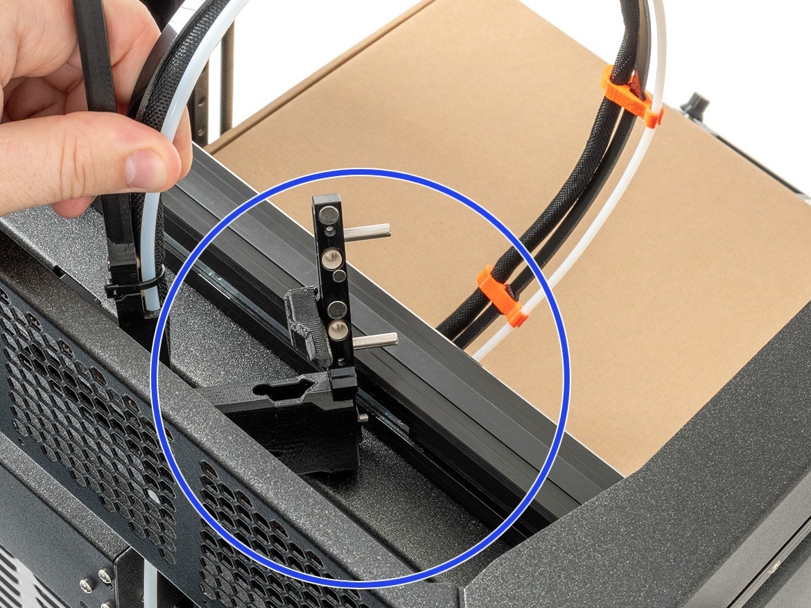
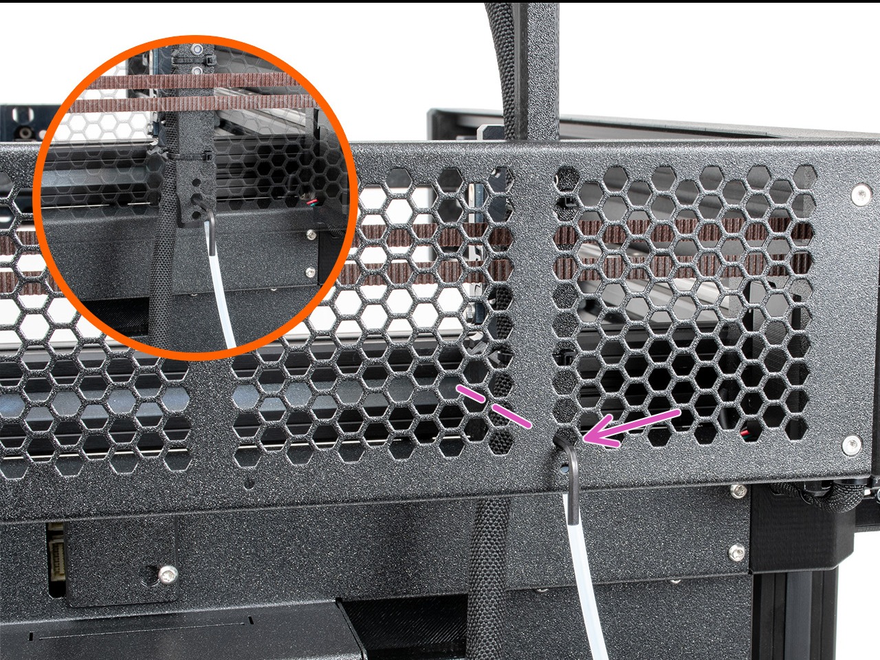
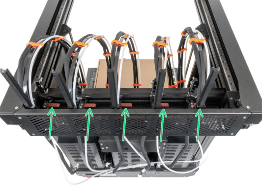
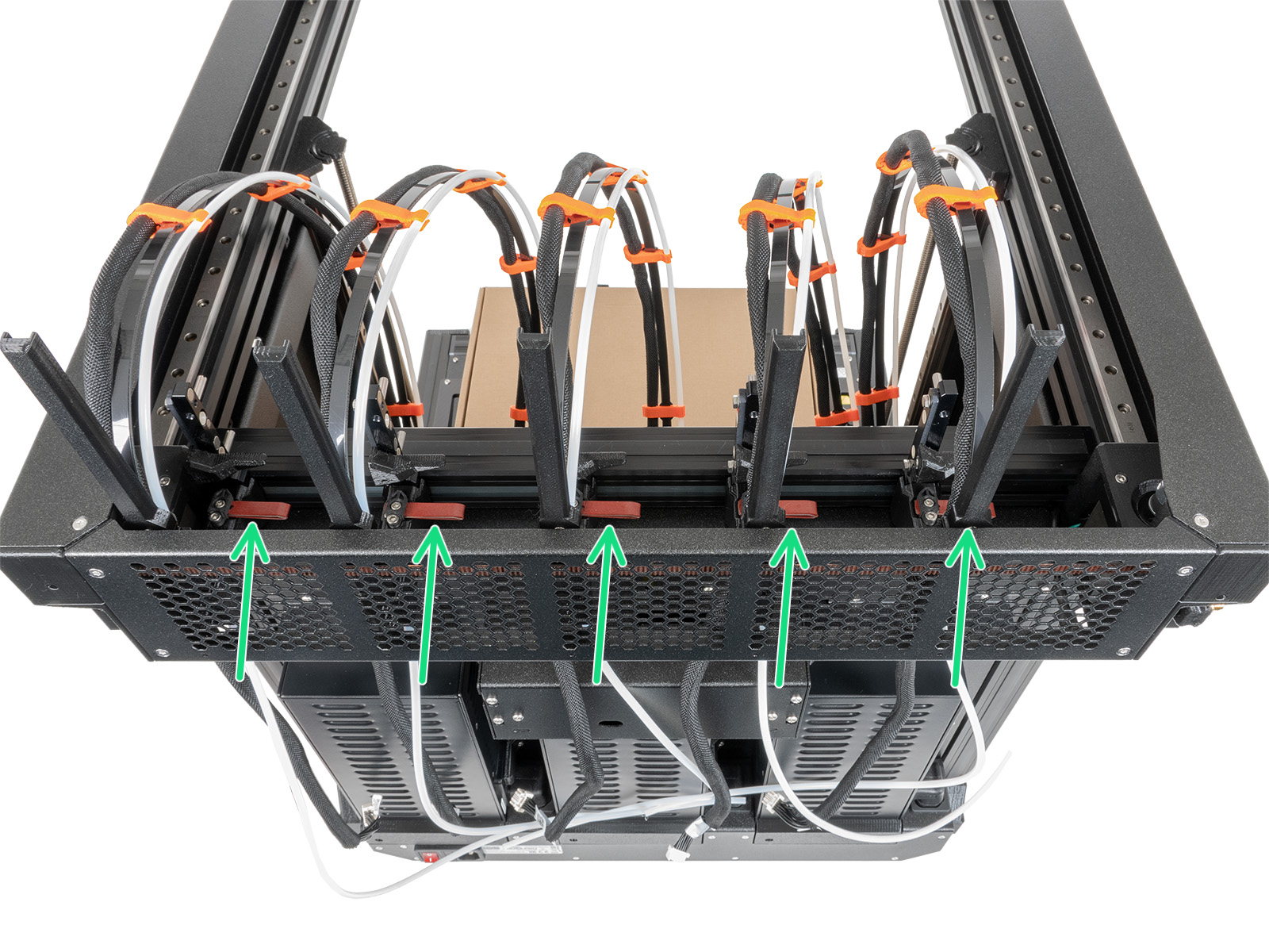
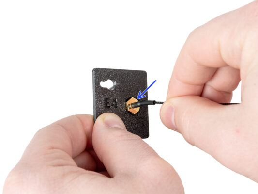
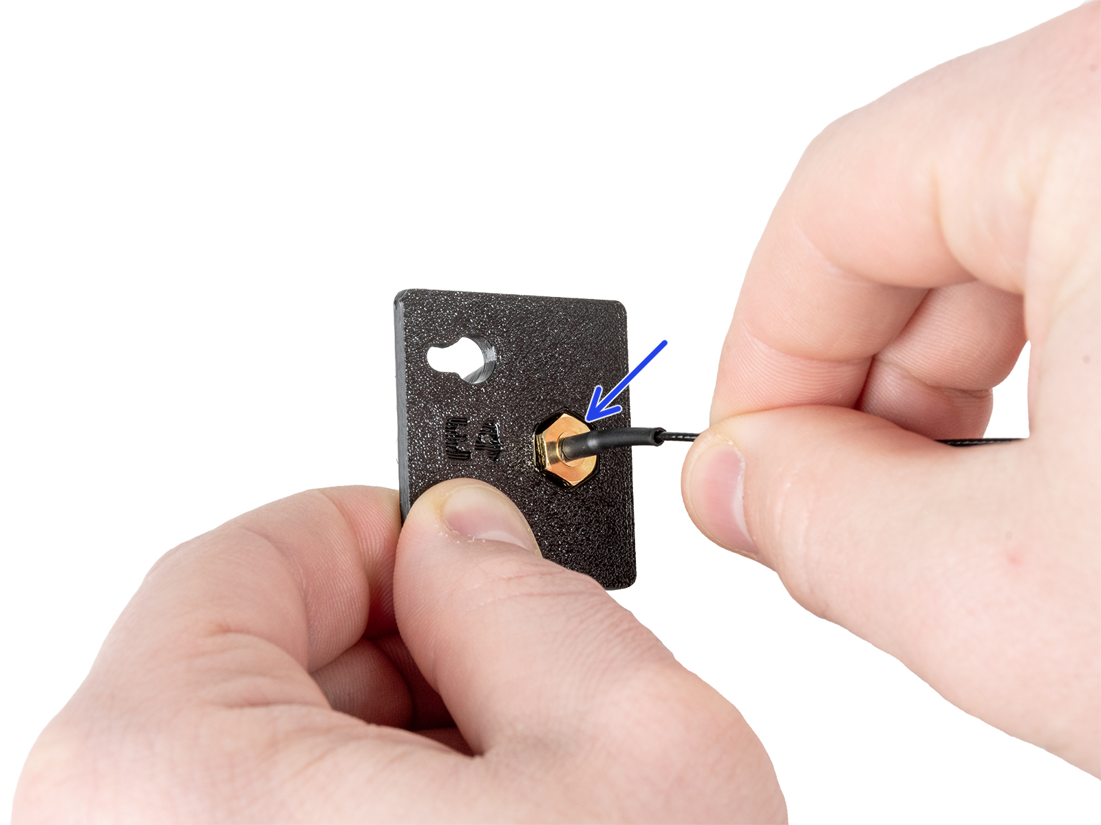
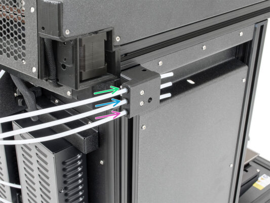
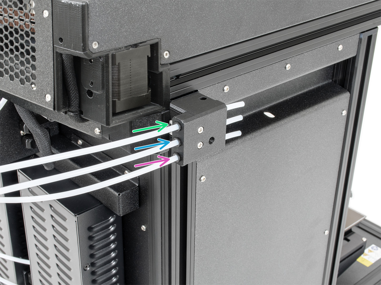
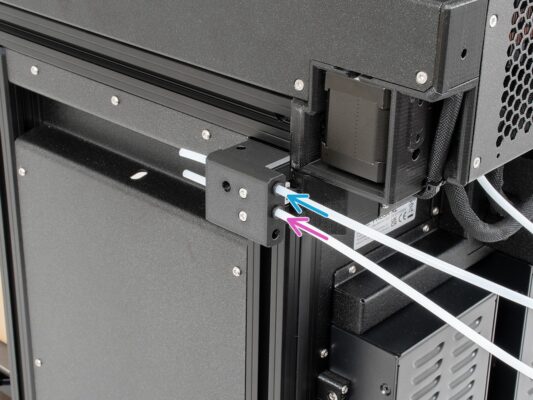
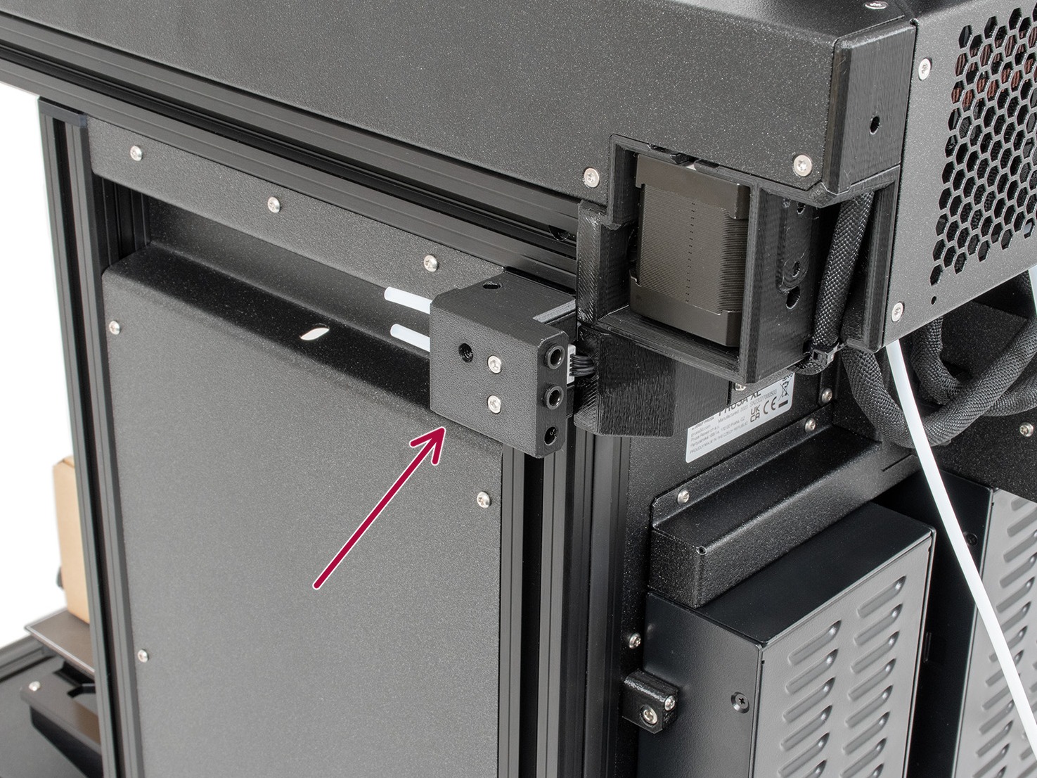
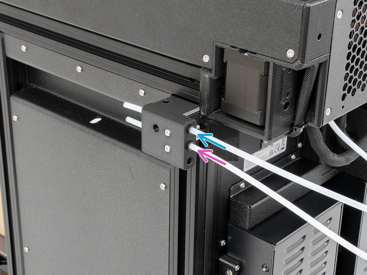
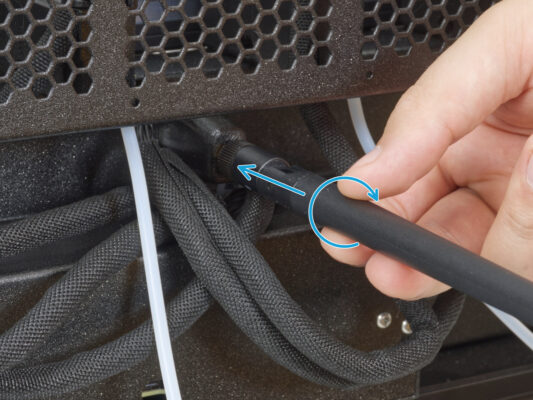
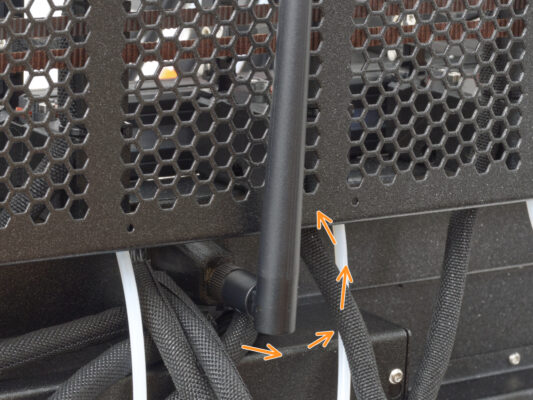
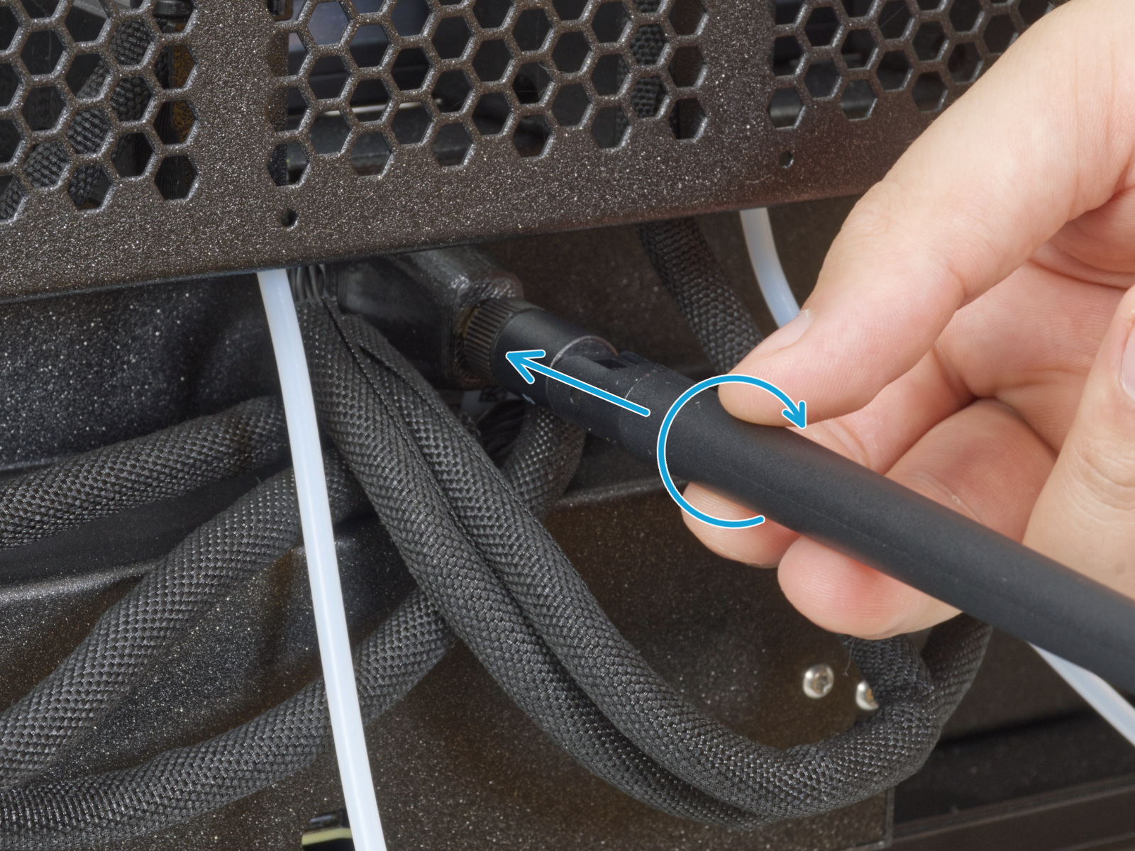
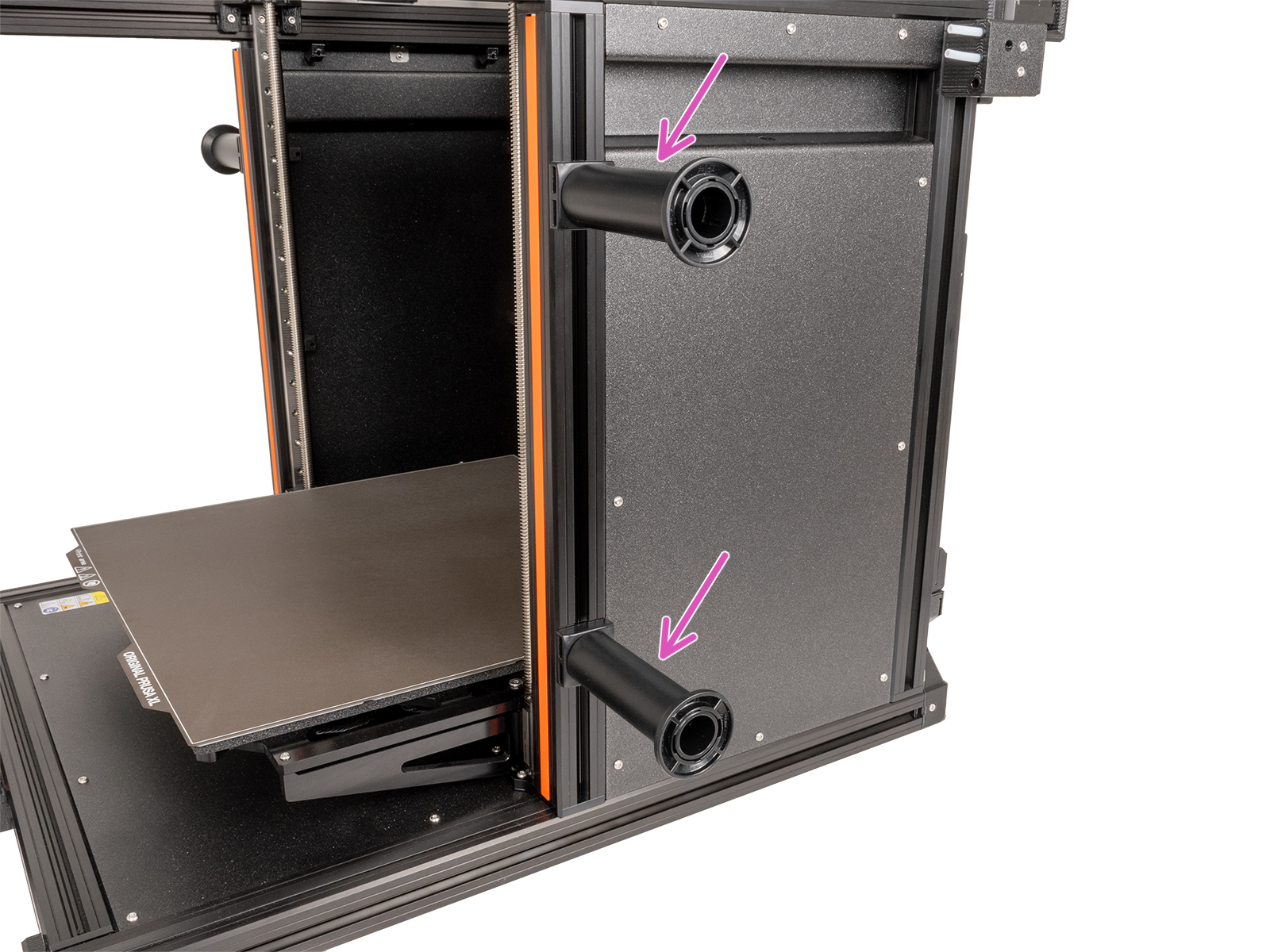
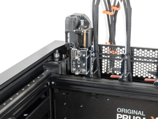
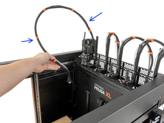
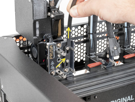
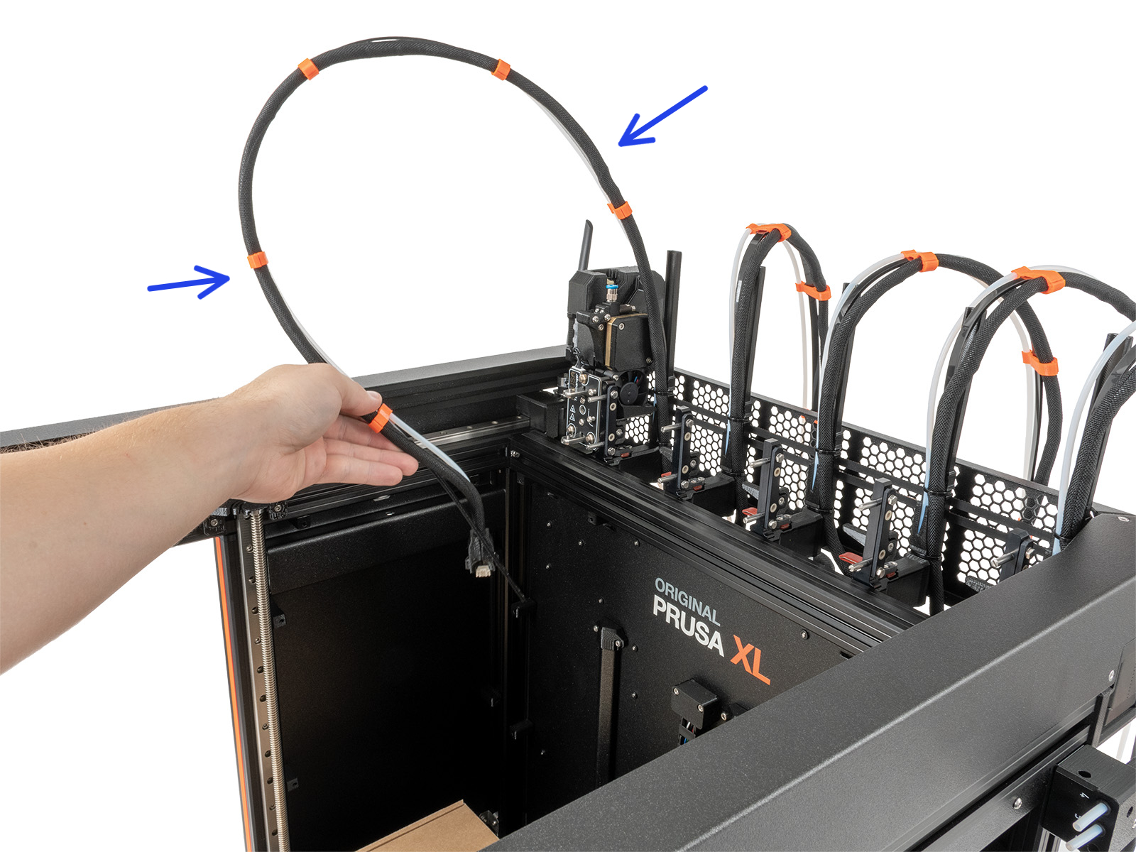
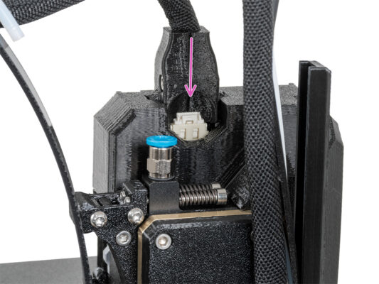
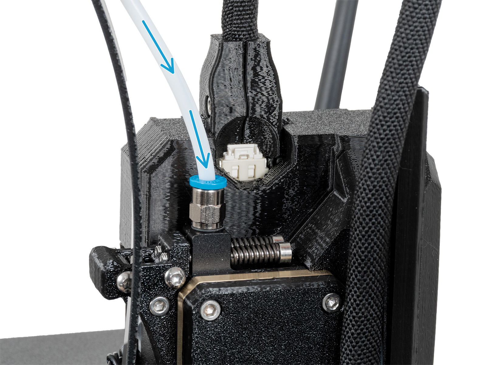
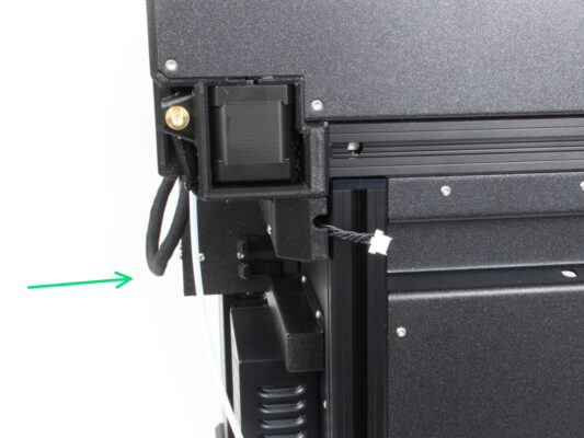
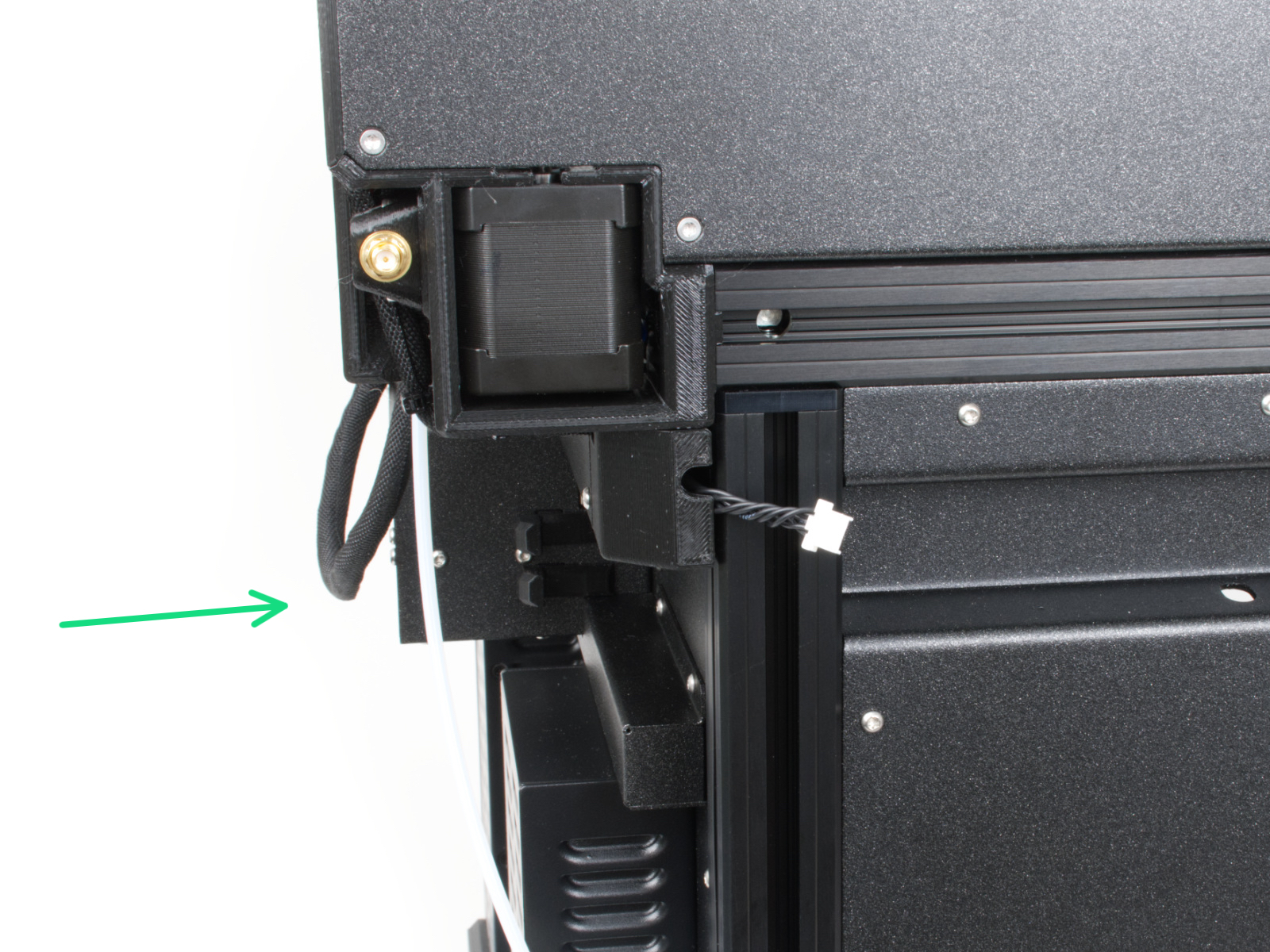
Insert the semi-transparent PTFE tube into the FESTO fitting on the Nextruder. Push it all the way in.

Assemble and connect all Nextruders.
Good job!
Almost done!
Almost done!
Congratulation! Your Original Prusa XL is ready to be fired up!
Compare the final look with the picture.
Now, let's go to the last chapter 7. First run.
Was this guide helpful?

Comments

Still have questions?

Still have questions?

If you have a question about something that isn't covered here, check out our additional resources.
And if that doesn't do the trick, you can send an inquiry to [email protected] or through the button below.

Contact us