⬢For this chapter, please prepare:
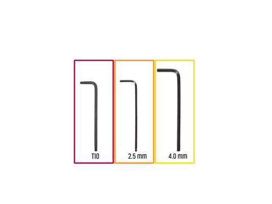
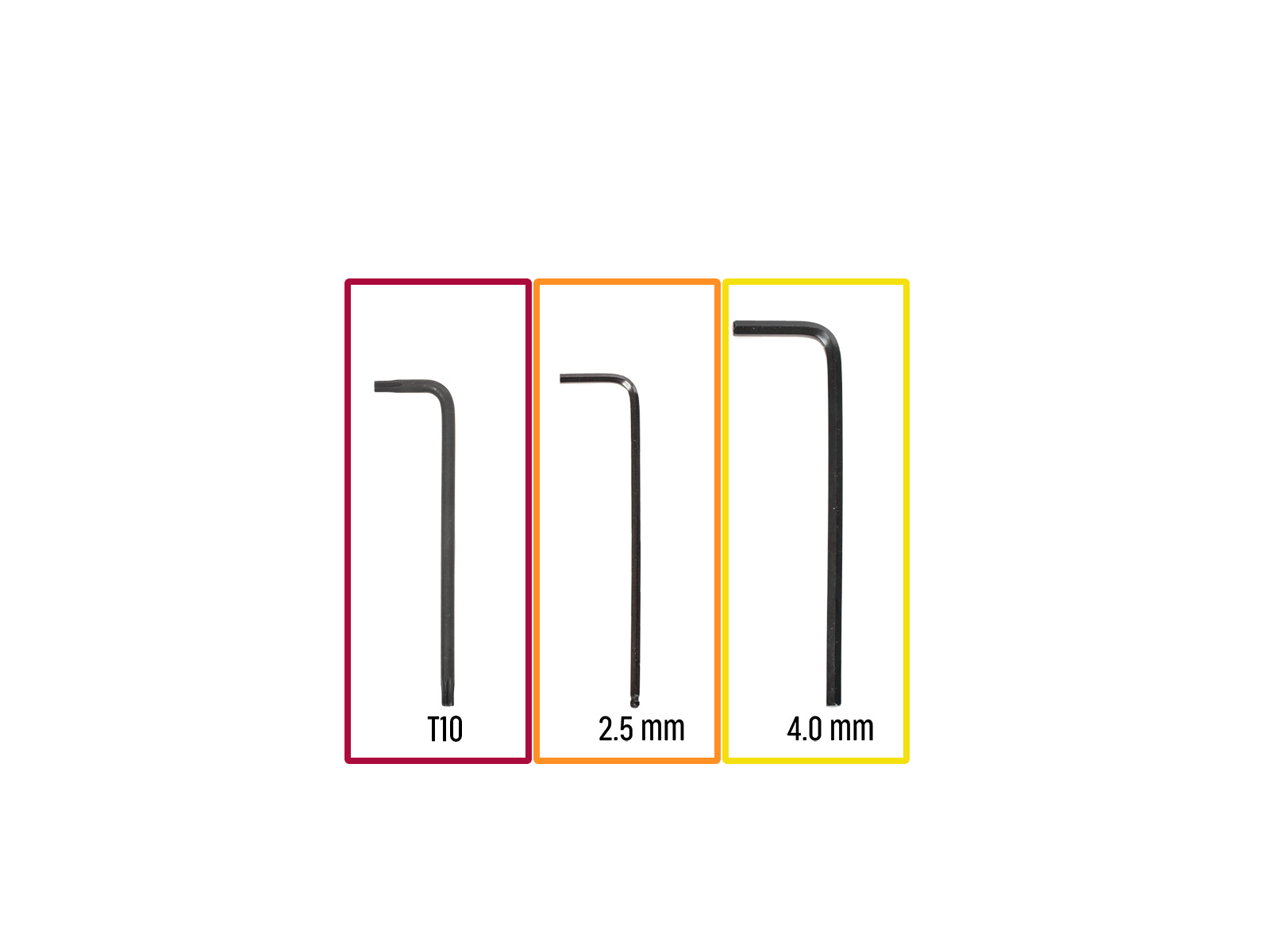
⬢T10 Torx key
⬢2.5 mm Allen key
⬢4.0 mm Allen key
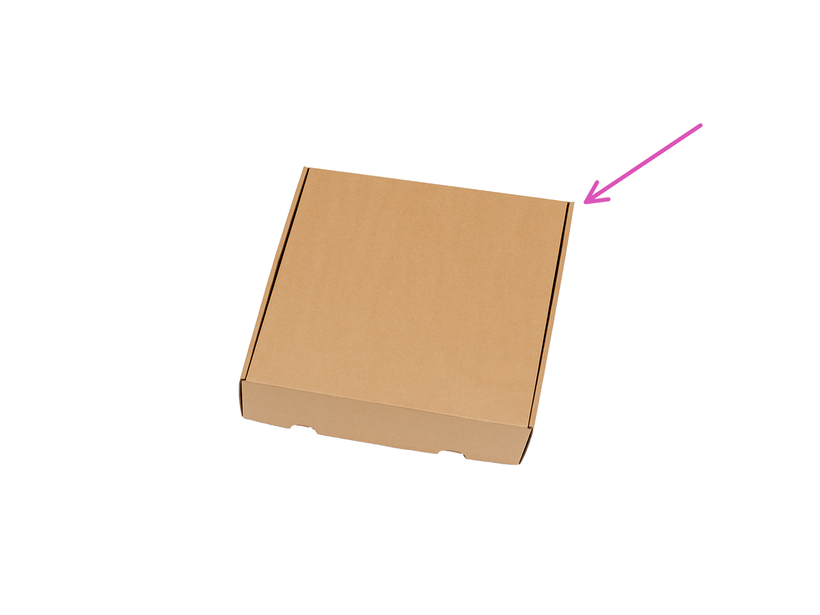
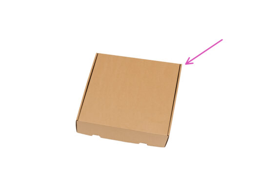
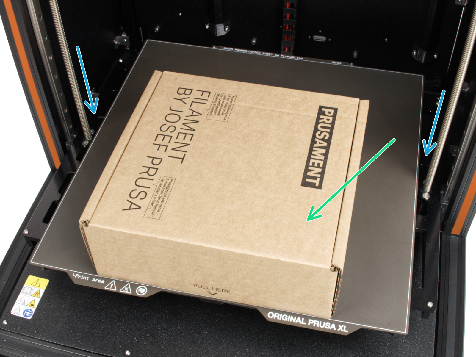
⬢A cardboard box is to be used as heatbed protection during the setup. Hint: you can use the Nextruder box shipped with your printer.


If you have a question about something that isn't covered here, check out our additional resources.
And if that doesn't do the trick, you can send an inquiry to [email protected] or through the button below.

