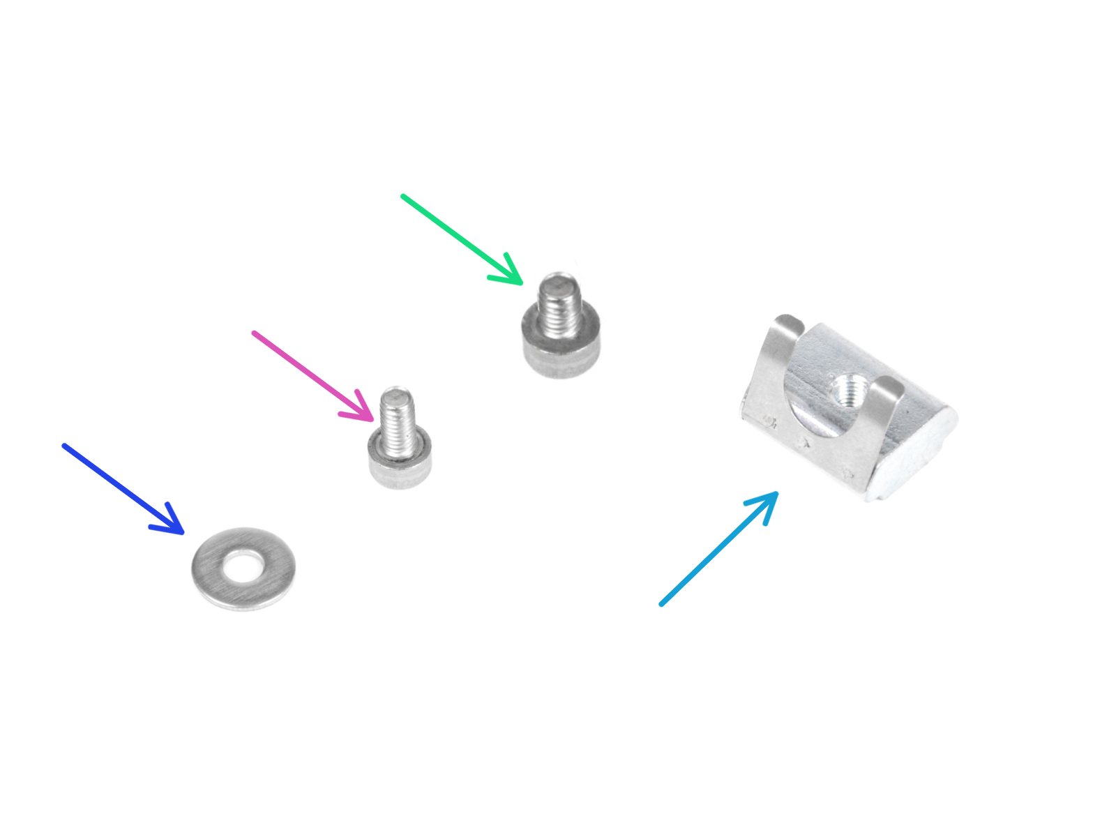
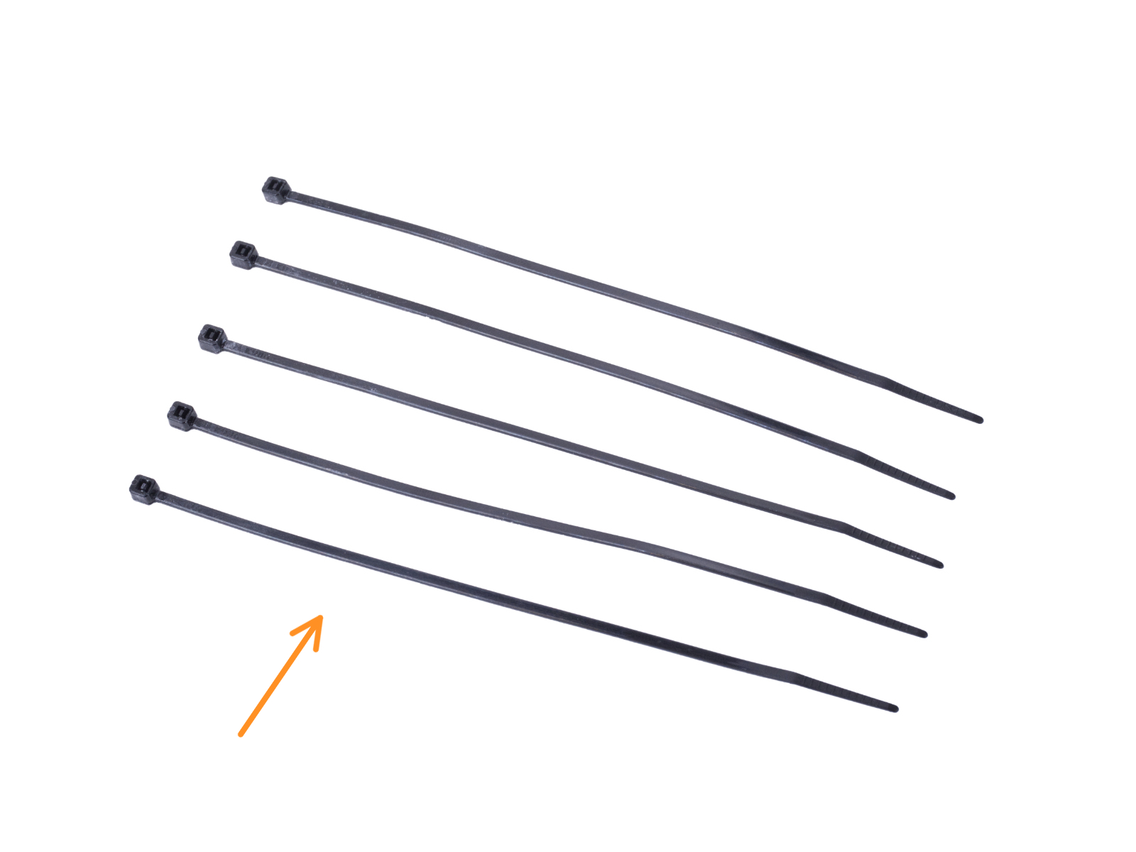
⬢For the following steps, please prepare:
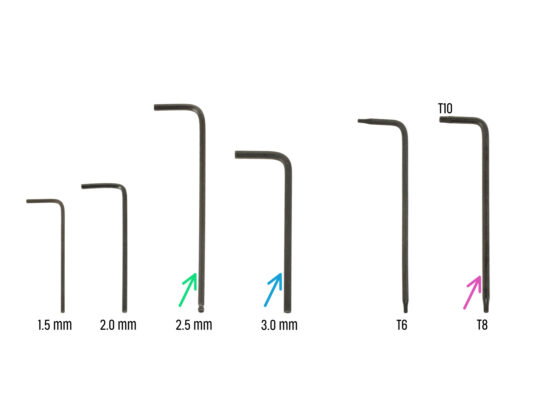
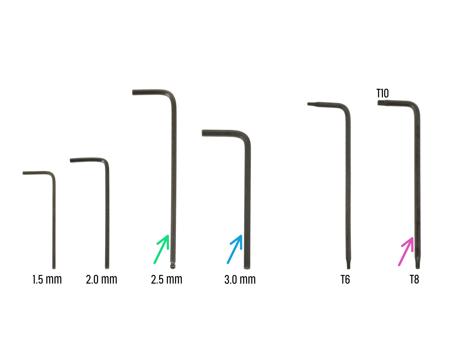
⬢2.5mm Allen key
⬢3.0mm Allen key for silver PSU version
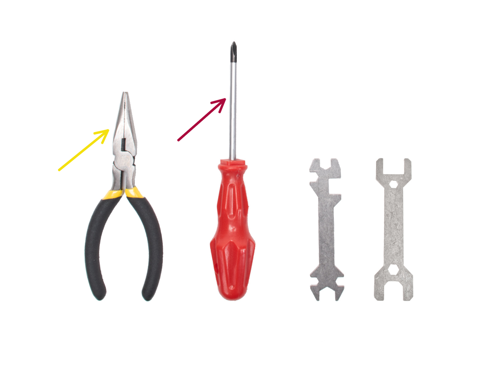
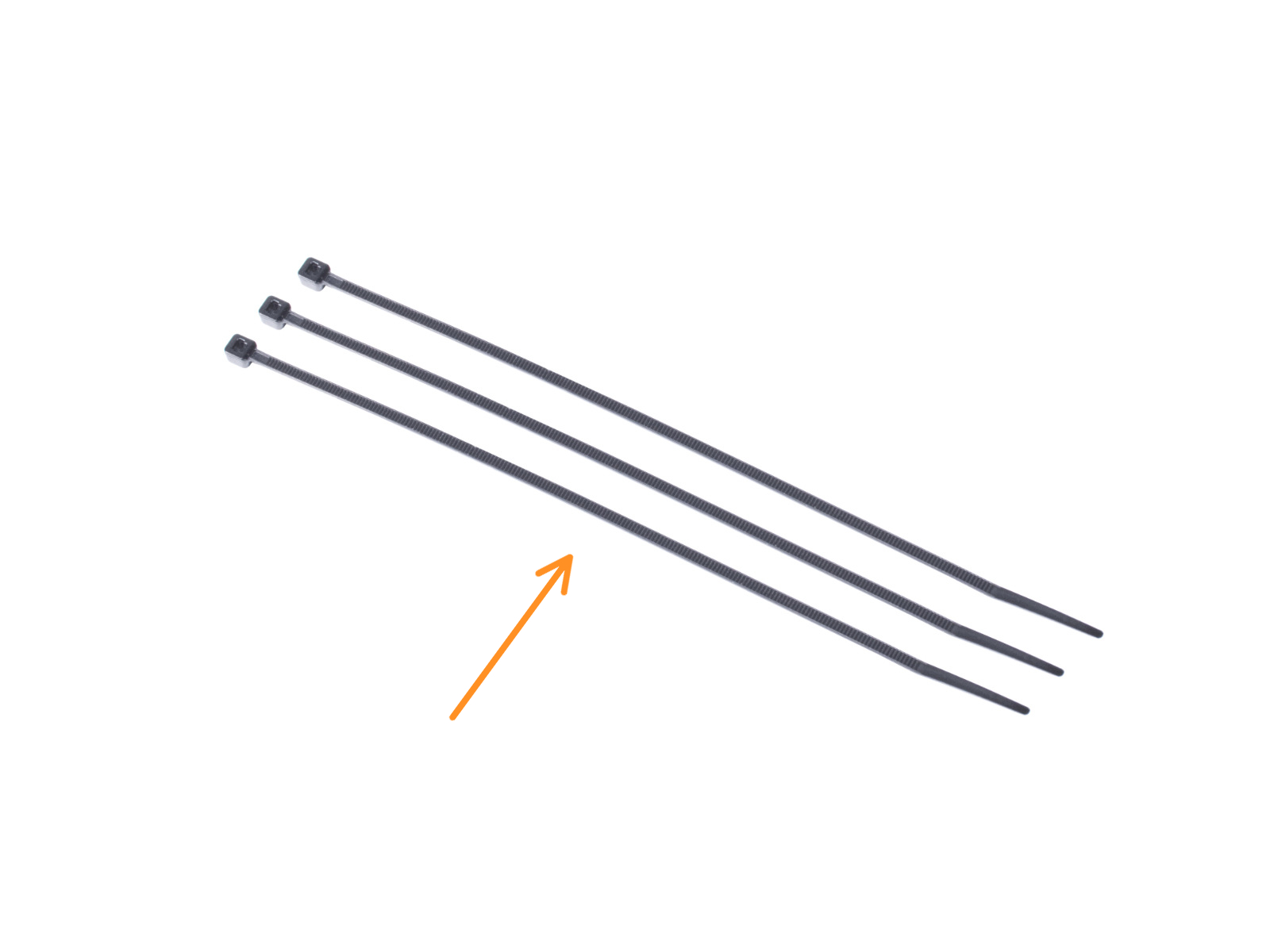
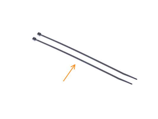
⬢Needle-nose pliers for tightening and cutting zip ties
⬢Torx key T8/10
⬢Phillips screwdriver


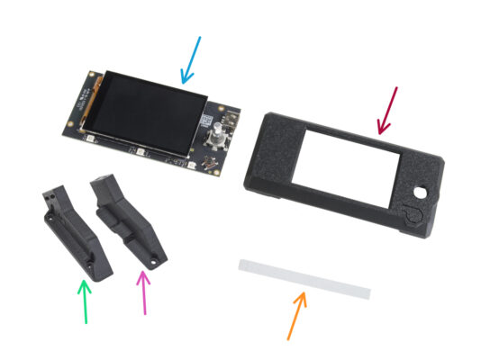
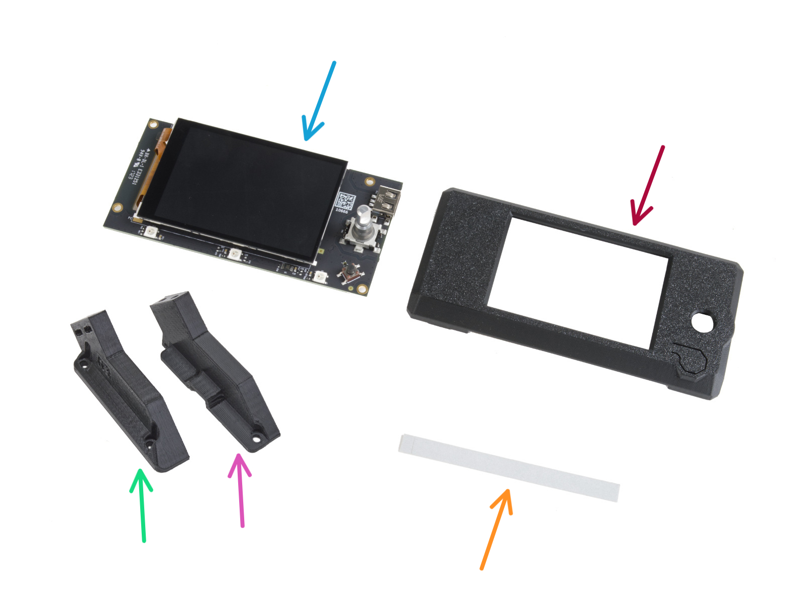


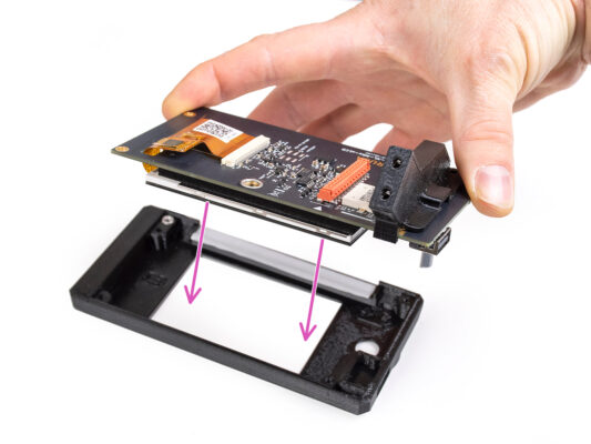
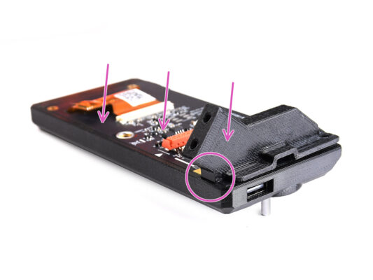
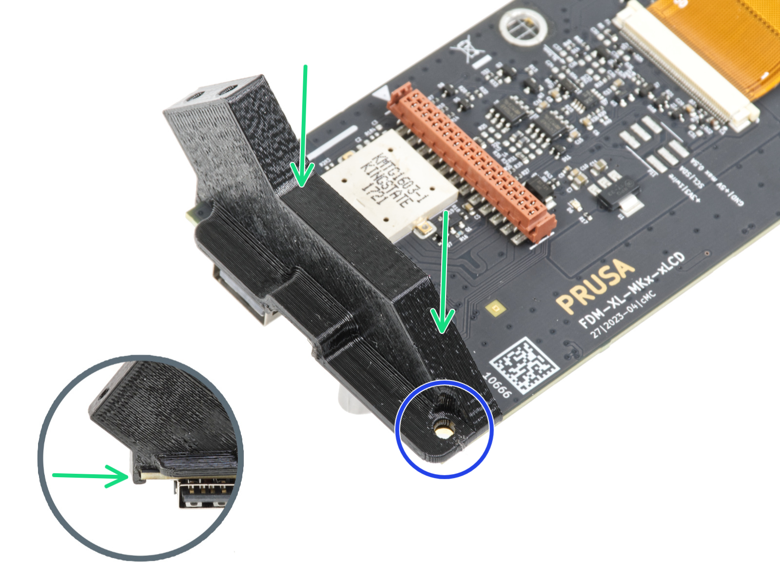


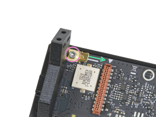
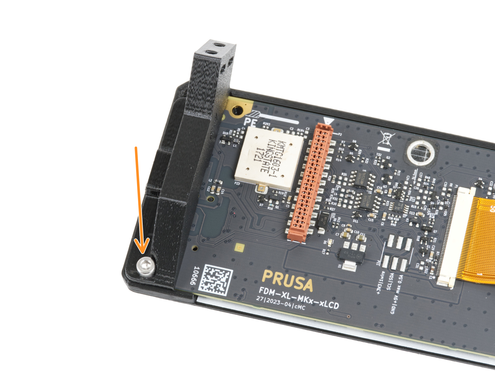

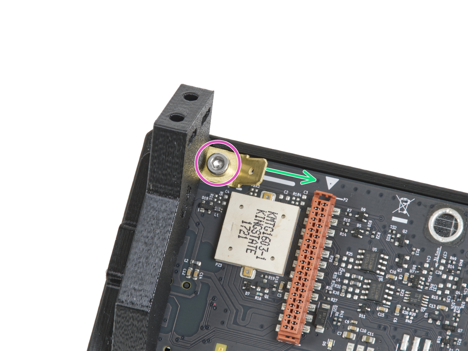


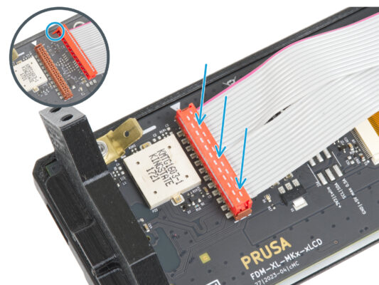
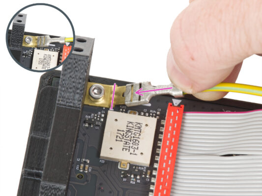

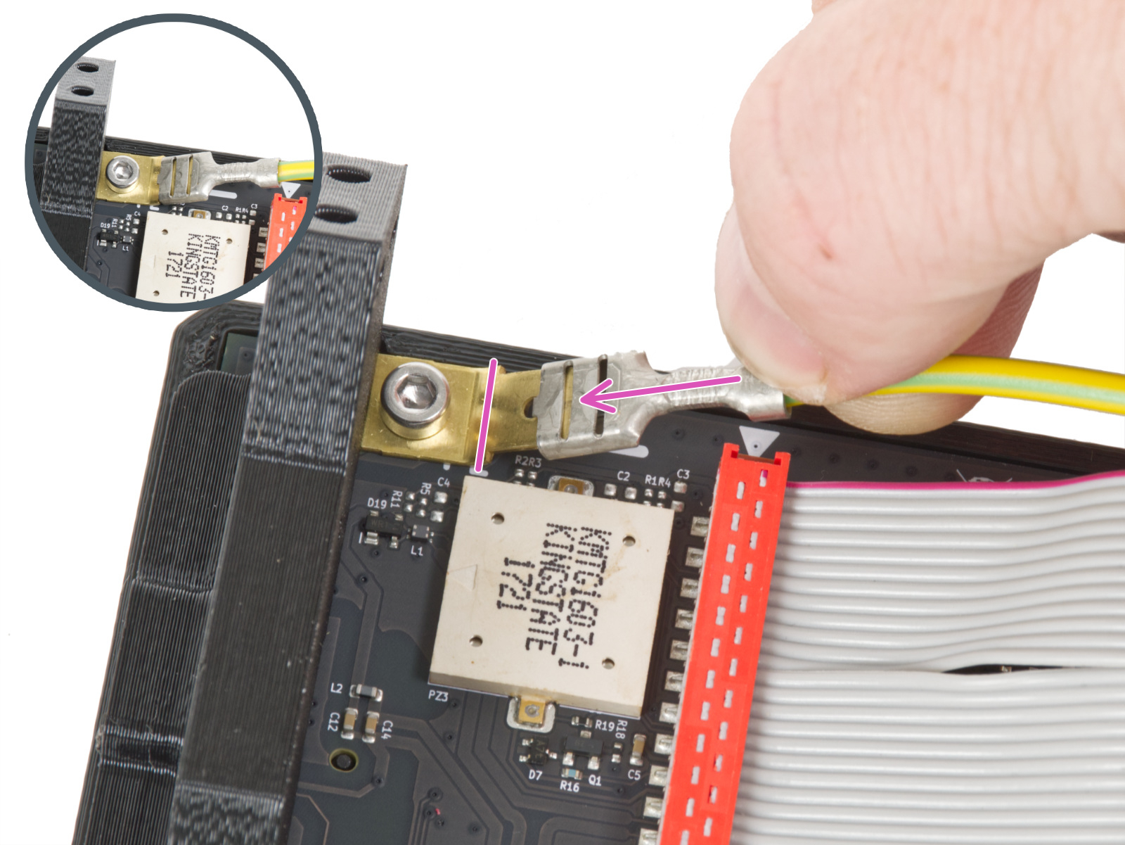

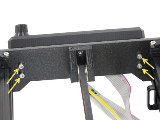

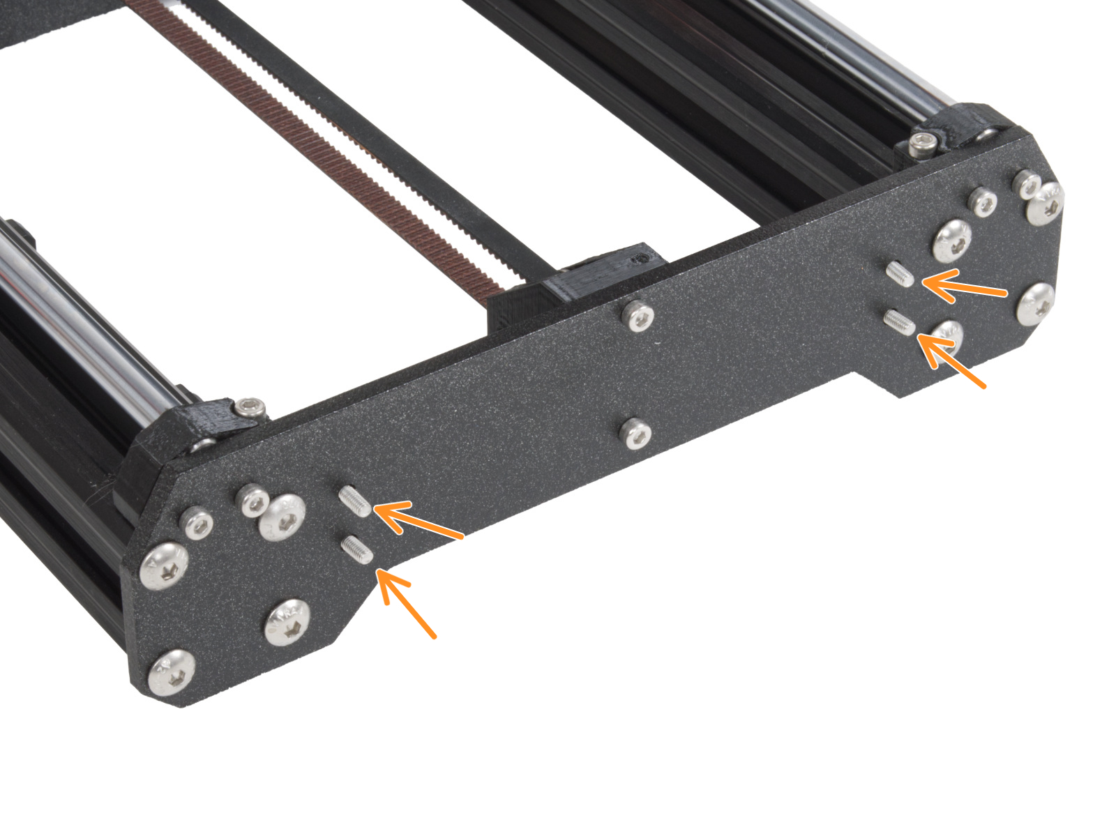
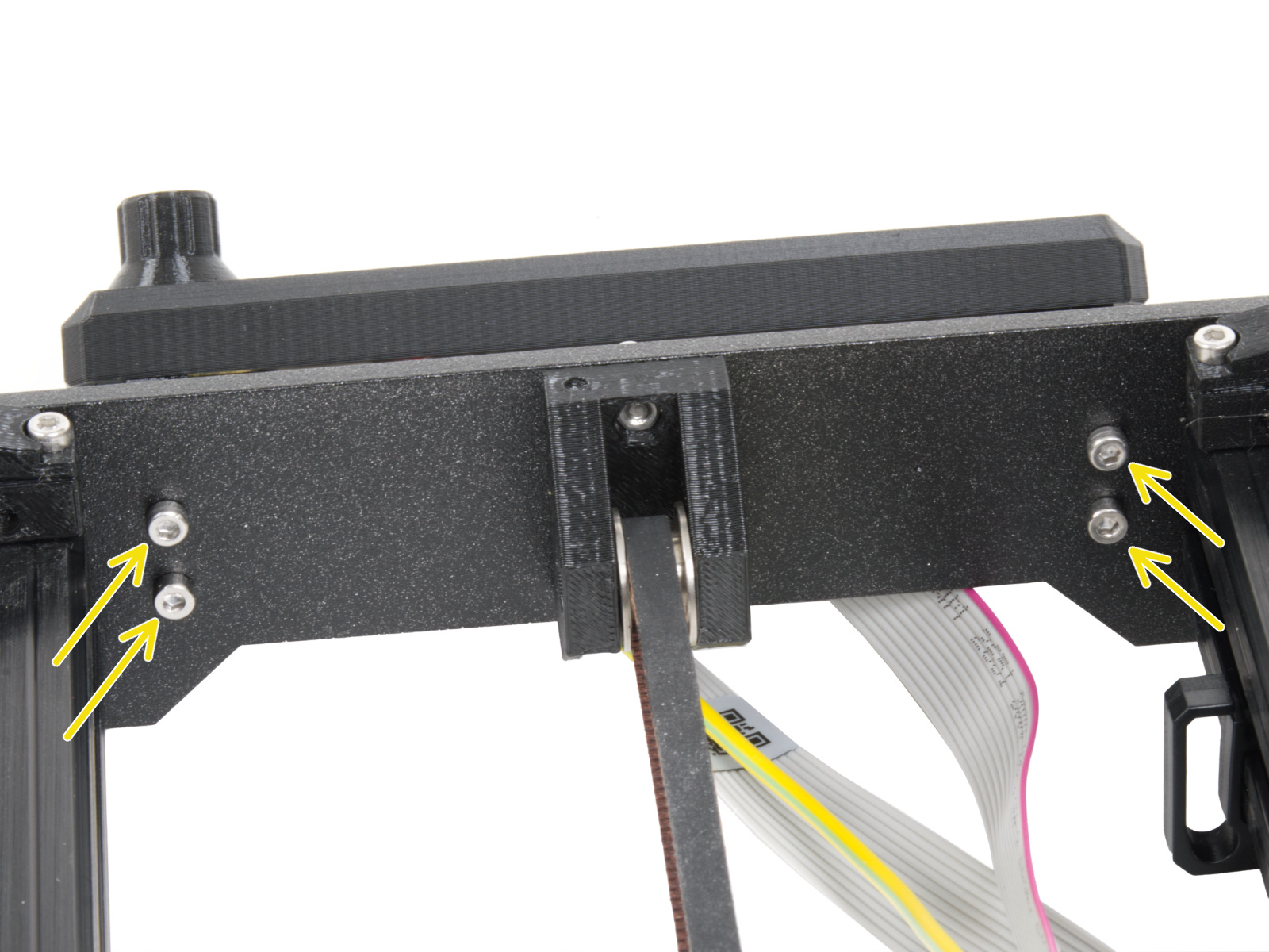
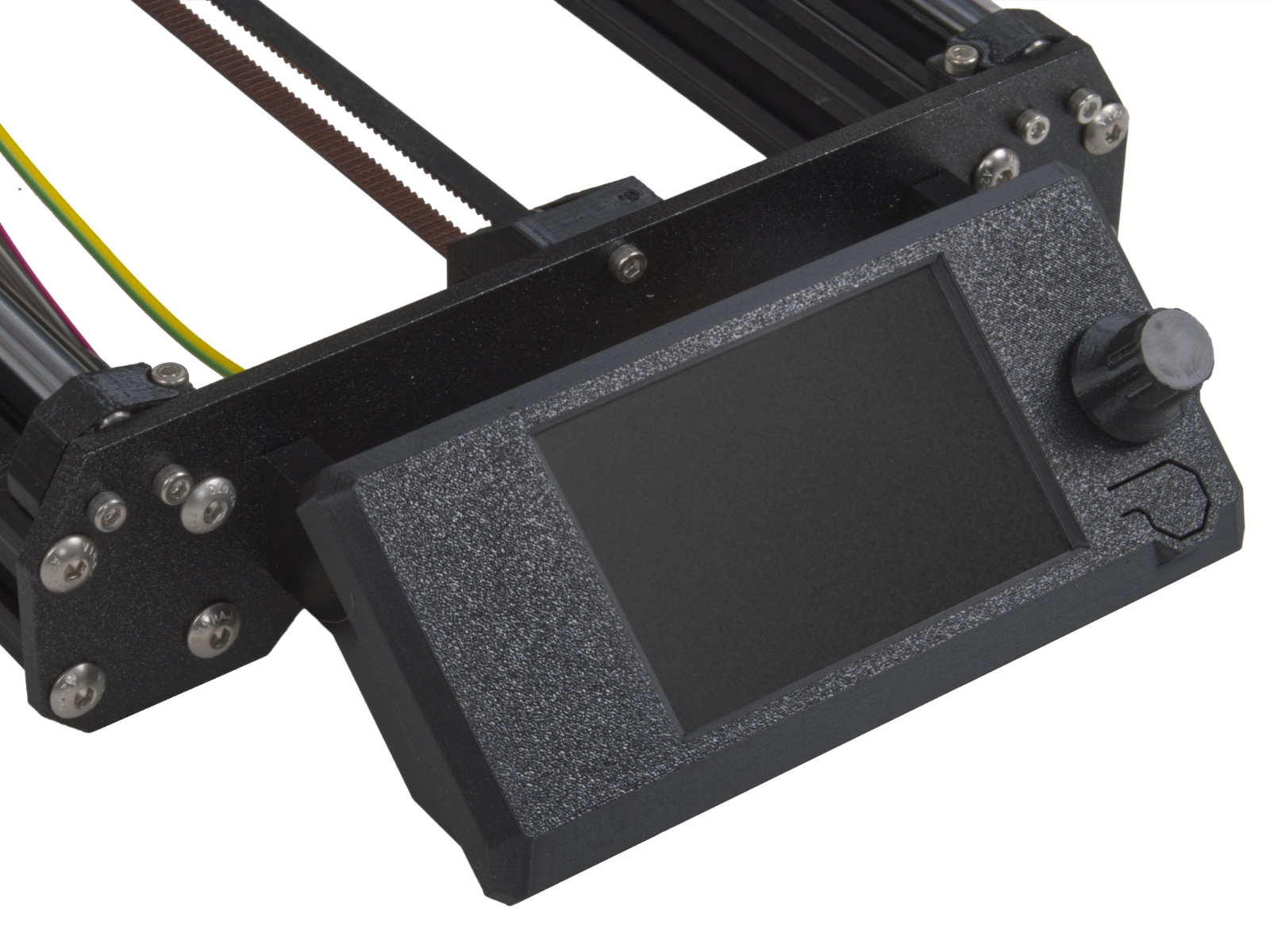
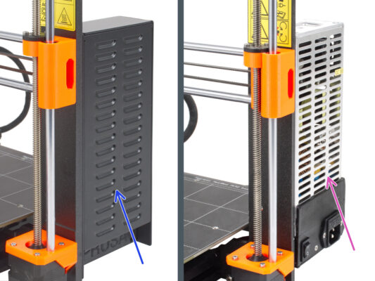
Attach the xLCD assembly onto the front plate. The screws should fit into the corresponding openings in the xLCD assembly.
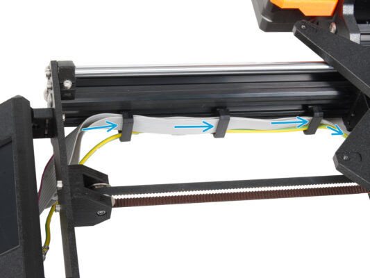


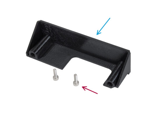
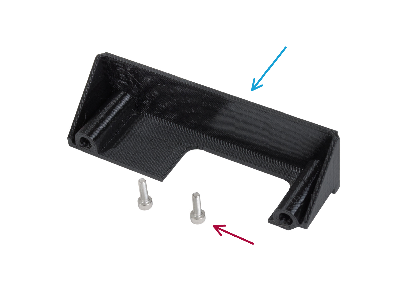


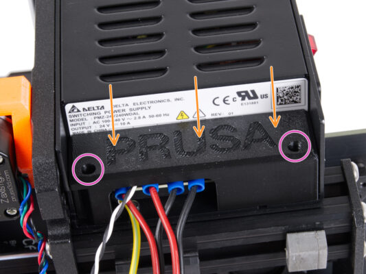


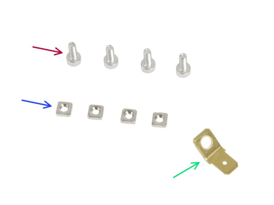
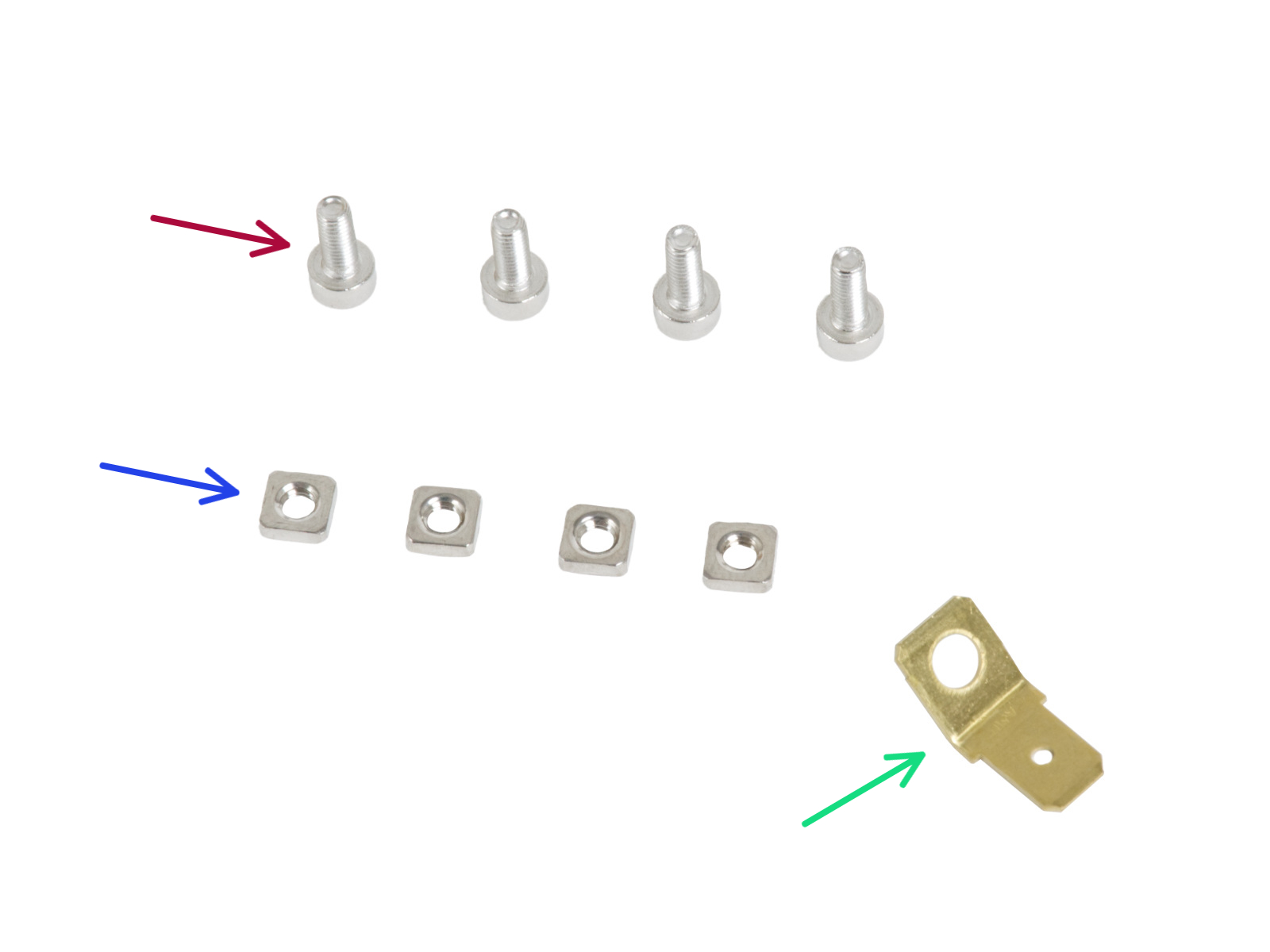
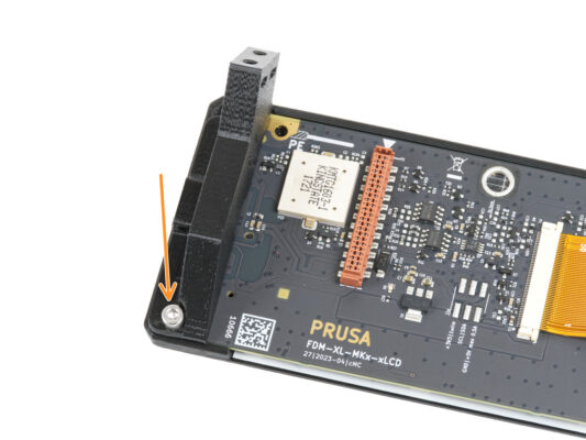
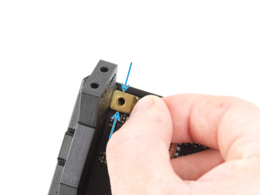
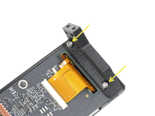
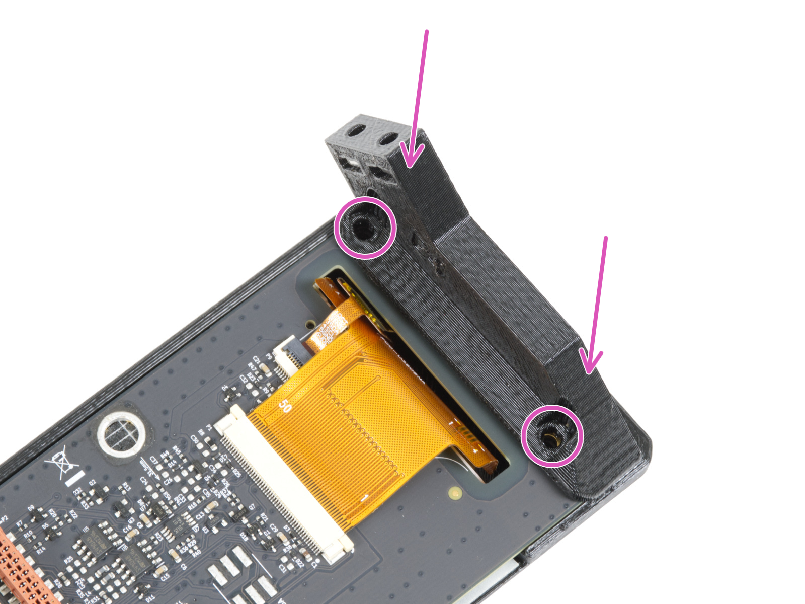
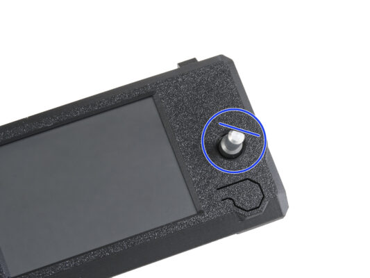
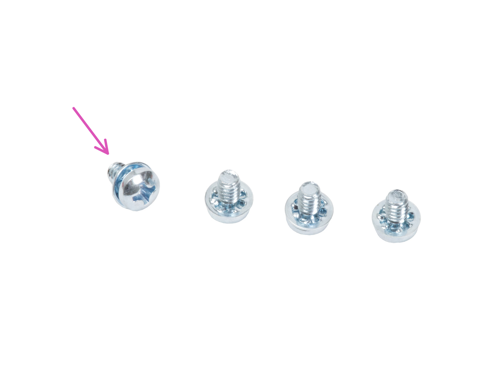
Attach the cover by using the two M3x10 screws through the marked openings. Note the openings are quite deep.


If you have a question about something that isn't covered here, check out our additional resources.
And if that doesn't do the trick, you can send an inquiry to [email protected] or through the button below.

