
内容
プリンターメンテナンス
- How to replace the CoreXY plastic parts
- How to install the Nextruder V6 Nozzle Adapter (XL single-tool)
- How to replace the Prusa Nozzle (XL single-tool)
- How to replace the Hotend assembly (XL single-tool)
- Packing printer for transport - Original Packing Material (XL)
- Prusaノズル(XLマルチツール)の交換方法
- How to replace a Z-axis motor (XL)
- Packing the XL Multi-tool for return - Original Packing material
- How to replace a heatbed tile and a heatbed tile cable (XL)
- How to replace a print fan (XL single tool)
- How to fix Modular bed error (HW solution)
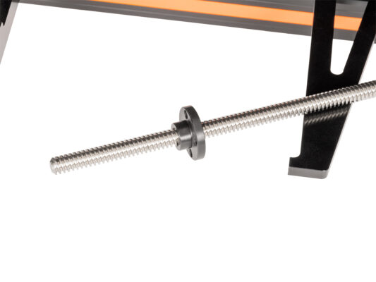
- How to replace trapezoid nuts (XL) [進行中の翻訳]
- 組み立てを始める
- Introduction
- Tools necessary for this chapter
- Unloading filament
- Printer preparing
- Spool holder removing
- Uninstalling the Wi-Fi antenna
- Detaching the filament sensor
- Cable cover removing
- Preparing the printer: placing the printer
- Uncovering the Z motor cable
- Releasing the Z motor
- CAUTION: Lubricant Handling
- Pulling out the Z motor
- Uinstalling the old trapezoid nut
- Installing the Trapezoid nut: parts preparation
- Installing the Trapezoid nut: installing the nut
- Installing the Trapezoid nut: Z motor attaching
- Securing Z motor: parts preparation
- Securing the Z motor
- Securing the Trapezoid nut
- Securing Bed-frame-mount-fixed
- Covering Z motor
- Turning the printer
- Cable cover attaching: parts preparation
- Cable cover attaching
- Preparing the Filament sensor
- Attaching the filament sensor
- Wi-Fiアンテナの取り付け:部品の準備
- Wi-Fiアンテナの取り付け
- Assembling the spool holder: parts preparation
- Assembling the spool holder
- Mounting the spool holder assembly
- XYZ calibration
- Good Job!
- How to clean the side filament sensor (XL)
- How to change xLCD and xLCD cable (XL single-tool)
- How to replace a Dwarf board (XL multi-tool)
- How to replace Nextruder heatsink (XL Multi-tool)
- How to replace a Dwarf board (XL single-tool)
- How to replace the Hotend assembly (XL multi-tool)
- How to replace a hotend thermistor (XL Single-Tool)
- How to replace a Z-axis linear rail (XL)
- How to replace a profile insert (XL)
- How to replace the hotend fan (XL Multi-tool)
- How to replace a PSU (XL)
- How to replace a hotend heater (XL Single-Tool)
- How to lubricate the coupler pins on Original Prusa XL (Multi-Tool)
- How to replace the tch-profile-insert (XL)
- How to replace the Sandwich Board (XL)
- How to replace the rubber band on Original Prusa XL (Multi-tool)
- How replace the CoreXY Cover Rear (Original Prusa XL)
- ネクストルーダーV6ノズルアダプターの取り付け方法 (XLマルチツール)
- How to replace a XY motor (XL)
- Packing the XL Enclosure for return - Original Packing material
- How to change the belt (XL)
- How to replace the main cable connector cover (XL)
- How to replace the PDU splitter (XL)
- How to replace the print fan (XL multi-tool)
- How to replace trapezoid nuts (XL)
- How to lubricate linear bearing rails (XL)
- How to change the xLCD (XL)
- How to set up a Buddy3D Cam
- How to replace Nextruder heatsink (XL Single-tool)
- How to replace a Nextruder (XL single-tool)
コメント
ログイン してコメントを投稿する
コメントなし