この章ではスプールホルダーを組み立てていきますが、その前に、スプールホルダーには2種類あることに注意してください。
⬢1. 現在の射出成形スプールホルダー
この古いバージョンは、最初のMK3Sバージョンまたは古いアップグレードユニットに付属していました。
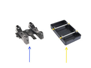
真空成型パーツの準備 に続きます。If the large portion of the box is occupied by the rectangular black trays, you have the first version, the older vacuum-formed spoolholders.