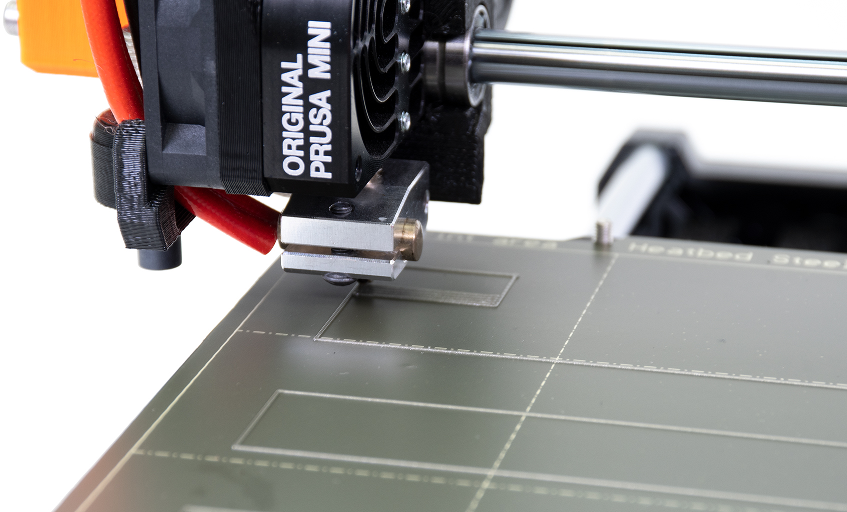
The First Layer Calibration is used to calibrate the distance between the tip of the nozzle and the print surface. The aim is to adjust the nozzle height until the extruded plastic sticks nicely to the bed and you can see that it is being slightly squished.
 | 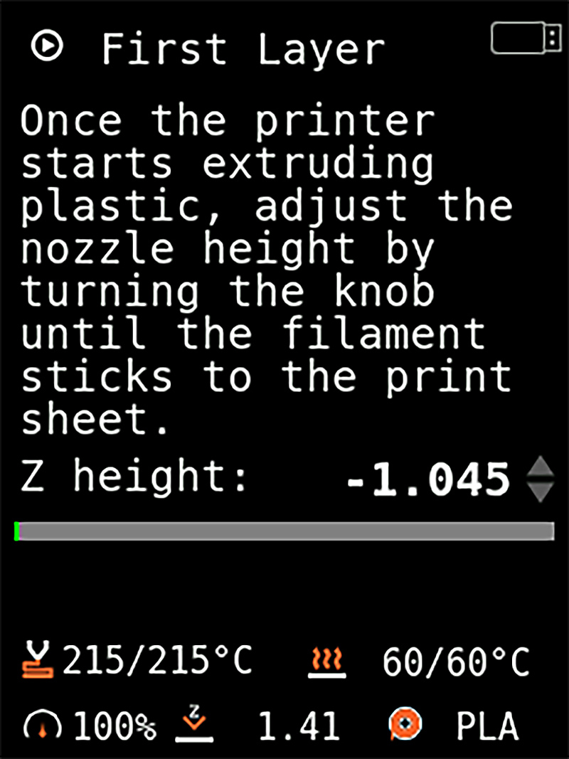 |
With a newly assembled or factory reset printer, the 'Z height' value will start at zero and move into a negative (-) value when you are reducing the distance between the nozzle and heat bed. The initial zero-value is set by the SuperPINDA/M.I.N.D.A. position. Turn the knob counter-clockwise to bring the nozzle closer to the bed and moving the value away from zero.
Calibration procedure
The first layer calibration is the last part of the initial calibration. It can also be run any time from LCD-menu -> Control -> Live Adjust Z.
Before proceeding, ensure the print surface (smooth or textured steel sheet) is clean. You can find information on how to clean it in PEI print surface preparation.
Smooth Sheet
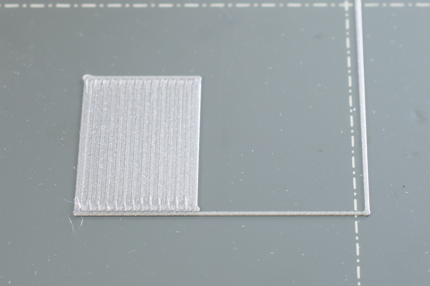
Too high
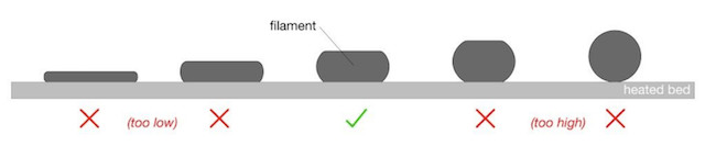
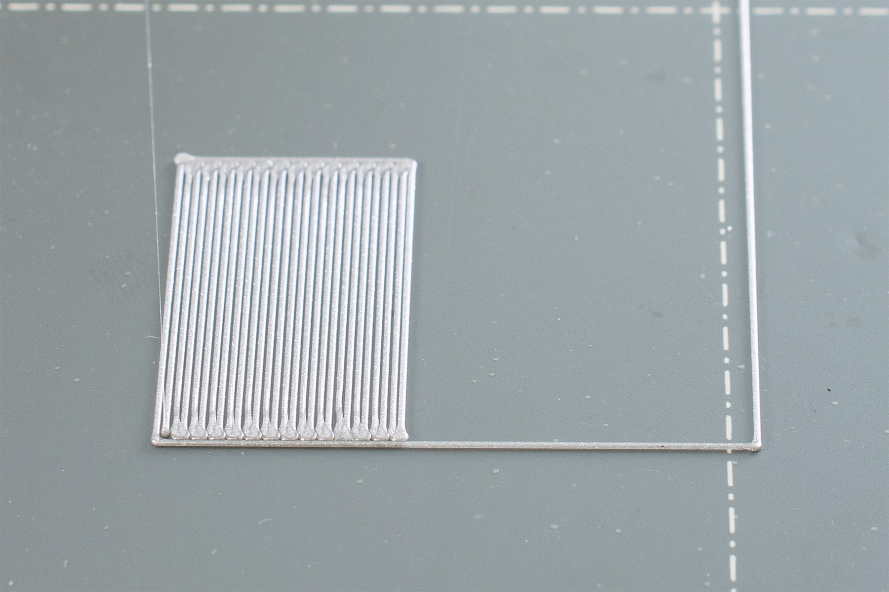
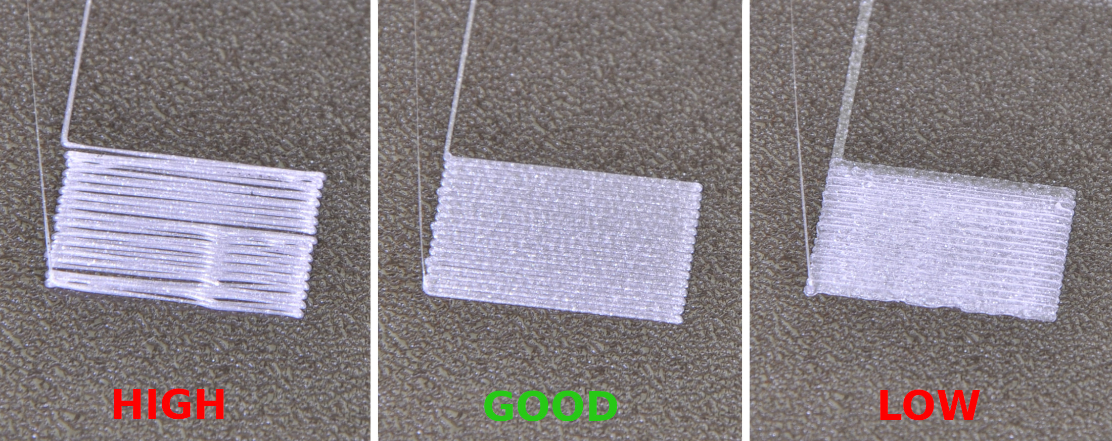
You want the line flattened, but not squished. On the square at the end of the test line, you do not want any gaps between the lines (left picture), which means it is too high. In that case, the value will be too close to zero. Prints will not adhere and can come loose during printing, which can, in turn, cause a blob.
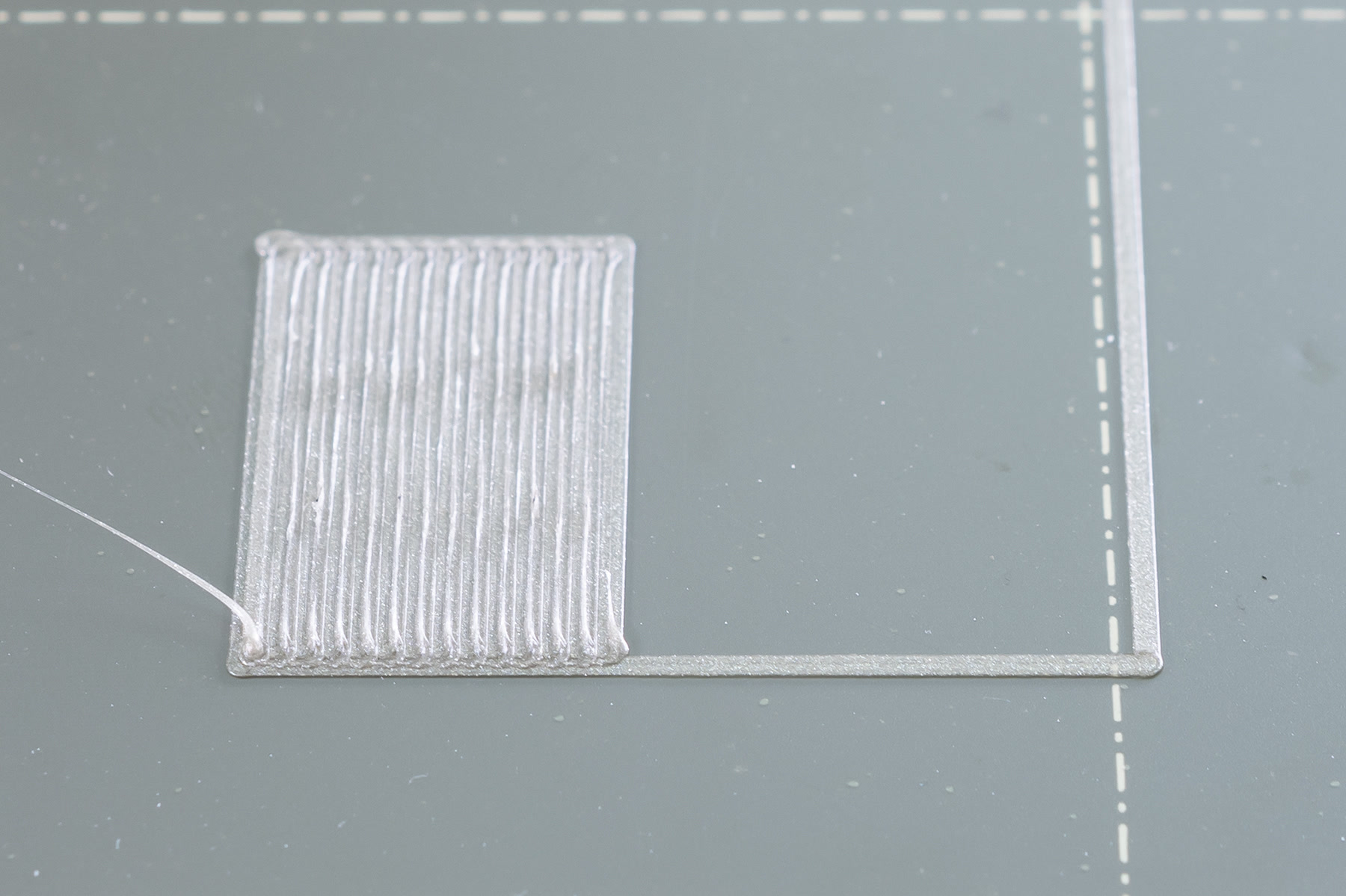
Too low
If the nozzle is set too low (right picture) you will see the line squished completely flat and the end square will have ridges between the lines. This is a clear sign of the nozzle being too close. The value will then be too far away from zero. When it is too low, the edges of the square can also start curling upwards. In the extreme, the filament will be spread so thin you will be able to see through the printed filament. This will clog your hotend.
Just right
A correct adjustment will show you an even surface (center picture), with no gaps, nor ridges, between the lines. As stated, the numeric value depends on the exact position of the SuperPINDA/M.I.N.D.A. sensor, which will be unique to each machine and means nothing without a visual reference. However, a common range is from -0.400 to -1.900.
 |  |  |
| Nozzle adjusted too high | Nozzle adjusted perfectly | Nozzle adjusted too close |
Textured sheet
The textured sheets are thinner than the sheets with smooth PEI, therefore you need to move the nozzle bit closer, but you are seeking the same results as with the smooth sheet. Again, if it is set too low (right picture) the filament can start curling up around the edges like it is not adhering. The numeric value will be too far from zero and must be adjusted back.
If set too high, you will see the line being round, and have gaps between the lines of the end-square. In this case, the value is too close to zero.
When to run the first layer calibration
Generally, the first layer calibration should be performed every time there is a major change in the assembly. This includes changing the nozzle, extruder upgrades, or other updates to any axis. You should also run all calibrations if you move the printer to a different location.
For First Layer Calibrations with other nozzle diameters than 0.4 mm, please see this article.
Steel sheet profiles
Since the thickness of the different flexible steel sheets varies with the type, you will require a separate Live Z adjustment for each sheet. Therefore the printer offers 'Steel sheet profiles', where you can set a first layer calibration for each sheet you may have. More info in Steel sheet profiles.
10 comments
So I put 5 rectangles 0.2 mm high (one layer) with size 20x20 at the corners and in the center and calibrate that way. Is this correct at all?
Calibration cube also looks way better. Also I find that dial-up "Extrusion multiplier" also play a crucial role for me. Original settings are way too low.
I'm using Prusament PETG and SATIN sheet.