Unlike FDM supports, which are usually lattice or grid-like, SLA supports are scaffolding tree-like structures with thin tips. When removed, they’re easy to remove and leave little to no traces on the printed object’s surface. This also means that an insufficient number of supports can lead to unwanted effects – e.g., heavy objects can detach during the print.
Starting from PrusaSlicer version 2.9.1, the automatic supports are generated based on the size and type of supported part:
- Small islands are supported by a single point placed at their center of mass.
- Medium islands use the Voronoi diagram to optimally place two or more supports.
- Large islands are divided into thin and thick sections, where supports are placed either along the central axis or around the perimeter for greater stability.
- For detected overhangs, PrusaSlicer adjusts the support density based on Z height and overhang angle, minimizing unnecessary supports and ensuring even distribution.
The supports are identified by colour, distinguishing islands in blue, manual edits in orange, and overhang supports in white.
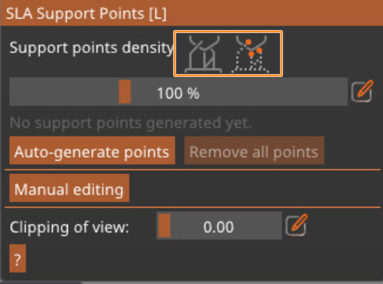
To generate the supports, select the model, click on the SLA support points icon, and click on Auto-Generate points. The two top icons will allow you to switch the view between showing the tree supports and only showing the support points. The sliding bar will adjust the support points density, which will automatically show in the preview when changed. The standard value should be good for most cases.
Also, remember that removing the supports can leave tiny marks on the surface, so if your object has areas that should be completely flawless (an ornament on a piece of jewelry, the face of an action figure), try to keep the supports away from them.
Manual support editing
If you wish to edit the supports, click on the Manual editing button. This will allow you to add new points by clicking the left mouse button and remove points, including automatically generated ones, by clicking the right mouse button. Selecting a point and dragging it will move the point.
If you have manually added points, the automatic support generator will consider them and adjust the surrounding support density accordingly.
The option "Lock supports under new islands" will lock the blue points, making only the overhangs and added points possible to be edited.
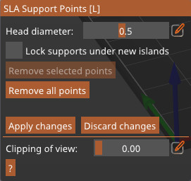
You can tweak the support thickness in manual editing mode by using the Head diameter slider, or you can go to Print settings -> Supports and modify the following parameters to increase the thickness of supports:
- Support head front diameter: 0.6 mm
- Support head penetration: 0.6 mm
- Support pillar diameter: 1.3 mm
 | 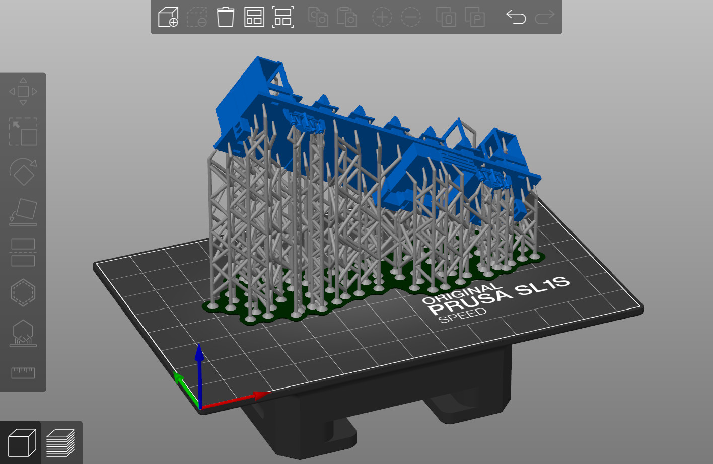 |
Comparison of automatically generated supports and manually edited supports
Useful shortcuts
Left click Add point
Right click Remove point
Drag Move point
Shift + left click Add point to the selection
Alt + left click Remove point from selection
Shift + Drag Select by rectangle
ALT + Drag Deselect by rectangle
CTRL + A Select all points
Delete Remove selected points
CTRL + Mouse wheel Move clipping plane
R Reset clipping plane
Enter Apply changes
Esc Discard changes
M Switch to editing mode
A Auto generate points
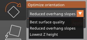
Orientation
Supports go hand in hand with object orientation – by rotating the object to an optimal position, you can minimize the need for supports. You can also go to the left side menu and click on the rotate tool. This will show you the option to turn the object to the angle with the least amount of overhangs.
5 comments
Probably not. Does not make sense for Print speeds etc with FFF printing. Just looks cool.
The very same object (a simple post cap) sliced in latest CURA 4.13.1 with tree support takes 7h52m and 125g of filament, while the latest PrusaSlicer 2.4.1 requires 11h16m and 200.5g of filament with its "standard" supports.
Same (default) settings, same printer (MK3), original Prusa printer profiles. Sure there may be differences in detail (e.g. the PrusaSlicer uses 4 top layers as default, where Cura with original Prusa profile uses only 3), but those only make a difference of a few minutes and a gram or two in filament consumption and don't change the overall picture.
Supports are not the forte of PrusaSlicer (never have been) and you should better acknowledge that and try to improve, rather than dismissing this topic.
The support head diameter (when manually editing tree supports) can vary. When you click on the model, the current head diameter is used, so you can have tiny connection to the model, thick and extra thick one all at once. However the rest of the support settings can only be changed either globally or for individual objects. You cannot have different support base diameter on the same model at the moment.
I think we will eventually, but there are other considerations with FFF than SLA printing. Even more so when you want to use the MMU2S. We always try to cover most edge-cases as well as general use before releasing a new feature. You can also use another program, like Meshmixer, to generate the tree supports.
Does it involve meshmixer ?