Layer height
Height of the individual slices/thickness of each layer. Layer height is the main factor affecting both:
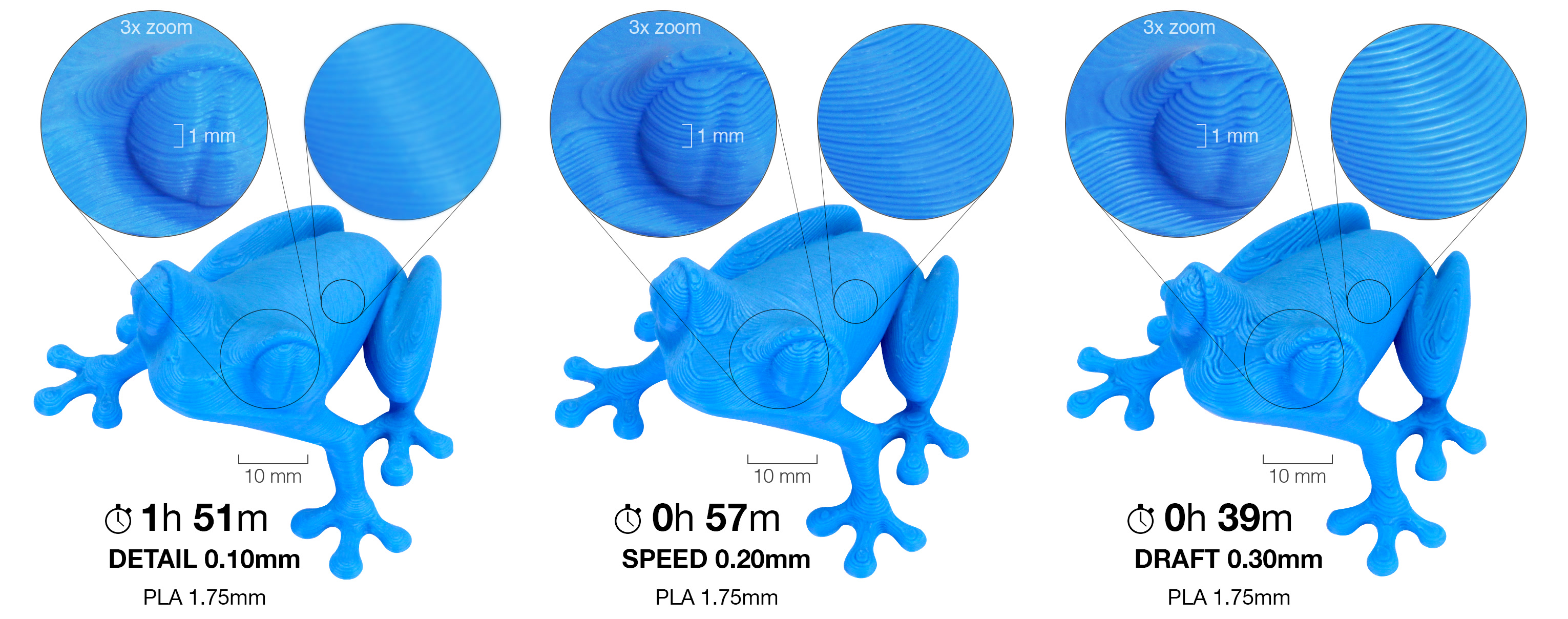
- print time
- vertical resolution
By choosing taller layer heights you can significantly shorten the print time at the cost of more visible layers. On the other hand, choosing a small layer height (e.g. 0.10 mm) will result in extra detail at the cost of longer print times.
Generally, we do not suggest going lower than 0.10 mm as the improvement in print quality with 0.07 or 0.05 mm layers is relatively minor with significantly longer print times.
Keep in mind, that layer height changes only the vertical resolution. For example, an embossed text parallel with the print bed will look the same regardless of the layer height. If you’re looking for increased resolution in the XY plane, check nozzles with a different diameter.
The layer height should be below 80% of the nozzle diameter (e.g. the maximum layer height with a 0.4 mm nozzle is about 0.32 mm). The layer height cannot be higher than the nozzle diameter, PrusaSlicer will display an error message if you try to input such a value.
You can also consider using the Variable layer height function.
First layer height
When printing with low layer heights you might still want to print a thicker first layer to increase adhesion to the print bed. Original Prusa print profiles always use 0.20 mm as the first layer height.
You can express this as an absolute value (e.g. 0.20 mm) or a percentage of the default layer height (e.g. 150%).
Changing the first layer height will most likely require adjusting the calibration of the first layer on your printer.
Perimeters
Defines the minimum number of outlines that form the wall of a model. Original Prusa profiles always use a minimum of two perimeters.
The strength of a model is mostly defined by the number of perimeters (not the infill). If you want a stronger print, increase the number of perimeters.
Spiral vase
Creates a continuous single outline container, gradually increasing the Z height.
When printing anything with a single-perimeter wall, there is always a small flaw where the printer advances to the next layer. This spot, where the printer stops and finishes the perimeter, raises the Z height by the layer height and starts a new perimeter, creates an unsightly ‘scar’ running up the side of the model. This scar is also a weak point of the print.
the spiral vase does not have any such point where the layer changes, except the first N bottom solid layers. Instead, the height is increasing gradually all the time, until the top of the print is reached.
When the vase mode is activated, PrusaSlicer automatically sets related settings accordingly:
- one perimeter
- 0% infill
- disabled top solid layers
- disabled supports
- disabled "ensure vertical shell thickness"
You can still adjust the number of bottom solid layers. Furthermore, you can adjust the External perimeters Extrusion width in the Advanced menu to get a thicker/stronger/watertight vase (e.g. from 0.45 to 0.6).
The model should be defined as a solid. Otherwise, PrusaSlicer will try (and fail) to create both inside and outside surfaces, so model the outside dimensions only.
Only one object at a time can be printed in the vase mode. If you had multiple objects on the print bed, it would be impossible to print them continuously. You can get around this limitation by enabling Sequential printing.
Recommended thin wall thickness
For a selected number of perimeters and layer height, PrusaSlicer calculates the optimal thin wall thickness. If you go back to your CAD drawing and change the wall thickness to this exact value, you will eliminate unnecessary perimeter overlap and your print will have a perfect wall surface finish.
Normally you get recommendations for an even number of perimeters (2,4,6…). If you enable Detect thin walls, you will also get a recommendation for an odd number of perimeters (1,3…).
You may think, that when the extrusion width for a perimeter is 0.45 mm, two perimeters will be 0.90 mm wide (2x0,45). However, if you look at the recommendation for a 0.2 mm layer height, you will find that this is not true and the suggested value is 0.86 mm.
In order to understand how this number is calculated, we need to take a look at the perimeter cross-section. PrusaSlicer assumes that the cross-section of an extrusion is a rectangle with semicircular ends. Note that the extrusion width includes the two semicircular ends.
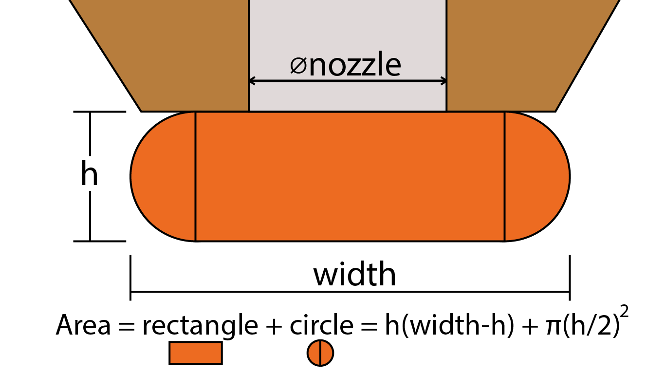
(This image is a re-draw of the original source: https://manual.slic3r.org/advanced/flow-math)
Now let’s add a second extrusion/perimeter. If we suppose no overlap (tangent paths), there would be empty space (yellow). In order to fill the empty space and bond the perimeters together, PrusaSlicer slightly overlaps the perimeters. This is essentially why you can’t just multiply the number of perimeters by the width of a single perimeter to get the ideal wall thickness.
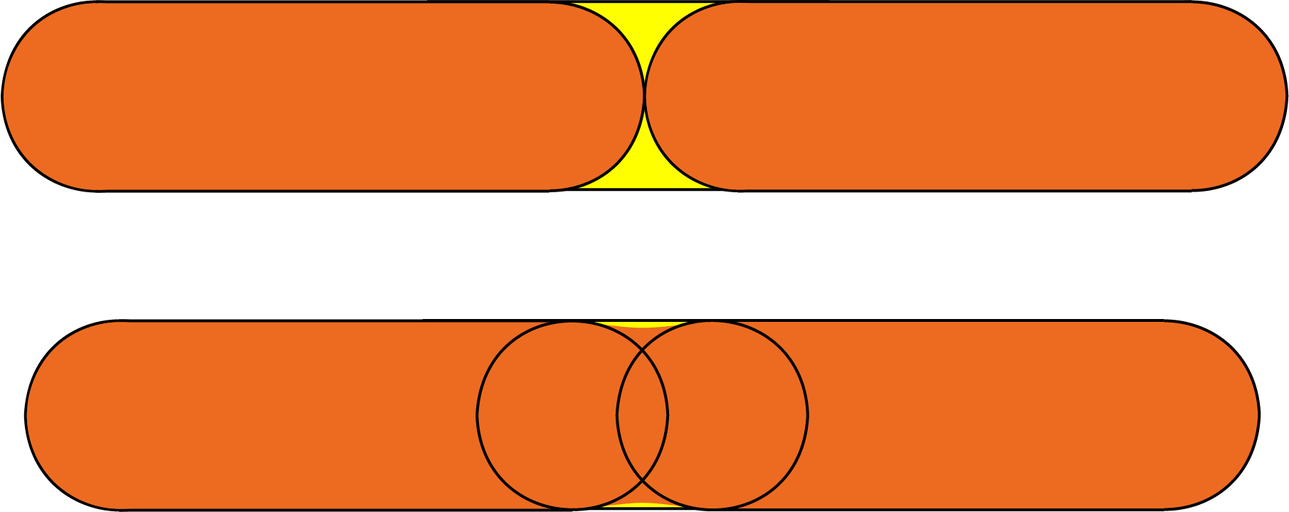
(This image was heavily inspired by the original source: https://manual.slic3r.org/advanced/flow-math)
For more information, check the Slic3r Flow math page (parts of this text are sourced from the same page).
Solid layers - top/bottom
The bottom and top parts of models are usually filled with solid layers (100% infill).
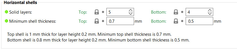
You can set how many top and bottom layers you wish to print. You can also set a minimum wall thickness, which is especially useful when using the variable layer height function. The tooltip below these settings will update with every change, giving you a better idea of the resulting top/bottom wall thickness.
Setting the top or bottom solid layers to 0 overrides the minimum wall thickness. So you don't have to set the minimum wall thickness to 0 as well to get top or bottom layers.
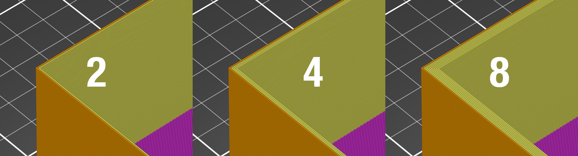
The top solid infill is essentially bridging over the infill pattern. Because of that, you’ll almost always see some sag in the first few solid infill lines. The lower the infill, the longer the bridging distance, and as a result the bigger the sag. This can be counteracted by simply increasing the number of solid layers - we suggest at least 3 top layers. You can further reduce this behavior with a modifier mesh, which increases the infill for the last few layers before the solid infill.
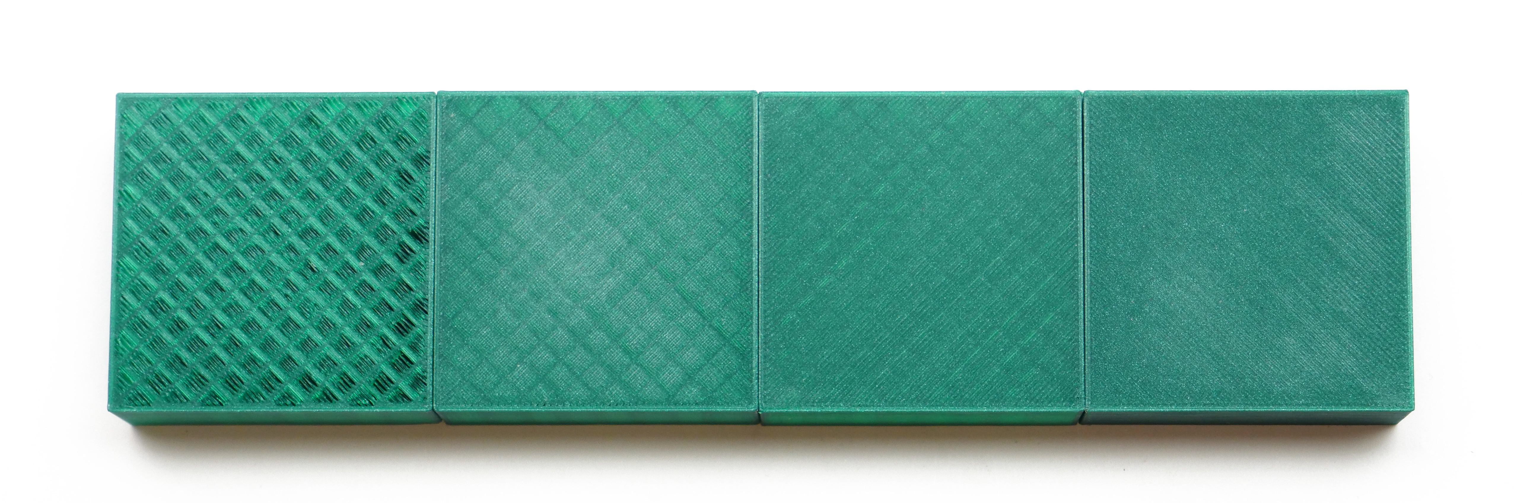
From left to right, 1, 2, 3, and 5 top layers, printed at 0.1 mm layer height.
Note that when printing at low layer heights, you will need more solid layers to achieve the same top/bottom wall thickness (e.g. with 0.3 mm layer height use 3 top layers, with 0.1 mm layer height use 9 top layers).
The default solid infill pattern is rectilinear, however, there are several other patterns to choose from.
Extra perimeters if needed
A legacy option that as far as we know, doesn't do anything anymore. Let us know if you find a case where this changes anything.
Ensure vertical shell thickness
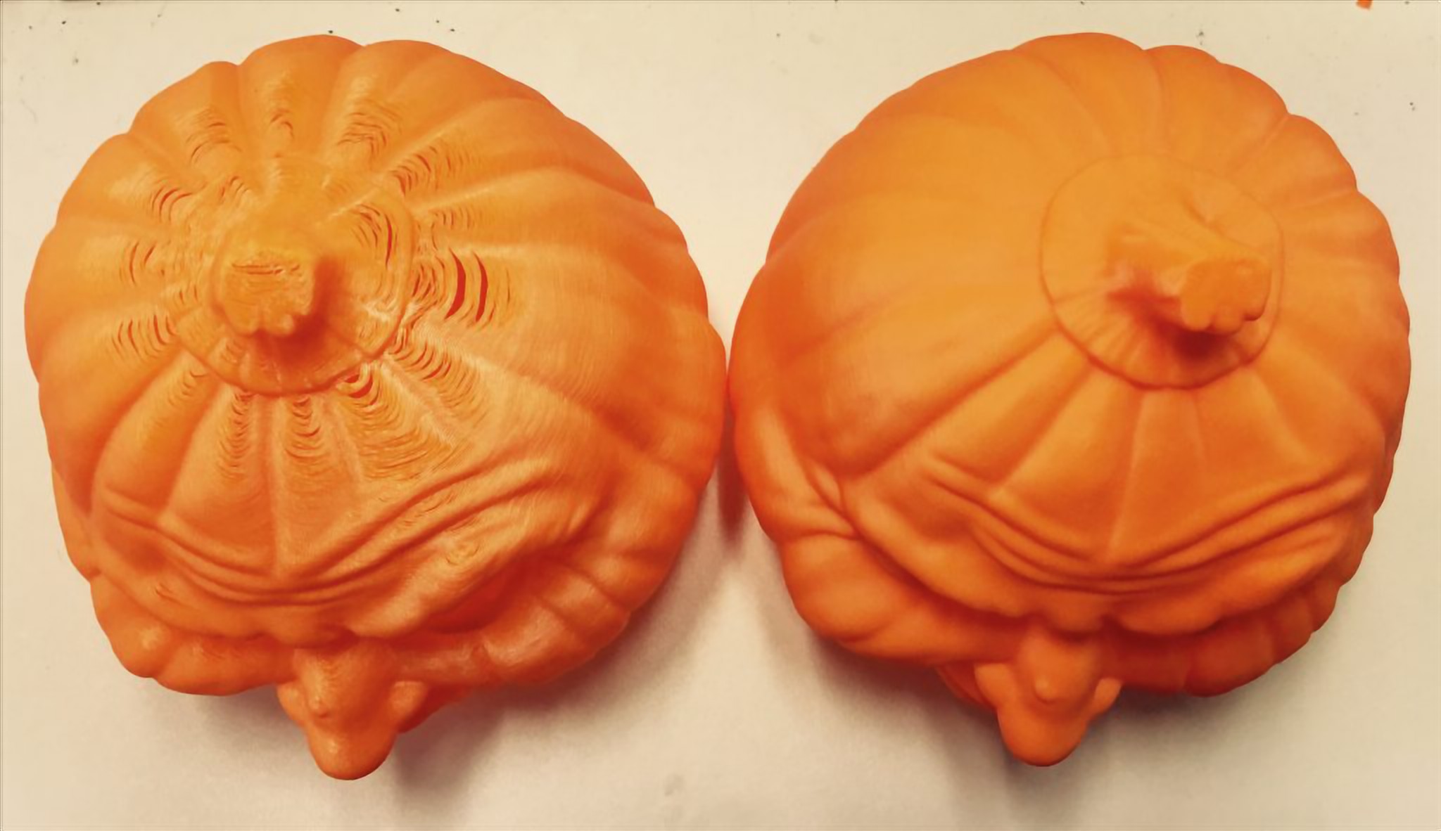
This function solves one of the biggest issues of older slicers, holes between the perimeters on a slanted surface. This was typical when printing busts and other organic-looking models. Such objects typically had a few holes on top of the head. With this function enabled, PrusaSlicer ensures it lays down the needed (internal) supports for perimeters in an upcoming layer.
- Disabled: Produces additional extrusion only to support top layers. Choosing this option may cause your print to fail.
- Partial: Provides partial support to vertical shells without fully enforcing the required thickness.
- Enabled: Standard setting. Enables the addition of solid infill near sloping surfaces to guarantee the vertical shell thickness. It is applied to the top and bottom solid layers.
Avoid crossing perimeters
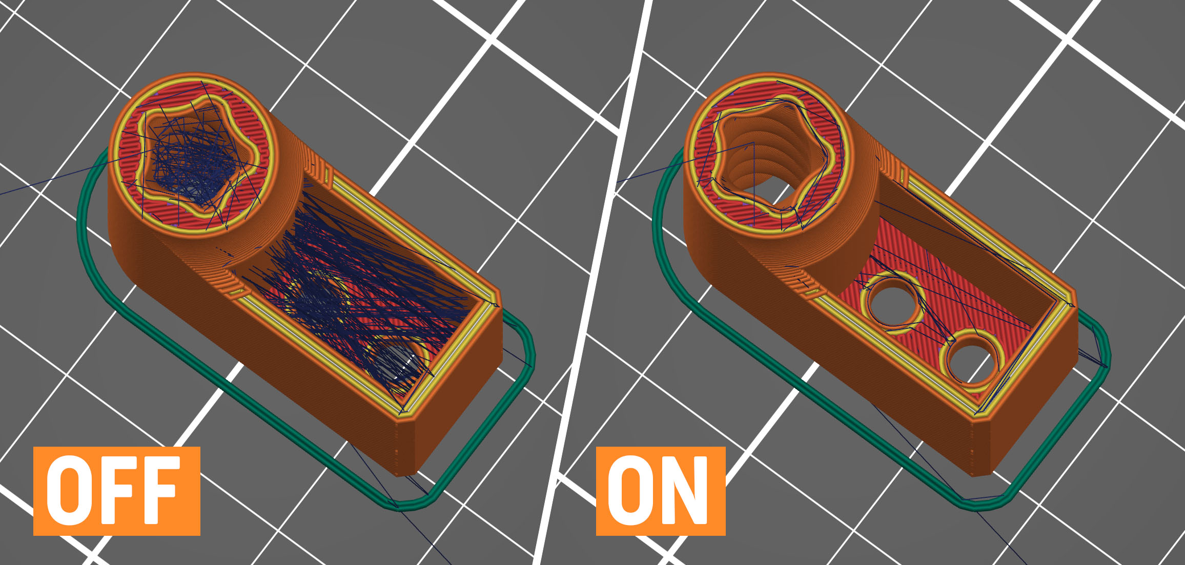
Avoid crossing perimeters is an algorithm to minimize crossings of external perimeters during travel moves, which reduces stringing (especially with Bowden extruders) and improves overall print quality.
Enabling this feature slows down the G-code generation and increases print time somewhat (time increase varies between models).
This feature was significantly improved in PrusaSlicer 2.3. The new algorithm tries to route a travel path inside object islands with the shortest path while avoiding holes and concavities, while it takes the shortest path when traveling between islands.
If the detour is longer than the Max detour length, avoid crossing perimeters will not be applied for this travel move. You can use absolute values in millimeters, a percentage of the travel move, or set it to 0 to disable Max detour length check.
Detect thin walls
By default, every wall consists of outside and inside perimeters (a minimum of two perimeters for thin walls). If there is enough space, an infill pattern fills the void between these inside/outside perimeters.
Enabling Detect thin walls lets PrusaSlicer generate a single perimeter that works as both an inside & outside shell. This will help to capture tiny details. However, walls thinner than a single perimeter extrusion width will likely still be ignored.
This feature is automatically disabled if the Arachne perimeter generator is active, as it already automatically adjusts for thin walls.
Thick bridges
For historical reasons, PrusaSlicer used to print bridges with extremely thick lines. This makes bridging very reliable and lets you bridge longer distances, but they didn’t look good. The new default behavior uses your current layer height for bridging, making bridging reliable for shorter distances but looking significantly better. This is the strategy that most modern slicers use. You can switch to the old behavior by enabling the Thick Bridges option. Since the first solid layer above supports uses the bridging settings, this change also has a big impact on how supported overhangs look.
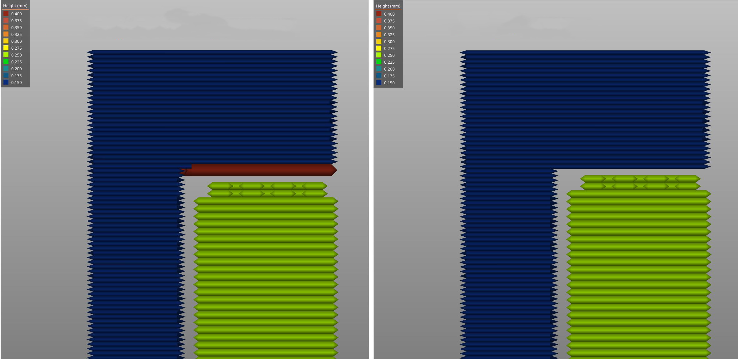
Left: Thick bridges enabled, Right: Thick bridges disabled
Detect bridging perimeters
Enables bridging flow for overhangs and turns on the fan.
External perimeters first
Perimeters will be printed from the outermost to the innermost ones instead of in the inverse order.
This parameter may help with dimensional accuracy since the outer perimeter is laid down first and any extra filament extruded when printing following perimeters is pressed back away from the outer wall. On the other hand, the surface may be slightly less smooth.
Fill gaps
Enables filling of gaps between individual perimeters and between the innermost perimeter and infill.
Perimeter generator
This setting lets you switch between the Arachne (default) and the Classic perimeter generator. The Arachne perimeter generator automatically adjusts the extrusion width of perimeters as needed. For most prints, the Arachne perimeter generator is superior, but for some functional prints where the accuracy of concave corners is important, the classic perimeter generator may be better.
Only one perimeter
This option forces a single perimeter on top or first layers to achieve a cleaner, more uniform aesthetic finish without sacrificing the object's structural rigidity. The top and bottom layers can be controlled separately in Print Settings -> Layers and perimeters -> Only one perimeter.
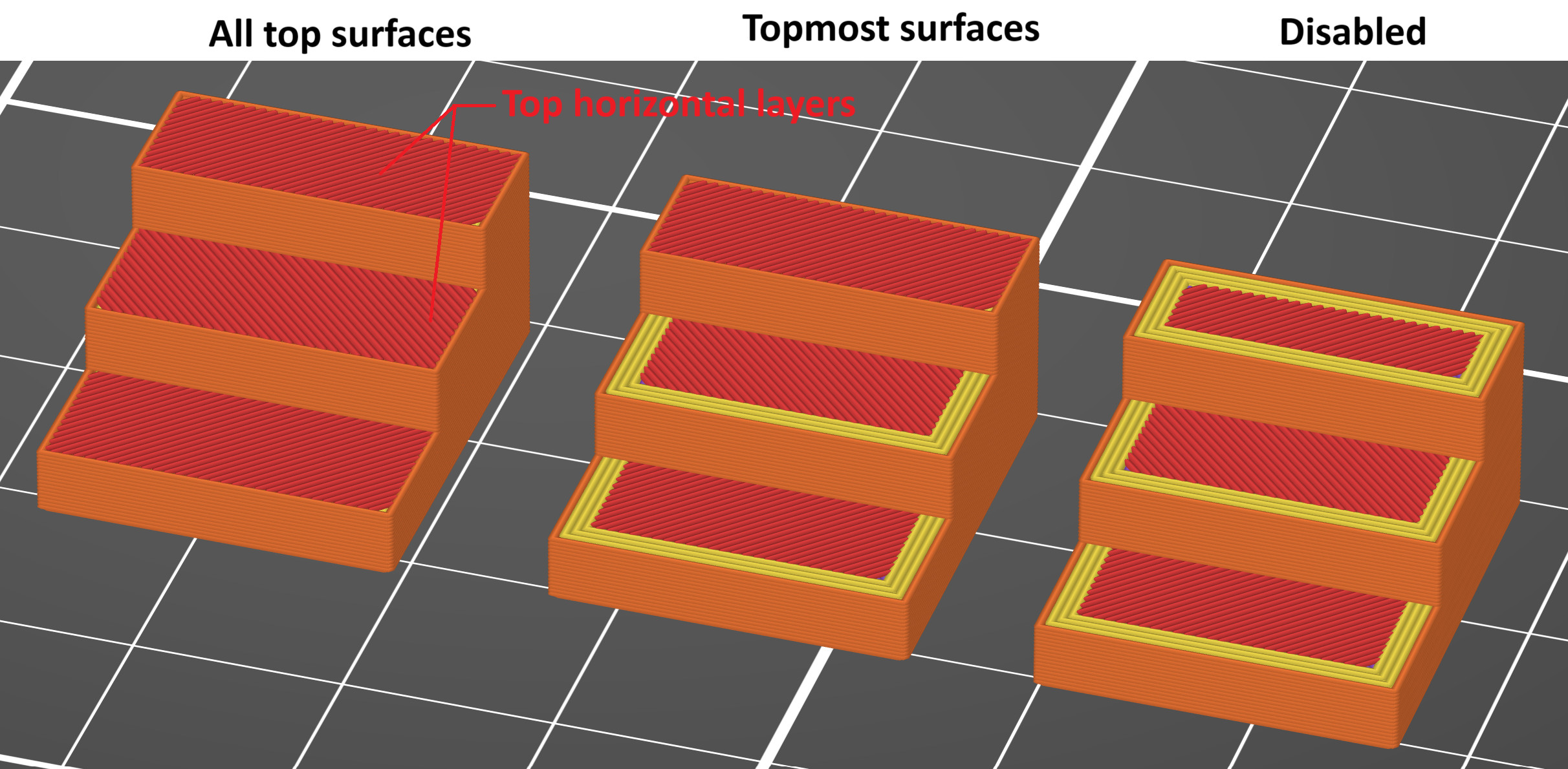
Single perimeter on top surfaces
- Disabled Standard: perimeter settings are applied to the top layers.
- All top surfaces: A single perimeter is applied to all horizontal top layers.
- Topmost surface only: A single perimeter is selectively applied only to the final visible top model surface.
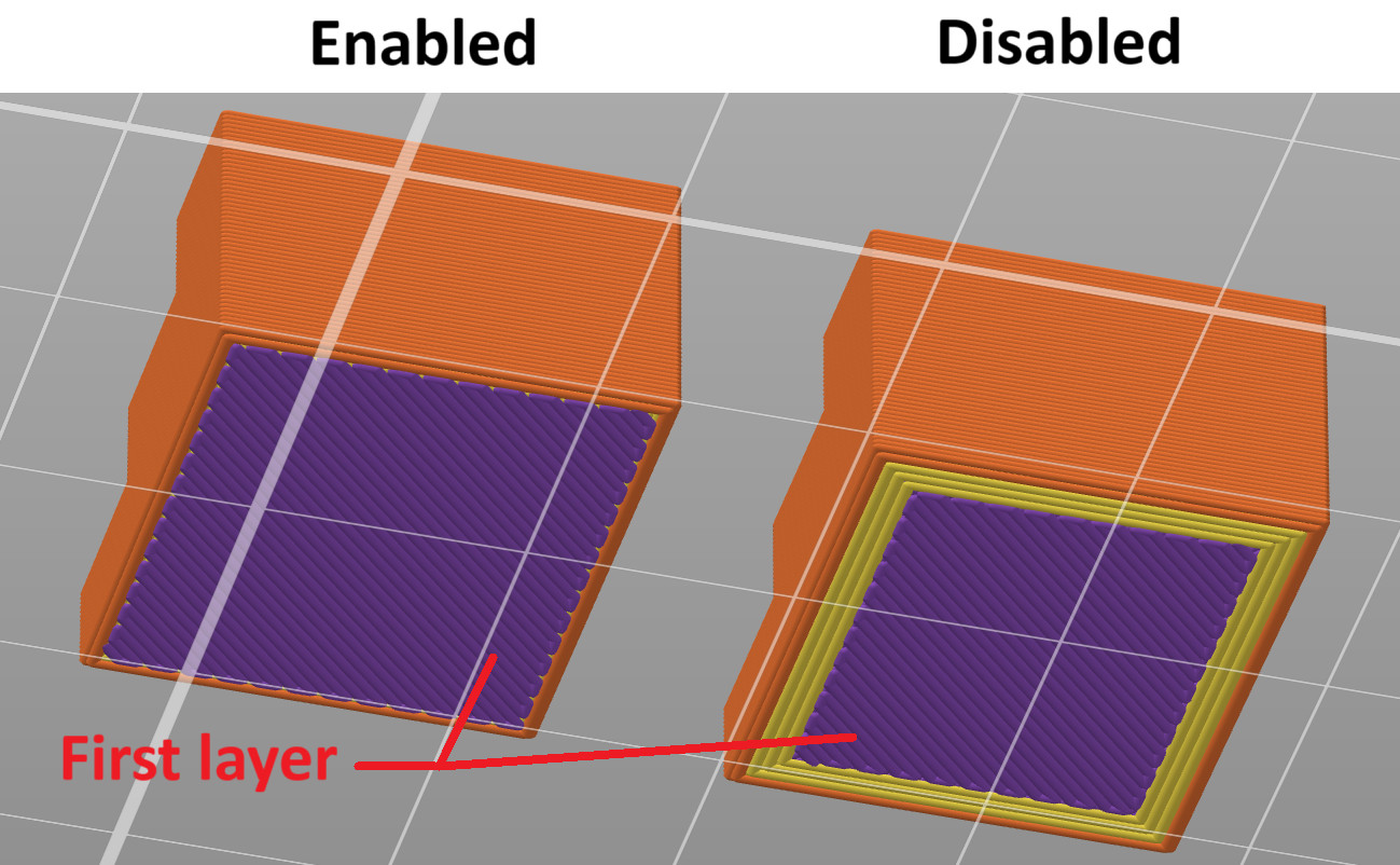
Only one perimeter on the first layer
This setting can be either enabled or disabled to force a single perimeter specifically on the first layer.
38 comments
.15 Speed.20 Structural.20 Speed.20 Breakaway Full.20 Breakaway Interface.20 Soluble Fill.20 Soluble Interface.
Where do I find information on when to use these? Link.
I started with .20 Speed but had a problem once so changed to .20 Structural. Does the .20 Speed require a full flow nozzle or does it work with any nozzle?