Printing with different nozzle diameters is an experimental workflow as it requires tweaking several settings in profiles, and some nozzle combinations may be incompatible, potentially causing unsuccessful prints. However, we would like to open this option to experienced users and developers. We look forward to collecting your feedback to improve this feature and continue its development.
Due to it being a difficult process, this article will explain how to print with different nozzle diameters in a step-by-step example. We used:
- Printer: XL 5T – use of 2 tools
- Used nozzles: Tool 1: 0.25 mm, Tool 2: 0.6 mm
- Usage: Nozzle 0.25 mm for perimeters and support structure, Nozzle 0.6 mm for object infill
- Supports: Organic Supports

Before Starting
Change the nozzles on your XL by following the manual How to replace the Prusa Nozzle (XL multi-tool). To achieve a successful print, it is recommended to do a Tool Offset Calibration, which can be found in the printer menu in Control -> Calibrations & Tests.
Handling of Profiles
Select the Correct Profile
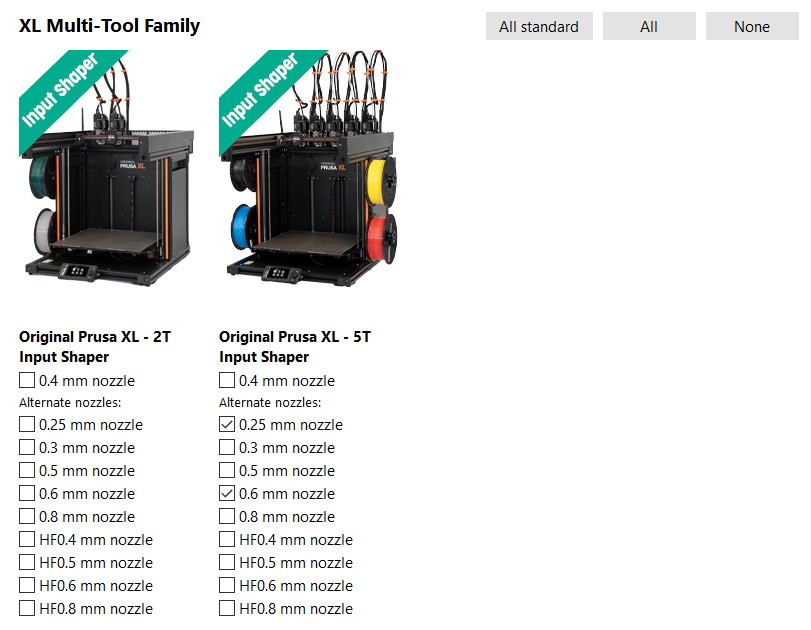
To switch between available profiles, go to the Wizard (Configuration -> Configuration Wizard -> Prusa Research) and select the printers with the nozzles you want to use. See the example below where the 0.25 mm and 0.6 mm nozzles that are used are selected.
Print Settings Changes
Combining infill
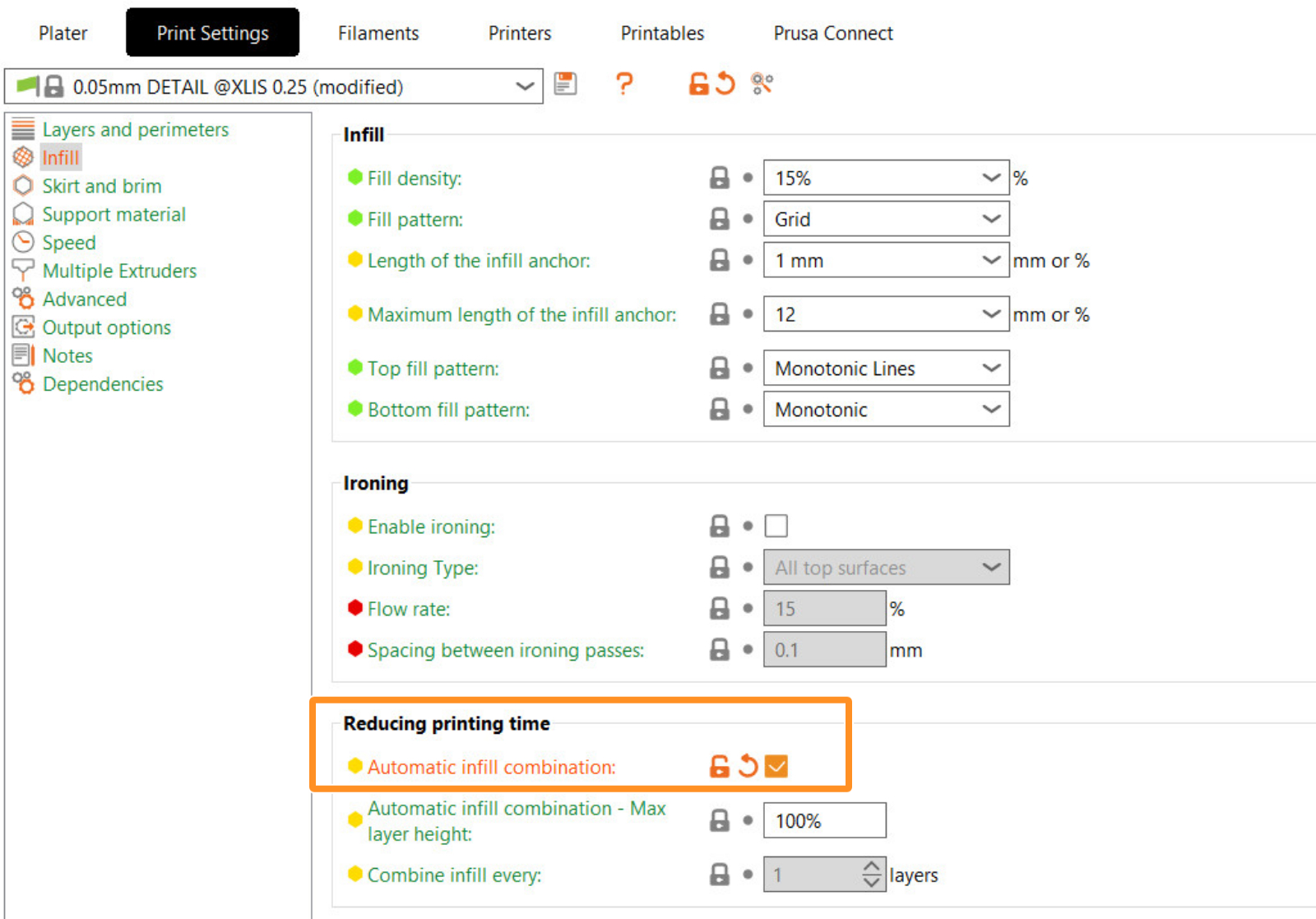
For some use cases, when printing with different nozzle diameters it may be useful to print infill every nth layer, typically when the infill is printed with a larger nozzle. To cover these scenarios, you can set it up manually (infill_every_layers) or switch to automatic infill combining (Print Settings -> Infill -> Automatic infill combination).
Enable supports
Enable the supports in Print settings -> Support material -> Generate support material. In Style, choose Organic.
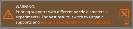
When printing with different nozzles, compatibility of supports with the wipe tower and the option to select the support material extruder is critical. Therefore, we highly recommend using Organic Supports. Organic Supports synchronize layers with the object, making things much simpler. This allows you to choose the support material extruder and at the same time have the wipe tower active.
Assigning Extruders
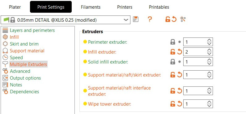
To assign extruders to specific features of the printed model across the project, go to Print Settings -> Multiple Extruders -> Extruders, and assign the extruder numbers based on your use case. For our example, we are using:
- The Perimeter extruder is set to Extruder 1 to achieve a detailed surface of the model.
- The Infill extruder is set to Extruder 2 because I want the infill to be rough.
- The Support material/raft/skirt extruder is set to Extruder 1.
- The Support material/raft/interface extruder is set to Extruder 1.
- The Wipe Tower extruder is set to Extruder 1.
This setup ensures that the supports are printed with a single extruder. Specifically for supports, a single extrusion width for the entire structure is selected and its width is based on minimal nozzle diameter. If you leave the extrusion width at zero all extruders could print on supports and you may experience under-extrusion with larger nozzles.
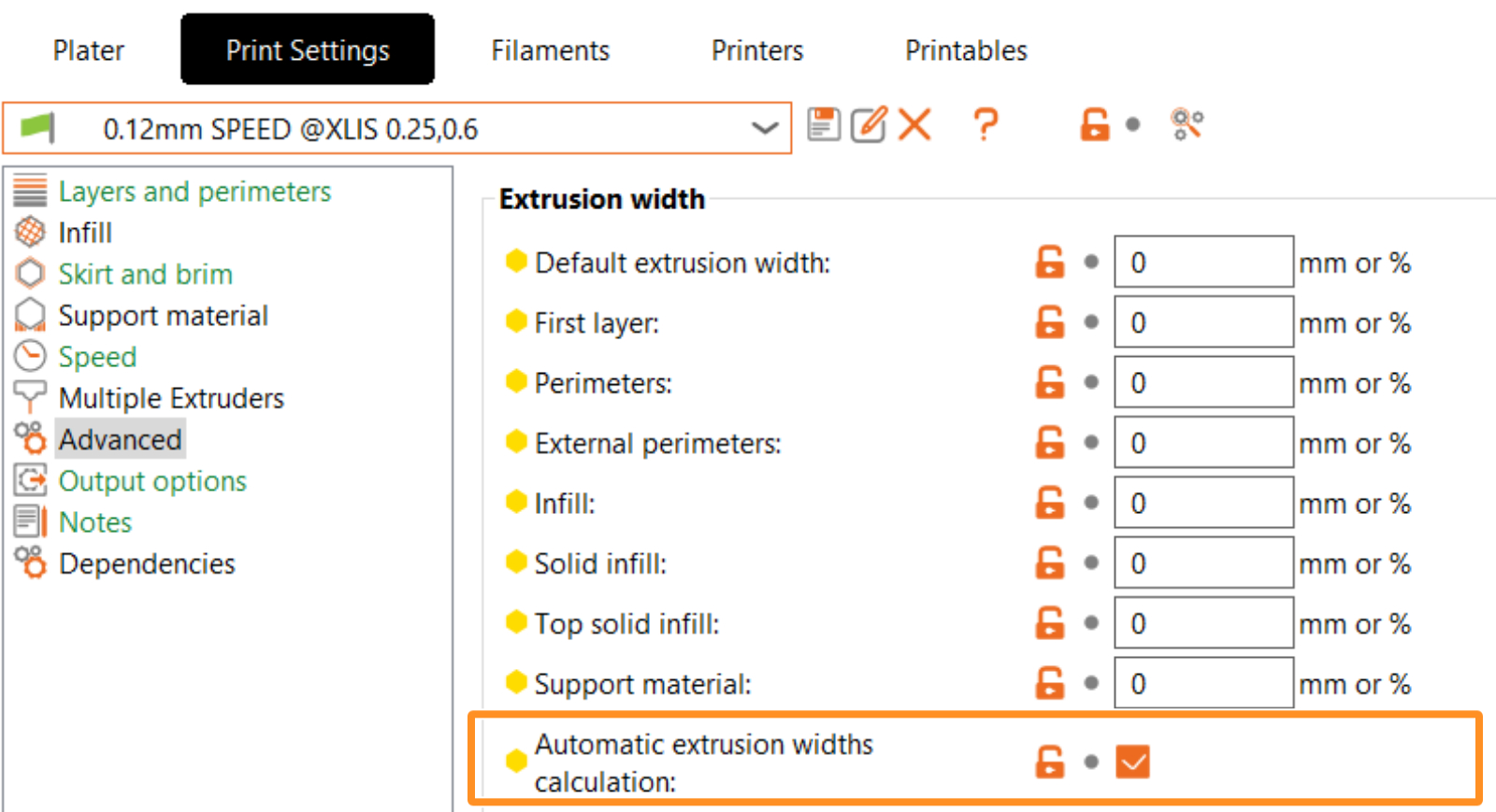
Extrusion Widths
To achieve the correct extrusion width when using different nozzle diameters for specific features of the model, we provide automatic extrusion width calculations (Print Settings -> Advanced -> Automatic extrusion widths calculation). When this option is enabled, a window will pop up warning that the extrusion widths will automatically be set to zero, and the system will calculate them based on the currently used nozzle diameters.
Managing Compatible Printers Condition
This step is optional, but it is possible to edit the print conditions of the default profile for a more flexible handling of the print profile. This lets you share settings with all XL printers (printer profiles). For that, go to Print Settings - Dependencies -> Compatible Printers condition. We have changed it from "printer_notes=~/.*XLIS.*/ and nozzle_diameter[0]==0.25" to "printer_notes=~/.*XLIS.*/"
Note that profiles for different nozzle diameters may have varying parameters. If you want to use this profile for another purpose, be sure to check for any differences in parameters between your custom-derived profile and the default one. For instance, parameters such as speed and acceleration may be critical, but other settings could also vary.
After that, you can save the Print Setting profile. It will show as a user preset.
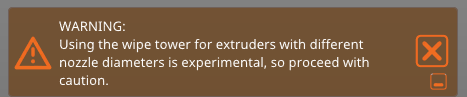
Note to the Wipe Tower
Based on basic tests, the wipe tower can handle printing with different nozzle diameters, but we cannot guarantee a successful print with all possible combinations of settings. That’s why the warning remains active.
Printer Settings Changes
To configure your custom nozzle diameter hardware setup go to Printers tab - Extruder #. In corresponding extruders set up nozzle diameter. We also highly recommend changing the minimum and maximum layer height limits for the corresponding extruders. This will limit the range of compatible print profiles based on the minimum and maximum layer height values. We have left the Extruder 1 with the selected 0.25 mm nozzle and changed the Extruder 2 to 0.6 mm.
 |  |
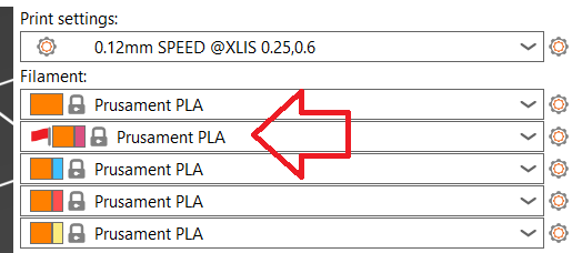
Incompatible Filament Profiles
When changes are made to the printer profiles, especially due to a nozzle change, incompatible filament profiles will appear with a red flag. It is important to select profiles without red flags to ensure proper functionality.
10 comments
Maybe this could be added as a new Filament Overrides section for Extrusion Widths?
Managing Compatible Printers Condition
This step is optional, but it is possible to edit the print conditions of the default profile for a more flexible handling of the print profile. This lets you share settings with all XL printers (printer profiles). For that, go to Print Settings - Dependencies -> Compatible Printers condition. We have changed it from "printer_notes=~/.*XLIS.*/ and nozzle_diameter[0]==0.25" to "printer_notes=~/.*XLIS.*/"
Hope this helps :)
I can't find it documented, but IIR the slicer always layed down extruder #1 before #2 (assuming both were in use within that layer). Ie if you has text, slightly better results could be achieved by ensuring text color was on extruder #1.
With small alongside large nozzles, this would become even more important.
Please confirm what the system intends (and ideally is it documented publicaly?)