日本語
Login
3Dプリンター
マテリアル
部品 & アクセサリー
ソフトウェア
3Dモデル
応用事例
コミュニティ
ヘルプ
アカデミー
ブログ
会社概要
サポート
Original Prusa MINI+
MINI+ kit assembly (draft) [進行中の翻訳] (v1.1)
5. LCD assembly & Electronics | Tools necessary for this chapter
1. Tools necessary for this chapter
Step 1 of 26 (Chapter 5 of 9)
内容
コメント
⬢
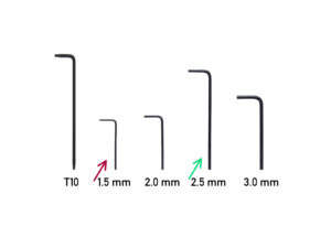
この章で、準備するもの:
⬢
1.5mm Allen key
⬢
2.5 mm 六角レンチ
Loading...
次
内容
MINI+ kit assembly (draft) [進行中の翻訳] (v1.1)
1. Introduction
2. YZ - axis assembly
3. X-axis & Extruder assembly
4. Print head & Heatbed assembly
5. LCD assembly & Electronics [進行中の翻訳]
Tools necessary for this chapter
LCD assembly: parts preparation
Mounting the LCD
Connecting the LCD
LCD cable guidance
LCD assembly: reward yourself!
Optional: ESP Wi-Fi Module
Power switch: parts preparation
Mounting the power switch
電源スイッチの接続
Filament sensor: parts preparation (optional)
Filament sensor: parts preparation (optional)
Filament sensor assembling (optional)
Filament sensor assembling (optional)
Filament sensor assembling (optional)
Filament sensor assembling (optional)
フィラメントセンサーの取り付け (オプション)
フィラメントセンサーの接続(オプション)
Connecting the electronics
Connecting the electronics
Covering the electronics: parts preparation
Covering the electronics
シルバーラベル の貼り付け
Electronics: reward yourself!
LCD assembly & Electronics are finished!
New vs old Spool holder assembly
6A. Spool holder assembly
6B. Spool holder assembly
7. Preflight check
Manual changelog MINI+ kit
コメント
ログイン
してコメントを投稿する
コメントなし