
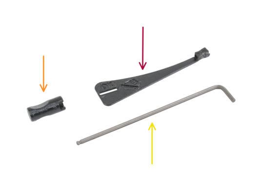
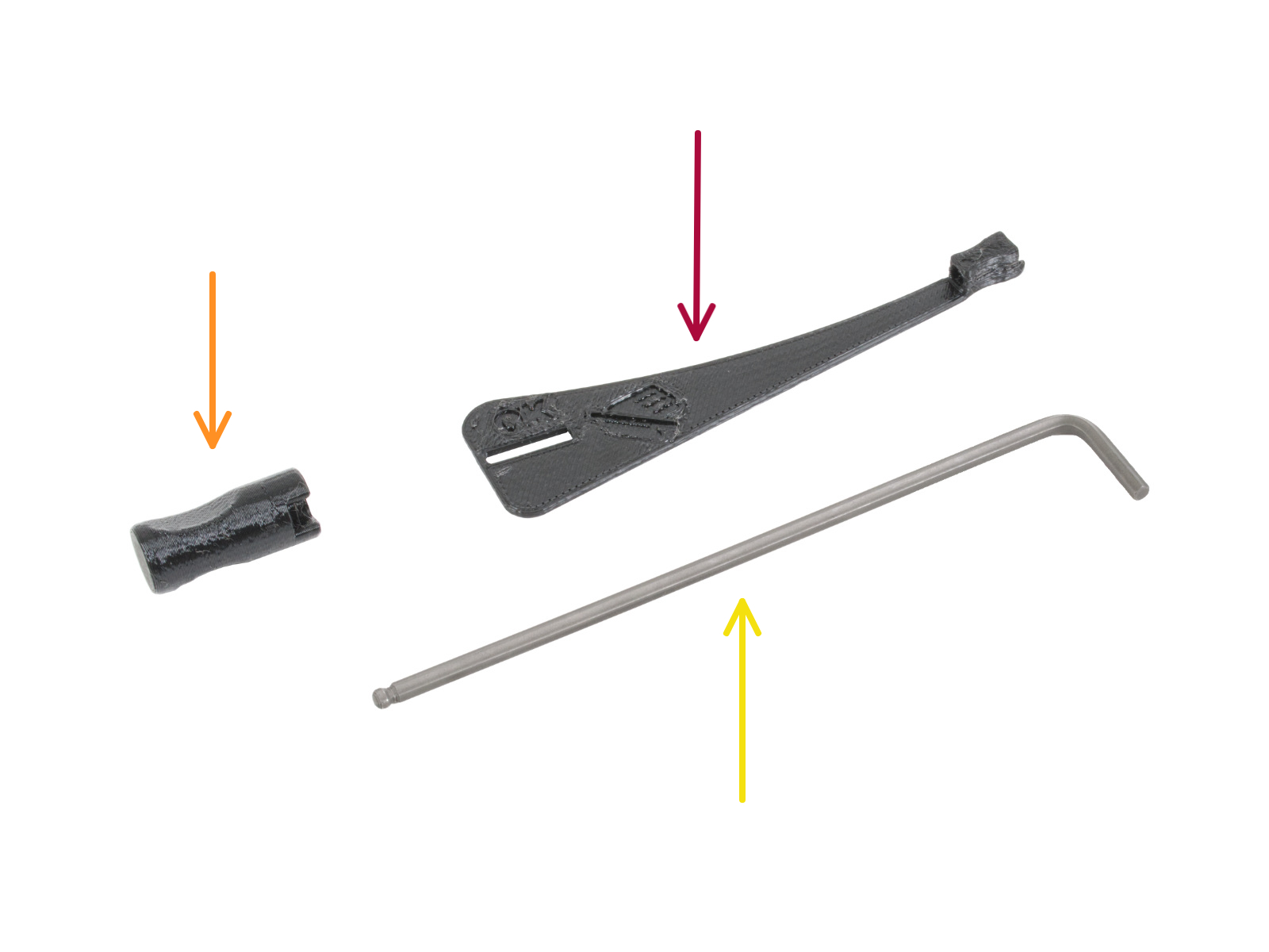
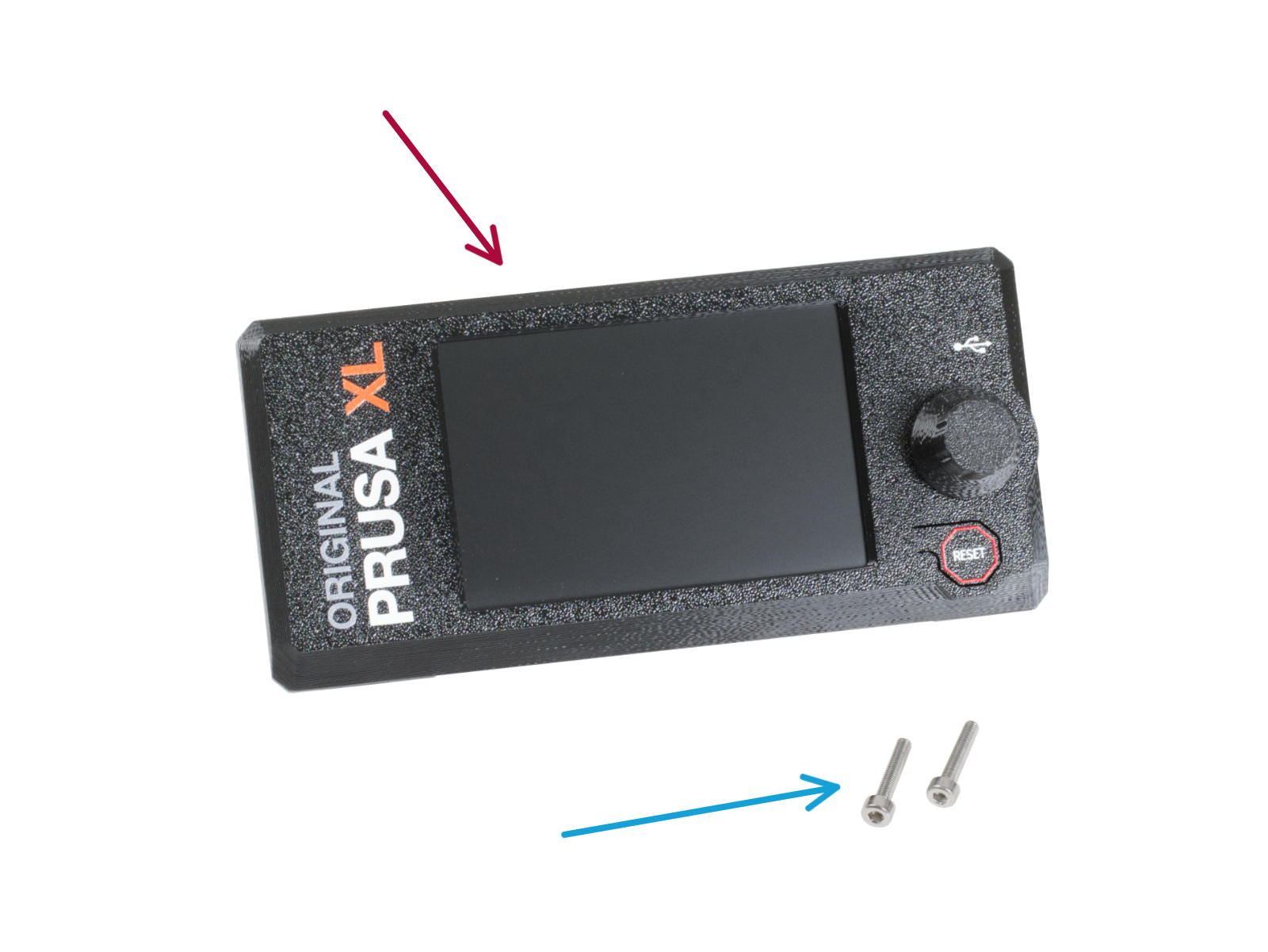
⬢For this guide, please prepare:
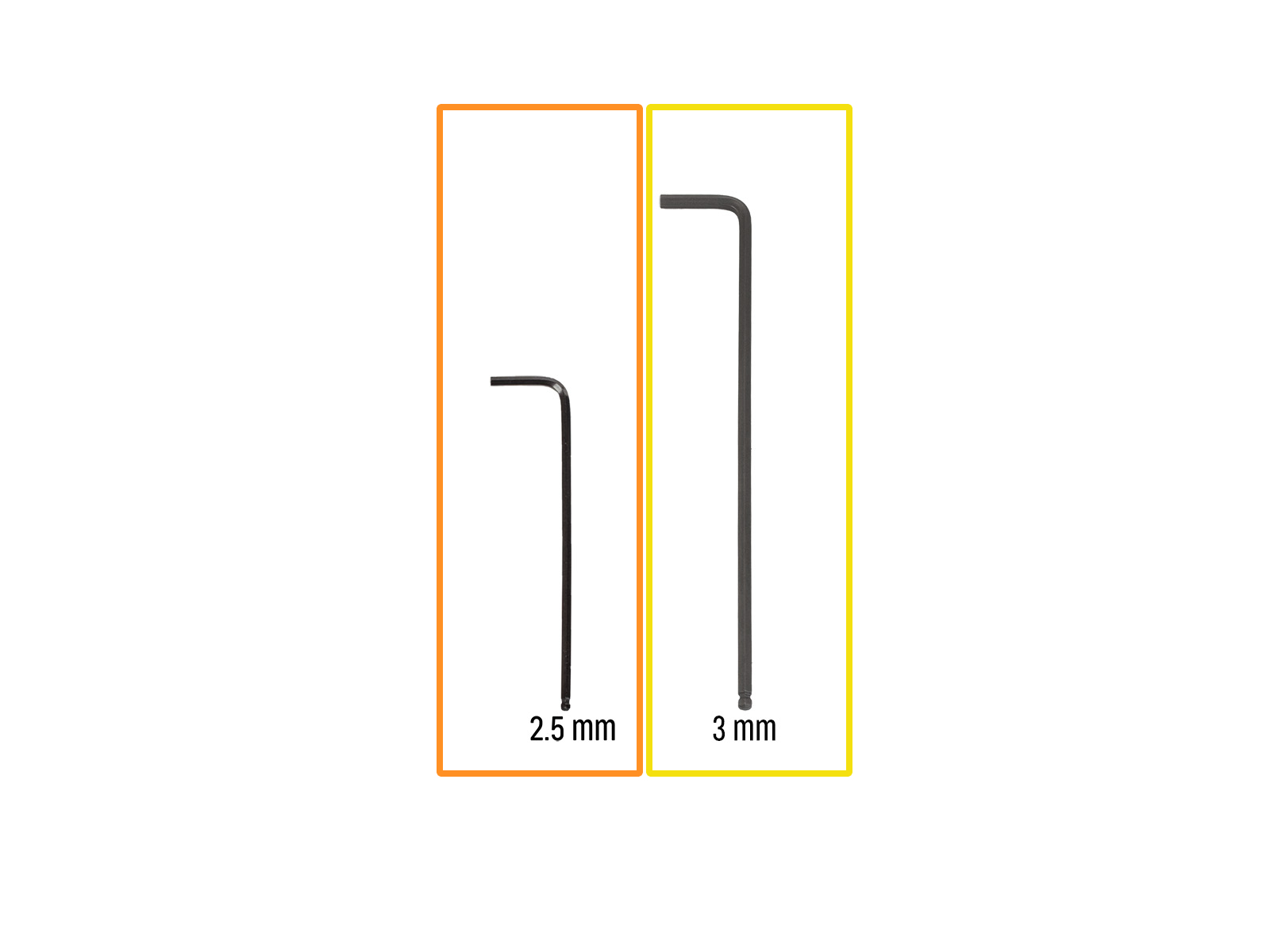
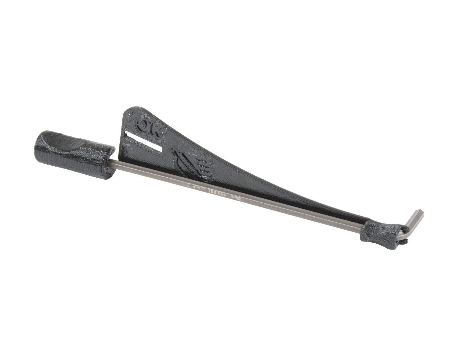
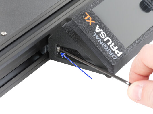
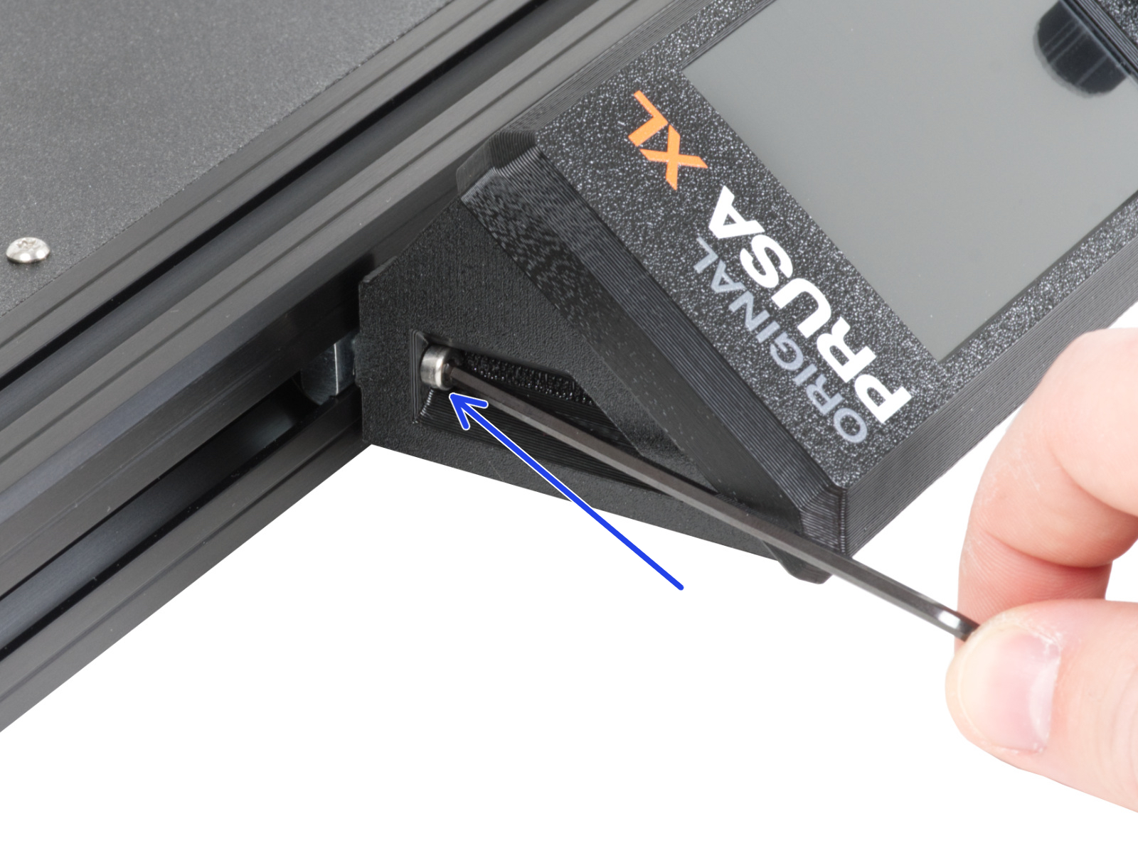
⬢2.5mm Allen key
⬢3mm Allen key


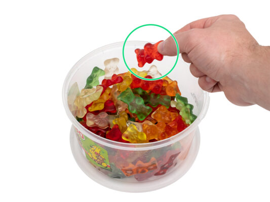

グミは1920年代にハンス・リーゲルというドイツのキャンディーメーカーによって初めて作られたことをご存知だろうか。


If you have a question about something that isn't covered here, check out our additional resources.
And if that doesn't do the trick, you can send an inquiry to [email protected] or through the button below.

