English
Login
3D printers
Materials
Parts & Accessories
For Business
Software
3D Models
Community
Help
Courses
Blog
Company
Support
Original Prusa i3 MK3S
Printer maintenance
How to replace a hotend thermistor (MK3S/MK3S+) | Begin assembly
1. Begin assembly
Step 1 of 17 (Chapter 1 of 17)
Contents
Comments
Difficulty
Moderate
Available languages
Begin assembly
Contents
Printer maintenance
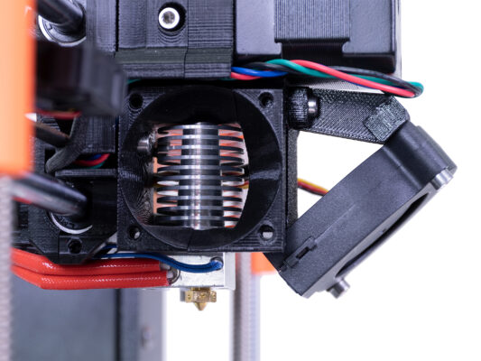
How to replace a hotend thermistor (MK3S/MK3S+)
Begin assembly
Introduction
Tools necessary for this guide
Preparing the printer
Disconnecting of the thermistor
Removing the textile sleeve
Extruder surgery
Removing the thermistor
New thermistor parts preparation
Thermistor installation
Guiding the hotend thermistor cables
Connecting the thermistor
Tightening the textile sleeve
Guiding the textile sleeve
Cable guiding
Final check
It's done!
How to replace a print fan (MK3S/MK3S+)
How to replace a hotend (MK3S/MK3S+)
How to replace an IR-sensor (MK3S/MK3S+)
How to replace a P.I.N.D.A. sensor (MK3S)
How to replace SuperPINDA (MK3S/MK3S+)
How to replace a hotend heater (MK3S/MK3S+)
How to replace a heatbreak/heatsink/heaterblock (MK3S+/MK3S/MK2.5S/MMU2S)
How to trim PTFE tube - Multi Material
How to post-process the printed parts
How to replace a heatbed thermistor (MK3S+/MK3S/MK2.5S/MK2S)
How to replace PSU on MK3 printers
How to replace a hotend PTFE tube (MK3S+/MK3S/MK2.5S/MMU2S)
How to replace a hotend thermistor (MK2S)
How to trim PTFE tube - Original Prusa printers
Maintenance tips
Replacing the PEI sheet on the (MK3S/MK3/MK2.5S/MK2.5)
Comments
Log in
to post a comment
No comments