English
Login
3D printers
Materials
Parts & Accessories
For Business
Software
3D Models
Community
Help
Courses
Blog
Company
Support
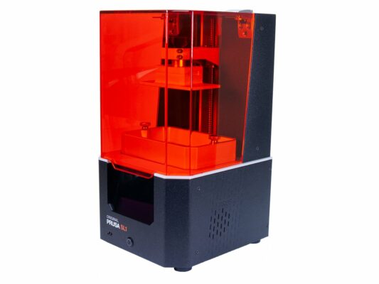
Original Prusa SL1
Printer maintenance
How to replace a blower fan (SL1) | Begin assembly
1. Begin assembly
Step 1 of 21 (Chapter 1 of 9)
Contents
Comments
Difficulty
Moderate
Available languages
Begin assembly
Contents
Printer maintenance
How to replace a blower fan (SL1)
Begin assembly
Introduction
Tools necessary for this chapter
Preparing the printer
Removing the cover
Disconnecting the blower fan
Removing the UV LED assembly
Releasing the blower fan cable
Removing the blower fan assembly
Blower fan disassembly
Blower fan parts preparation
Blower fan gasket
Fan assembly
Blower assembly
Mounting the fan assembly
Guiding the fan cable
Guiding the fan cable
Mounting the UV LED assembly
Connecting the power button
Assembling the cover
It is done!
How to replace an optical sensor (SL1)
How to replace the print display (SL1)
How to replace the power button (SL1/SL1S)
How to replace the A64 board (SL1)
How to replace the USB connector (SL1/SL1S)
How to post-process the printed parts
How to replace a UV LED assembly (SL1)
How to replace a filter (SL1/SL1S)
Comments
Log in
to post a comment
No comments