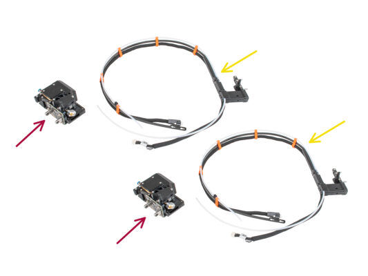
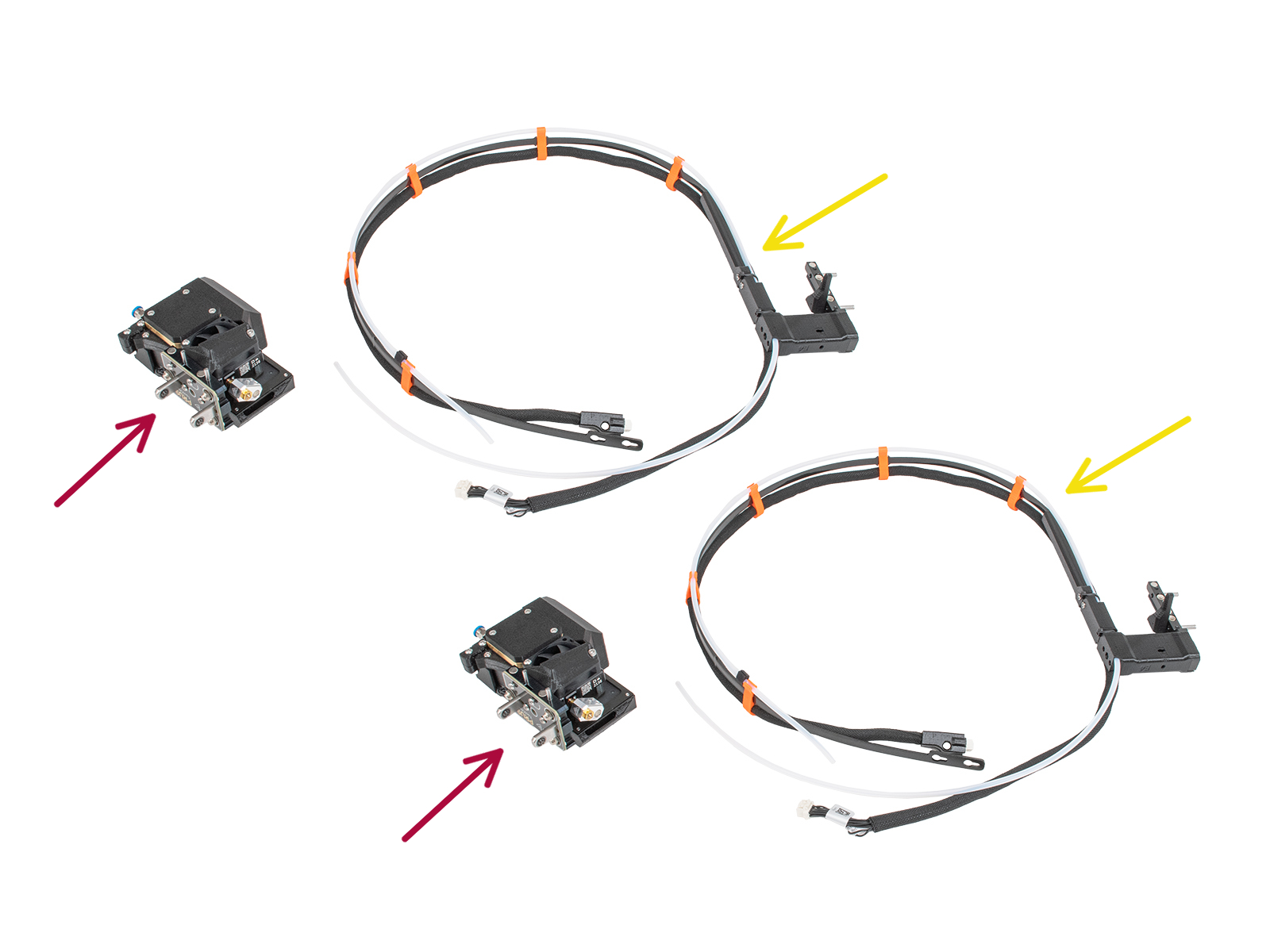
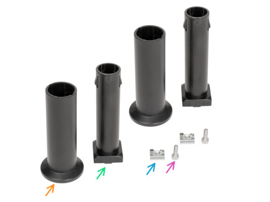
⬢For this chapter, please prepare:
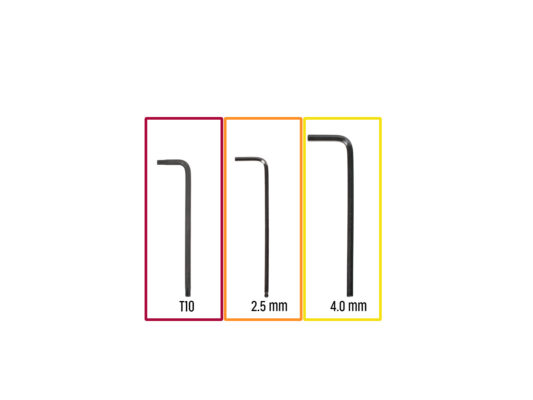
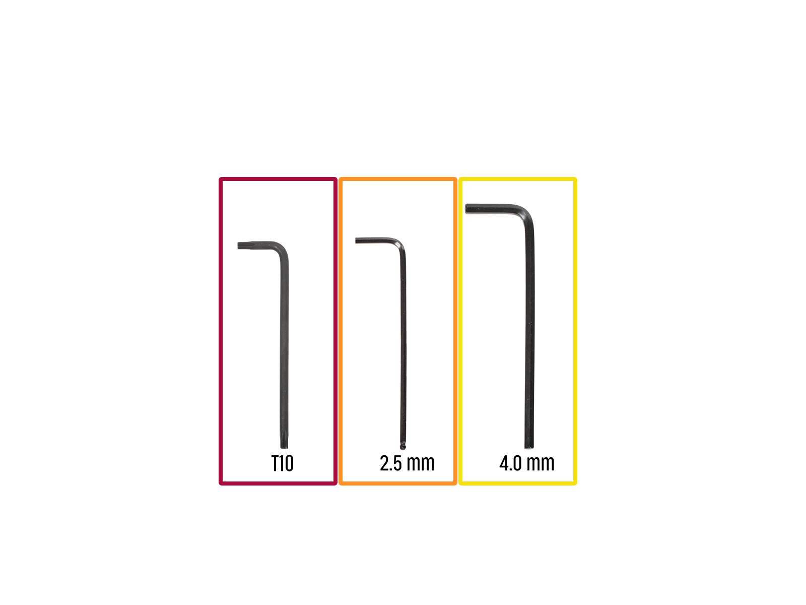
⬢T10 Torx key
⬢2.5 mm Allen key
⬢4.0 mm Allen key
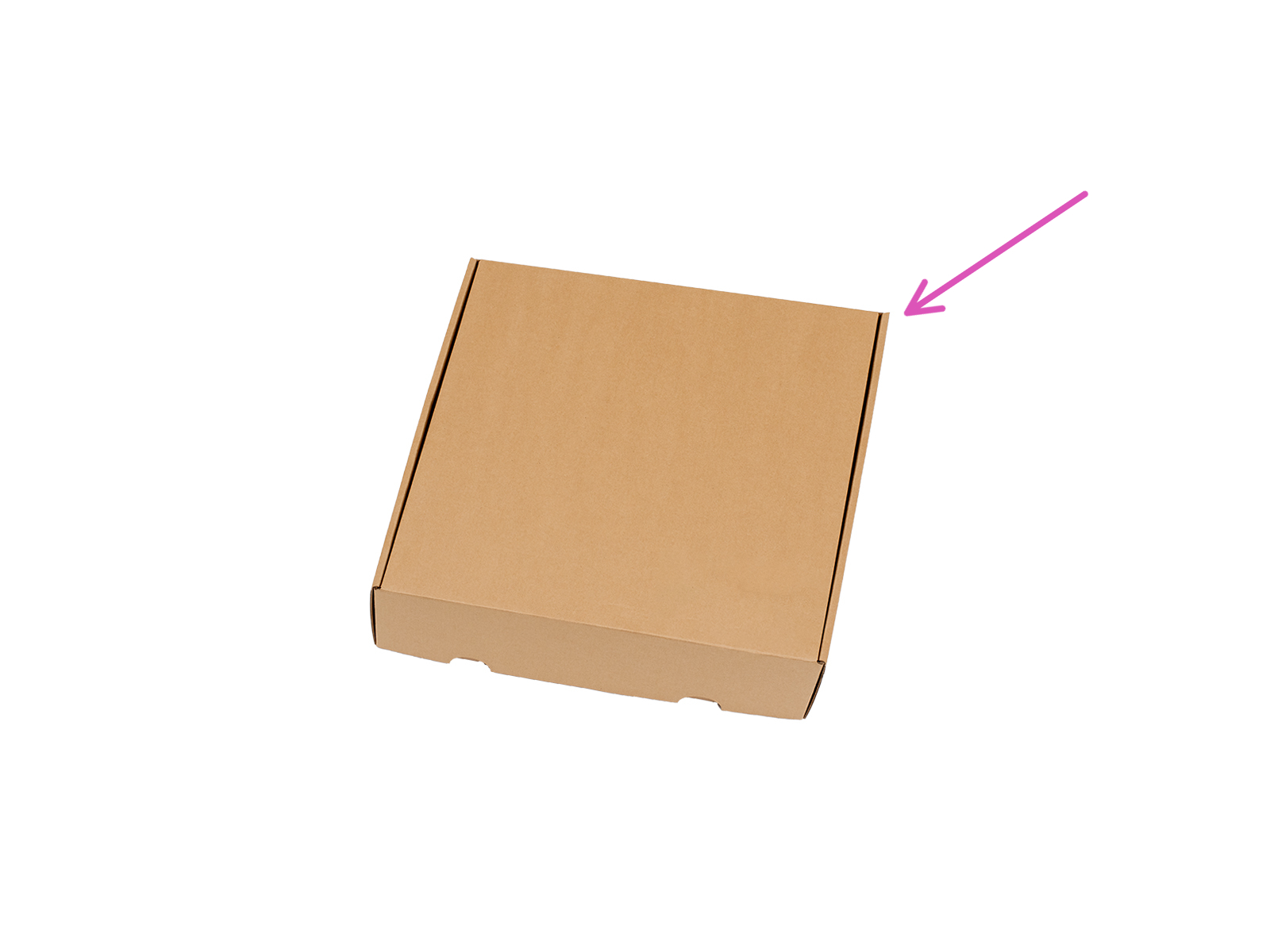
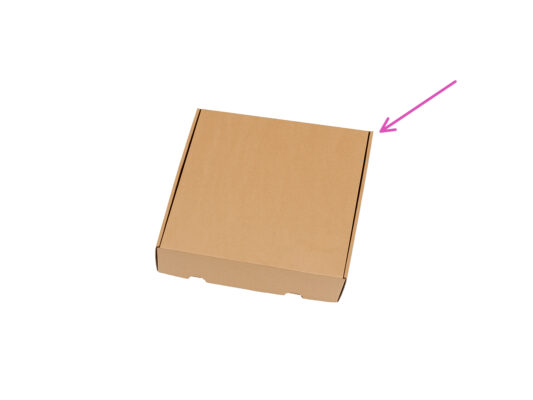
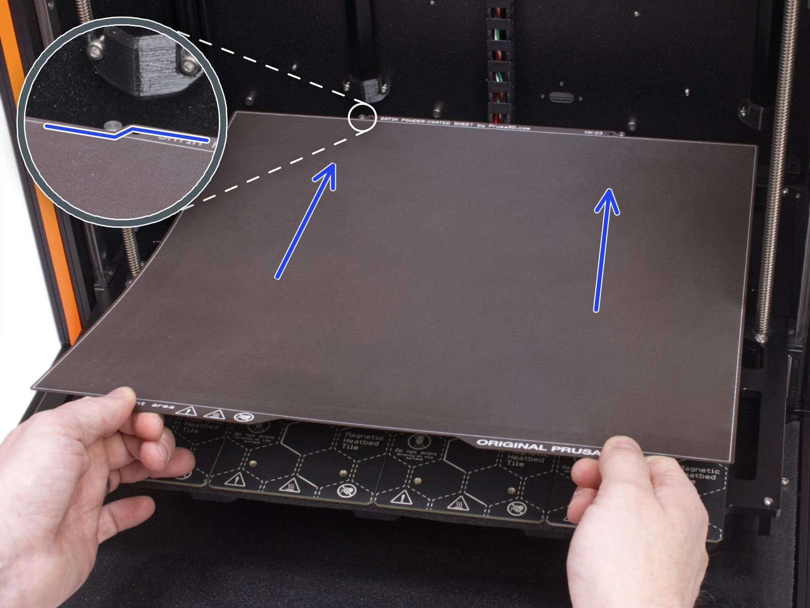
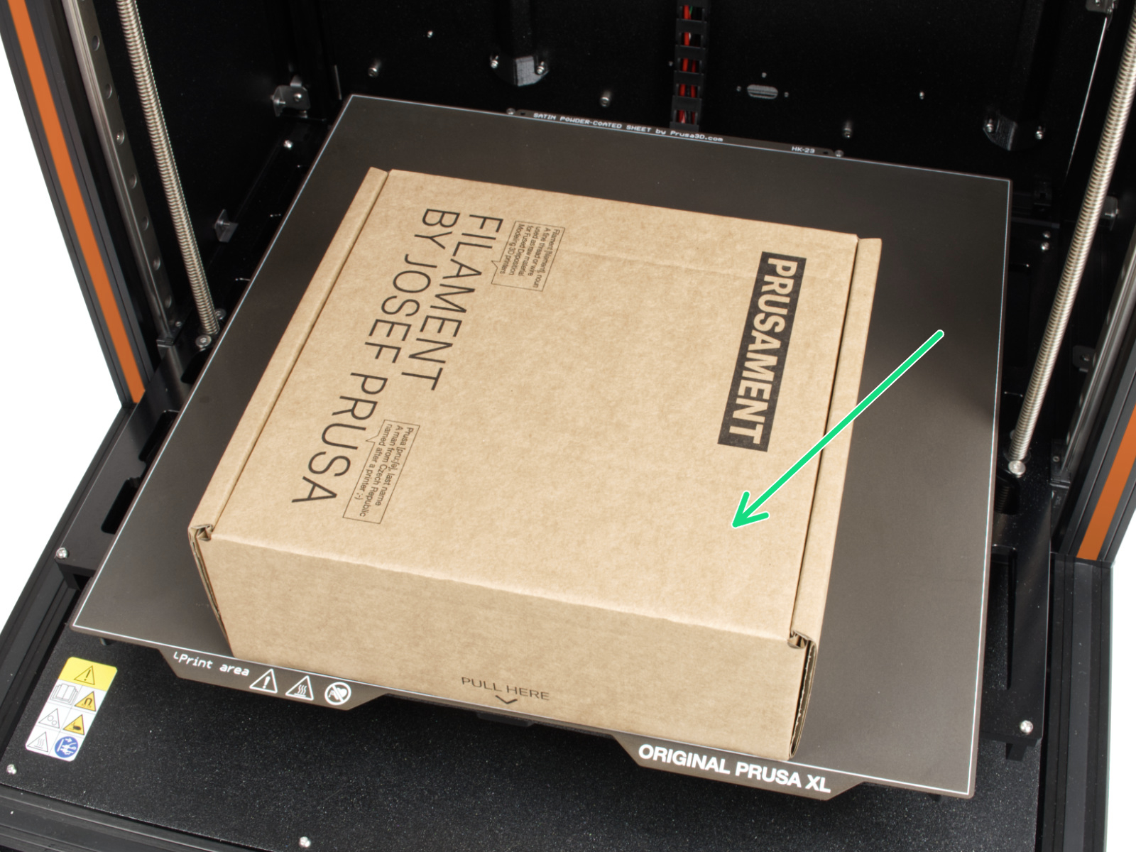
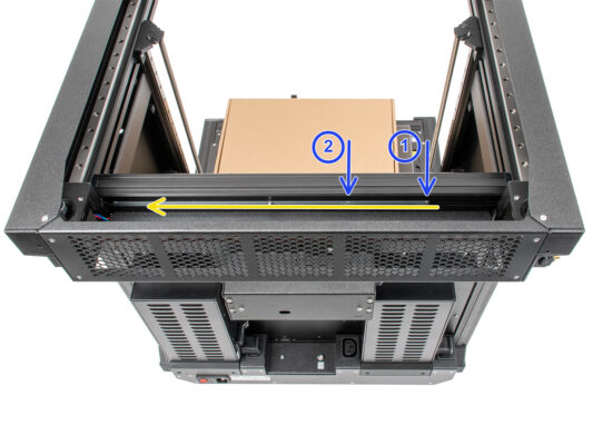
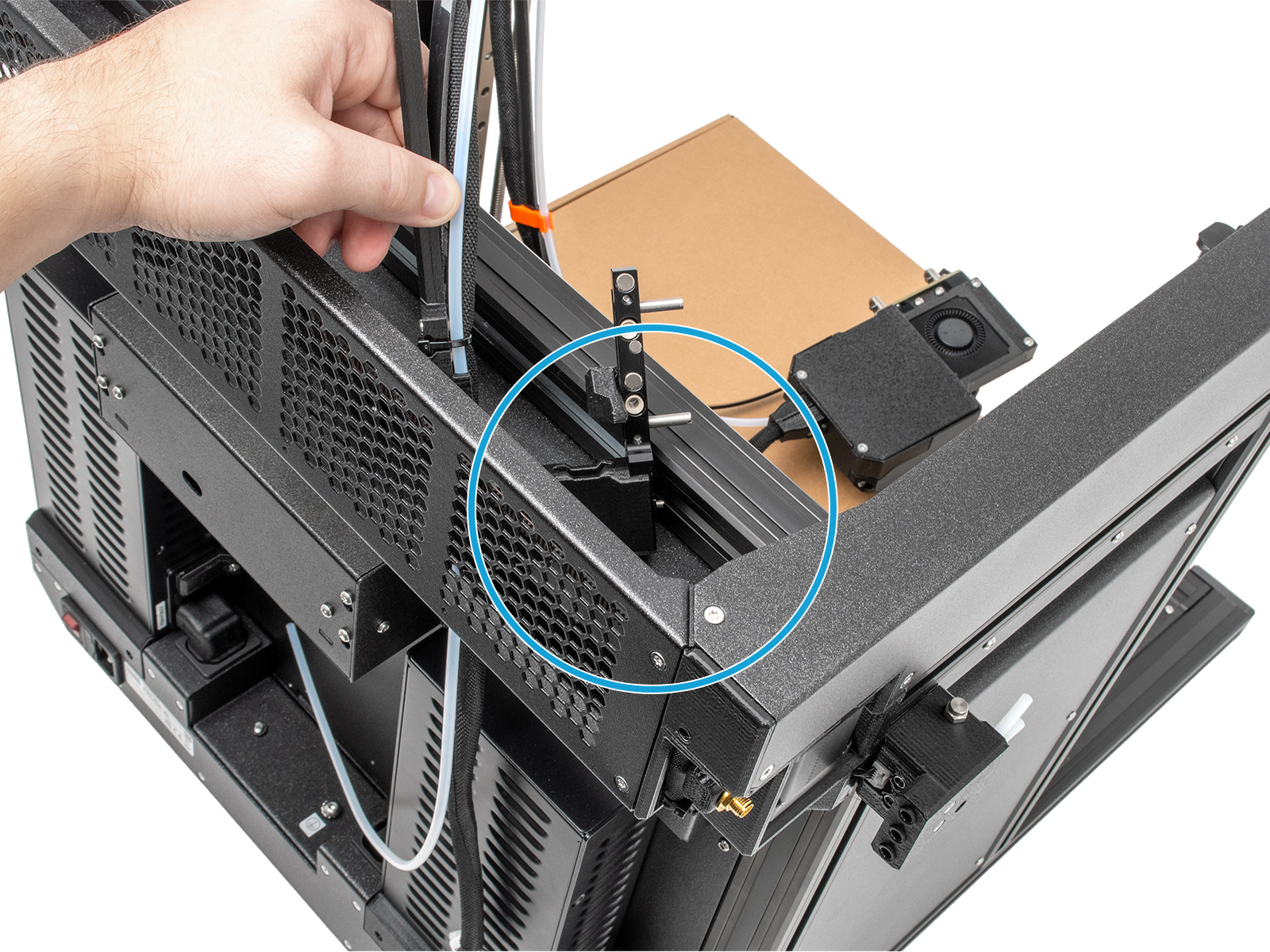
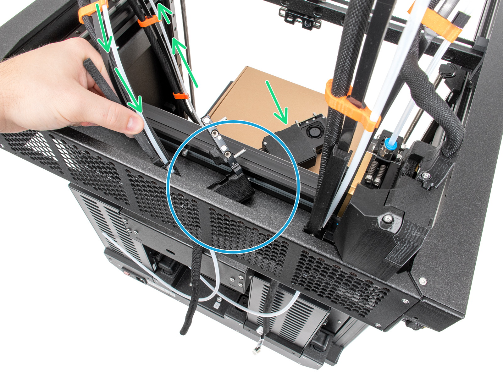
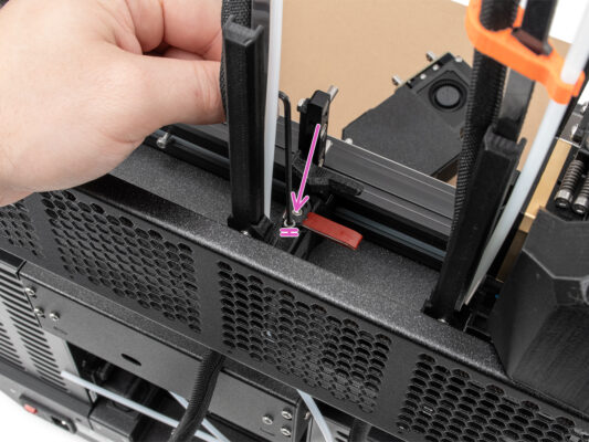
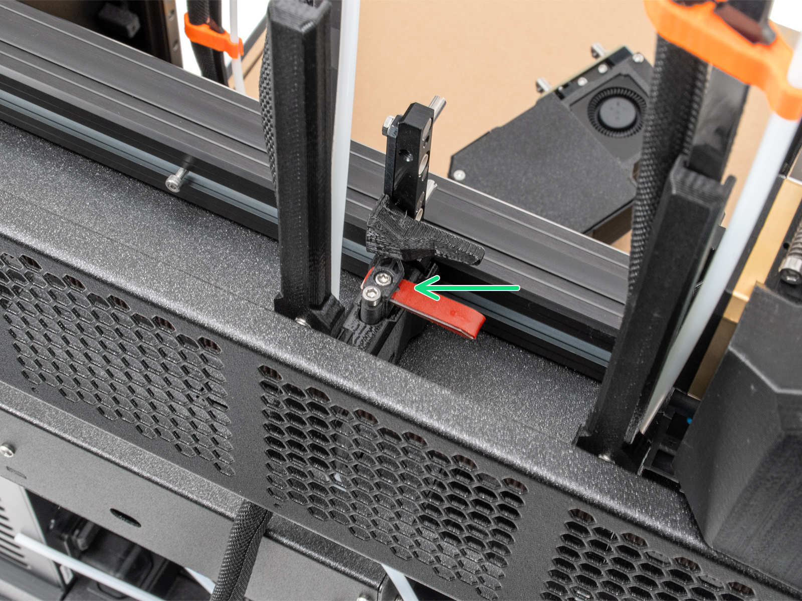
⬢A cardboard box is to be used as heatbed protection during the setup. Hint: you can use the Nextruder box shipped with your printer.


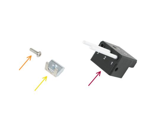


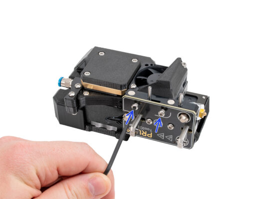
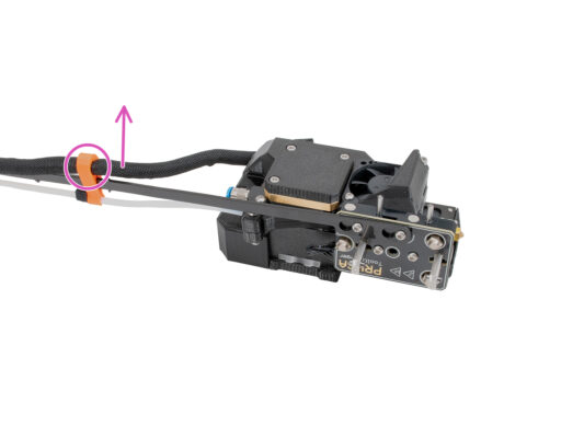

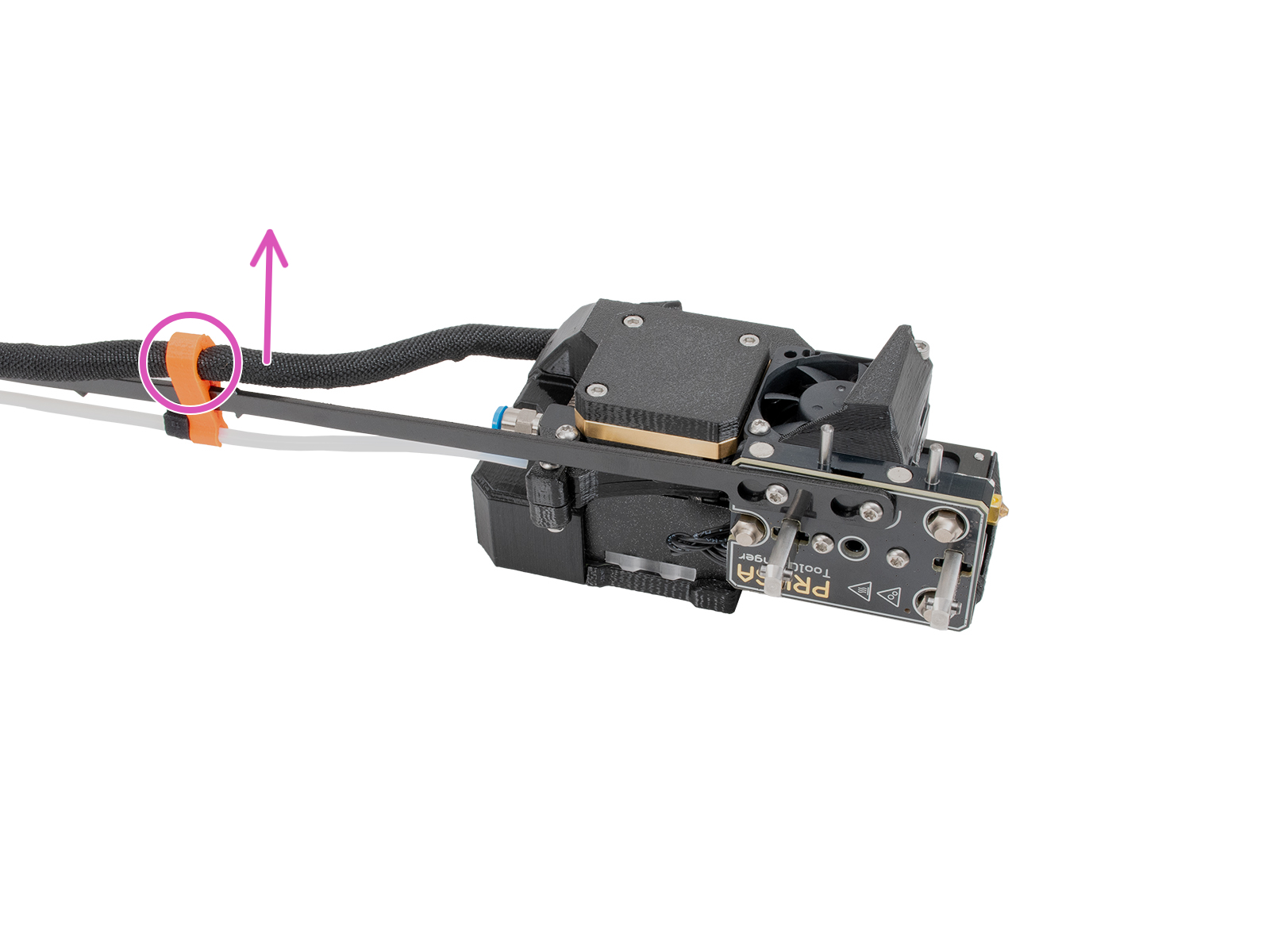
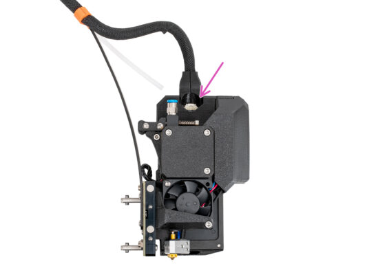
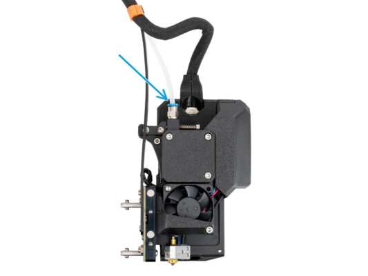
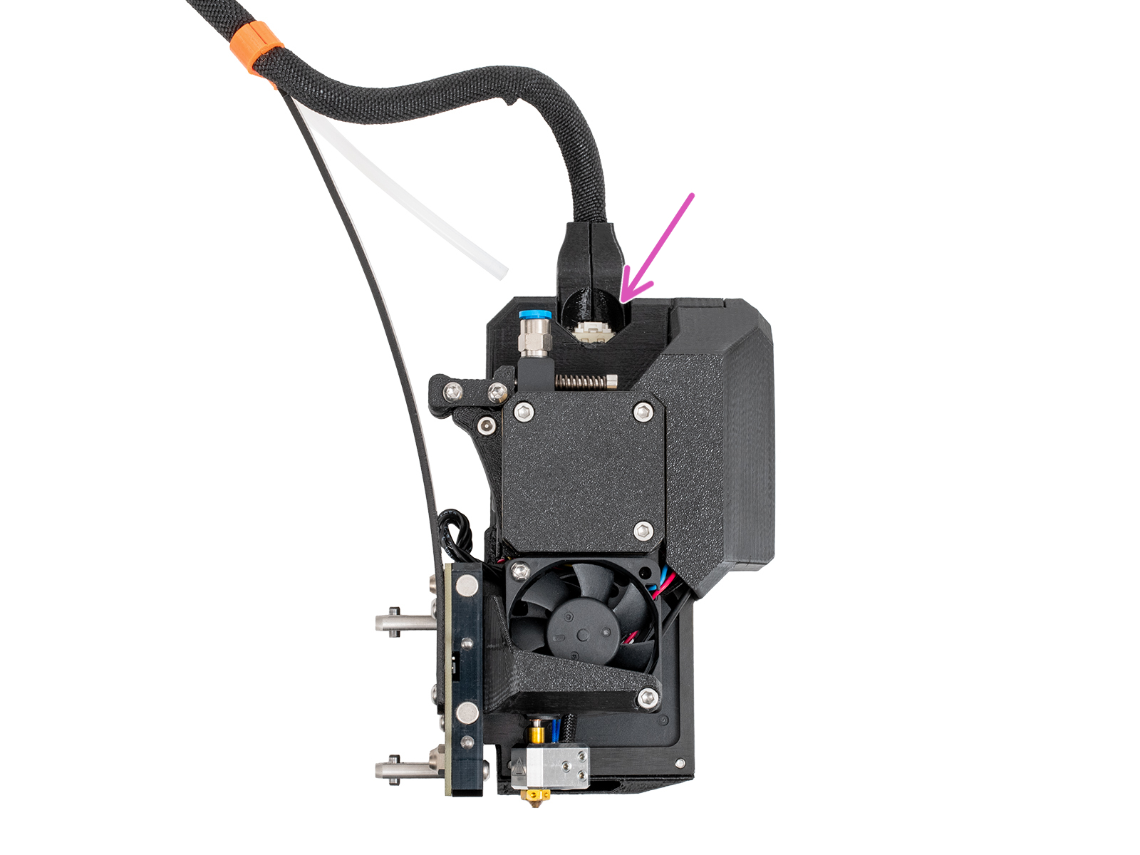

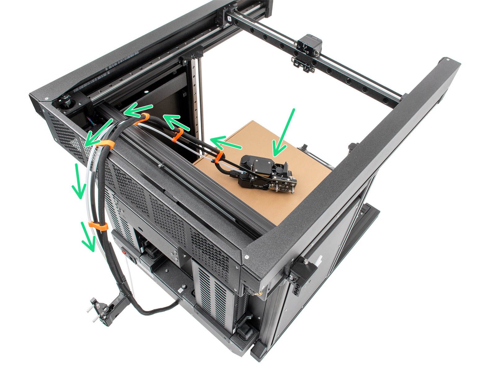
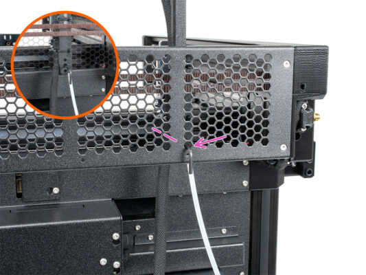
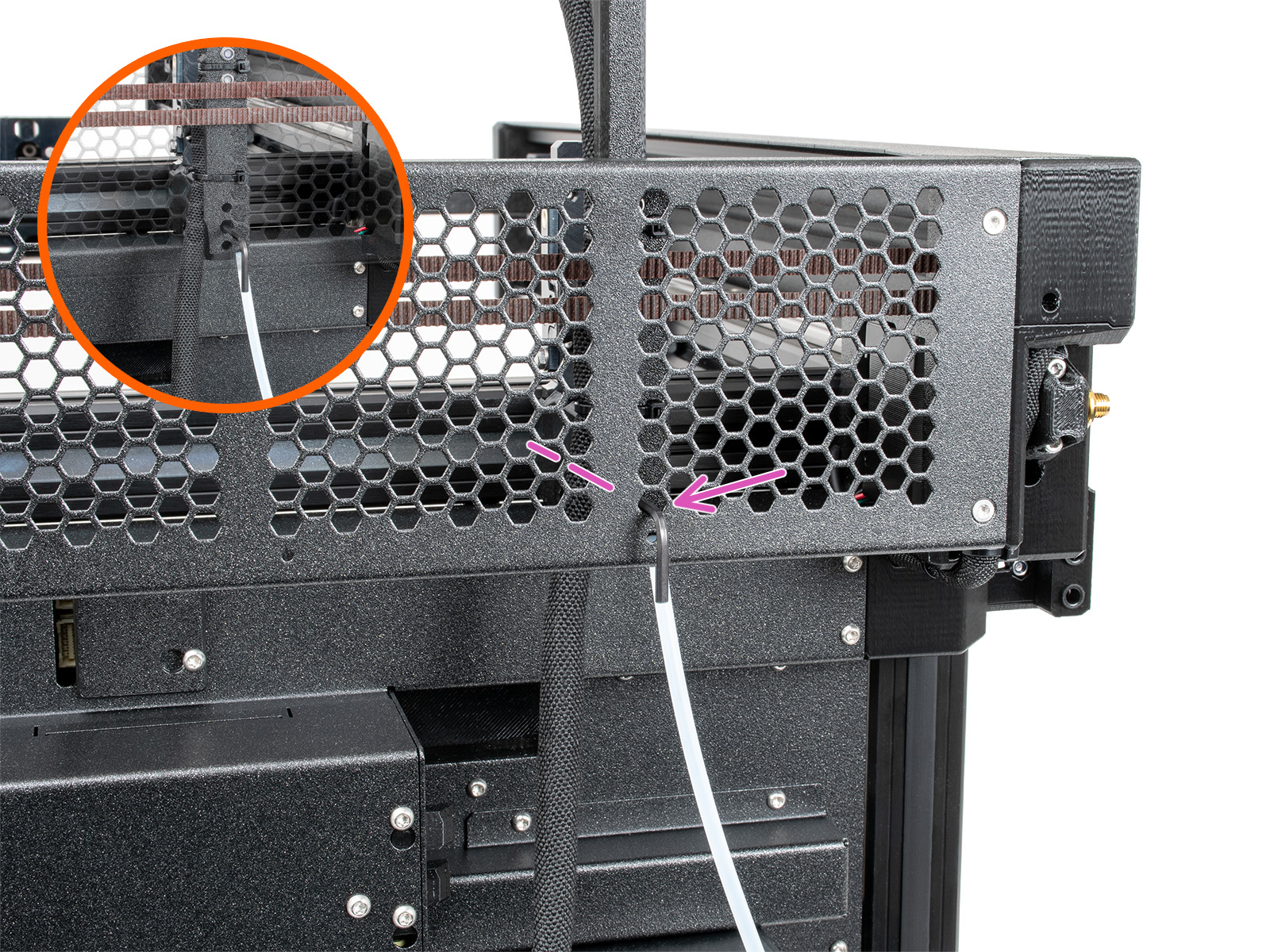
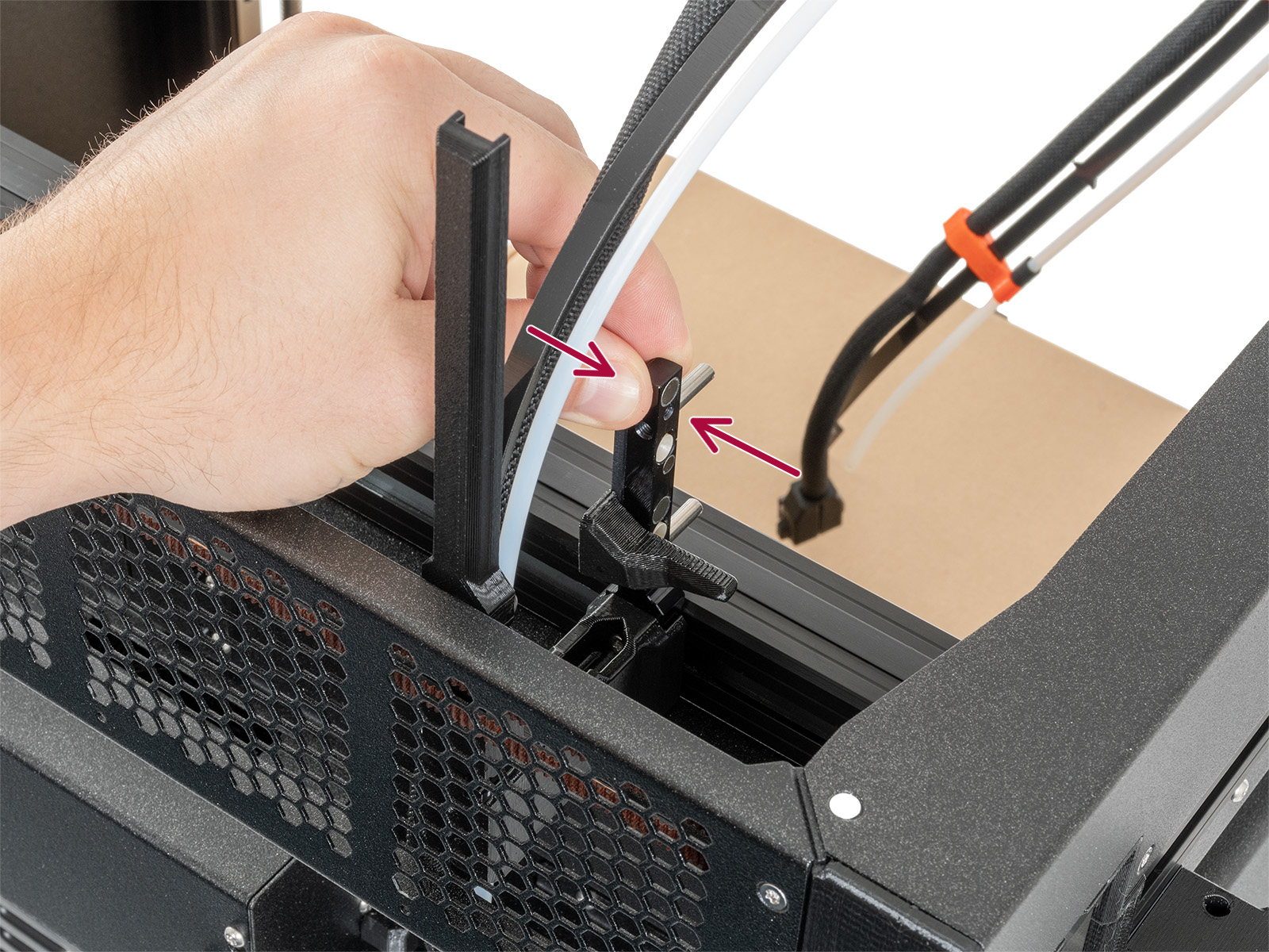
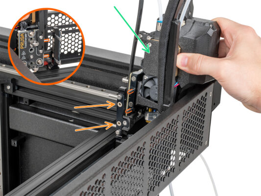
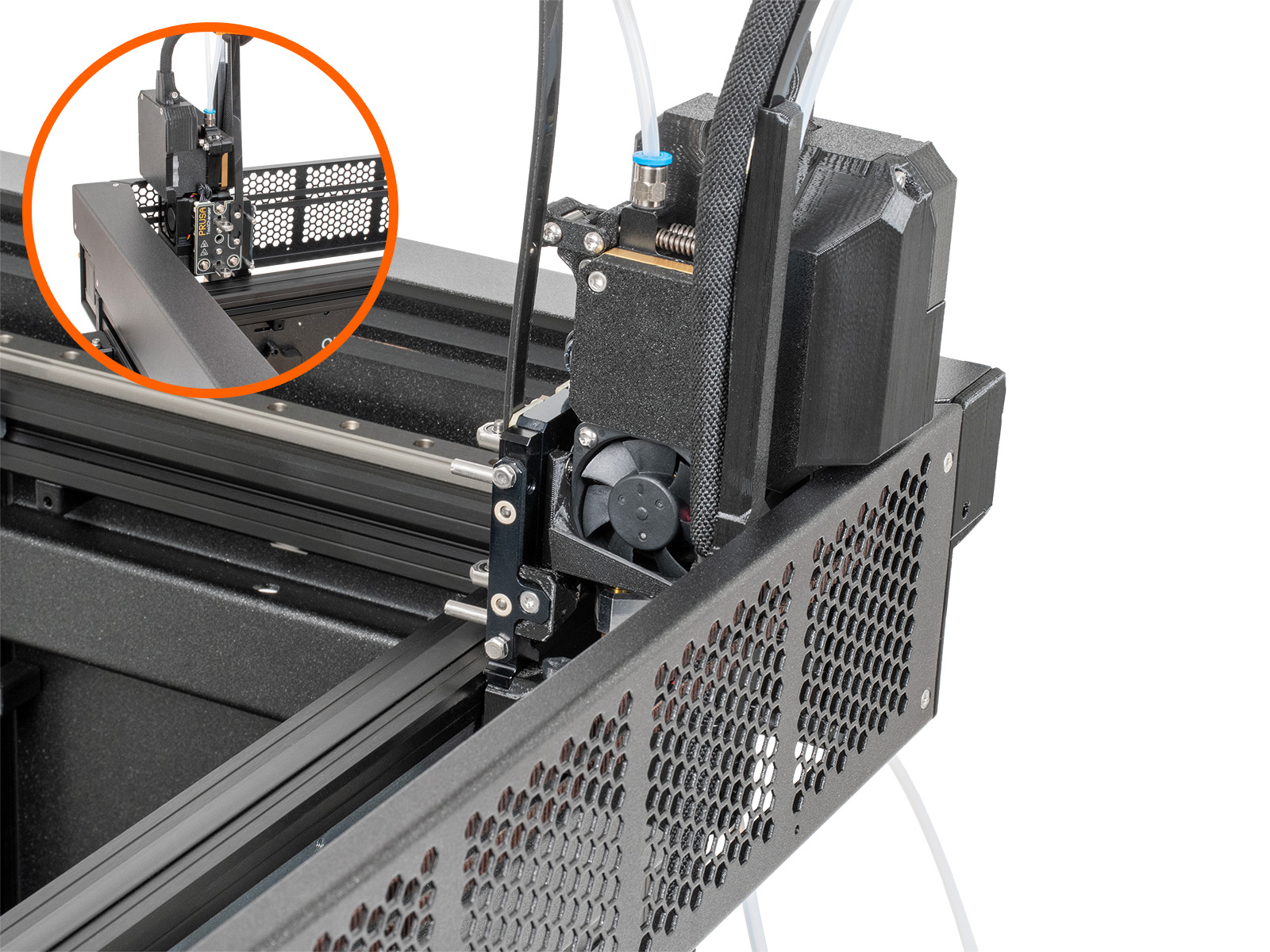
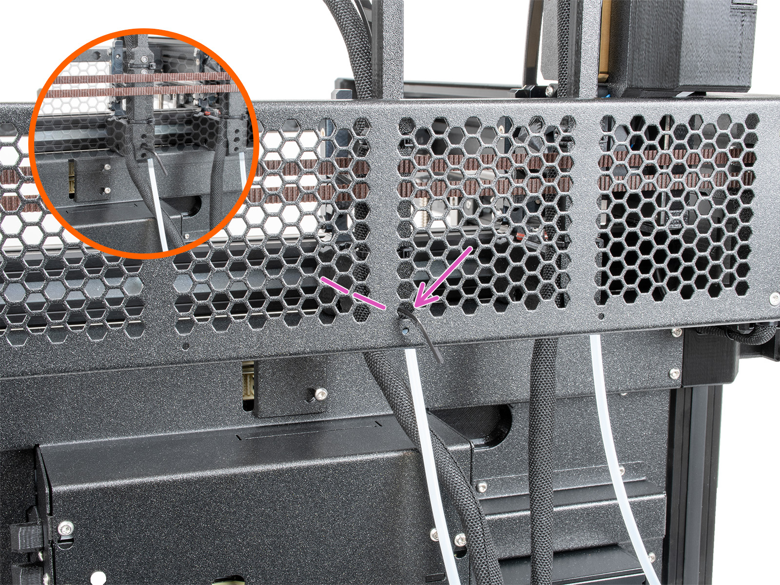
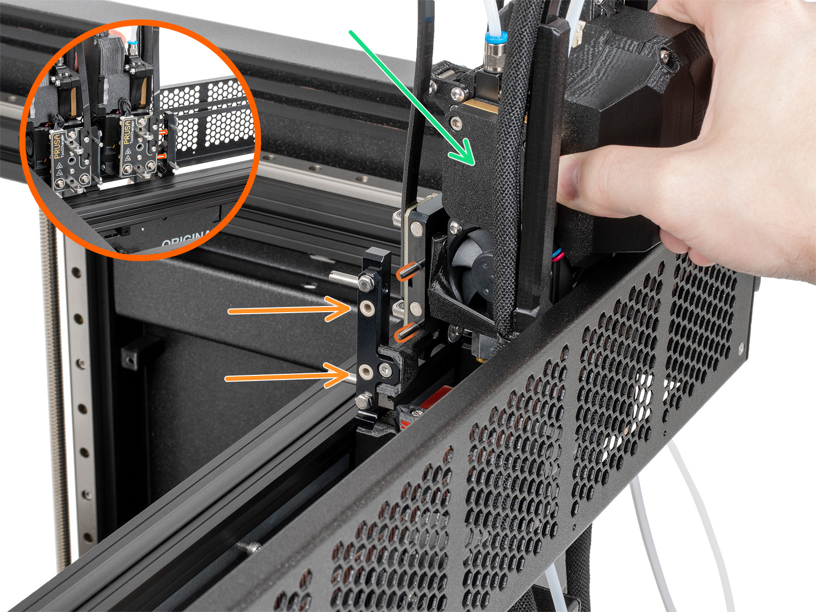
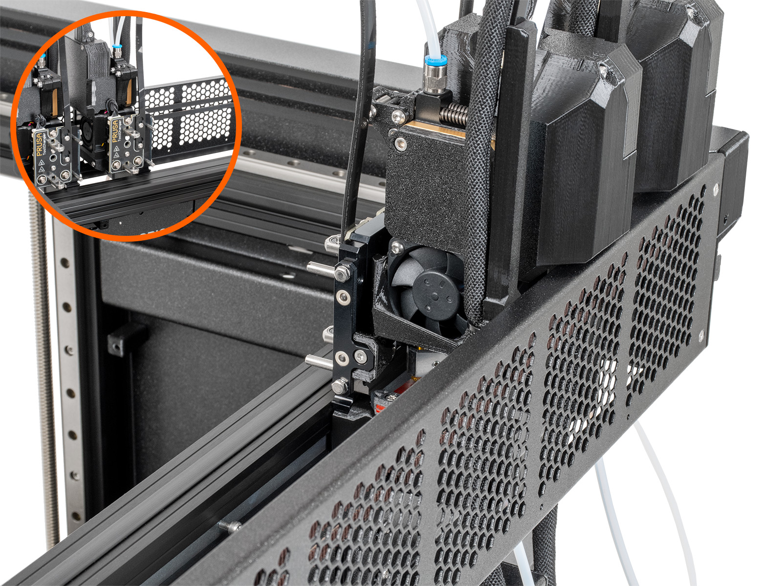
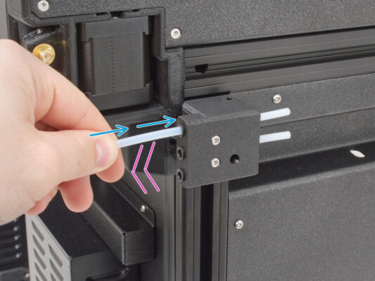
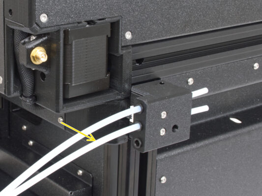
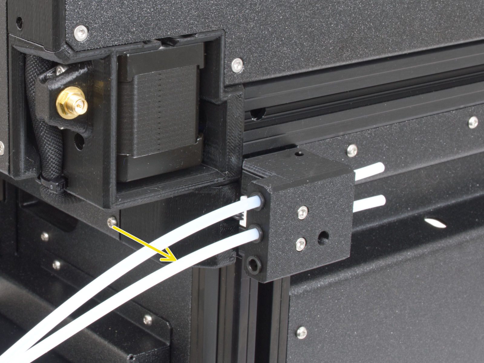
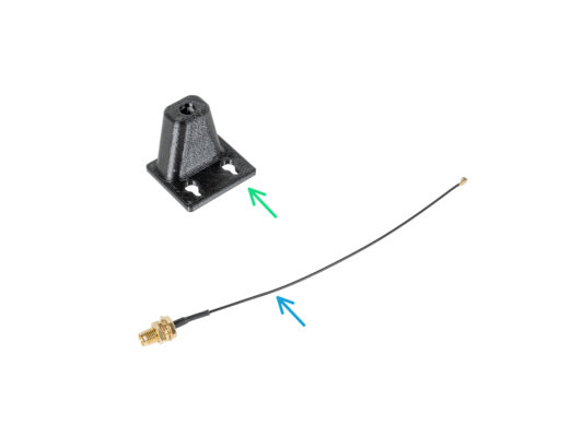
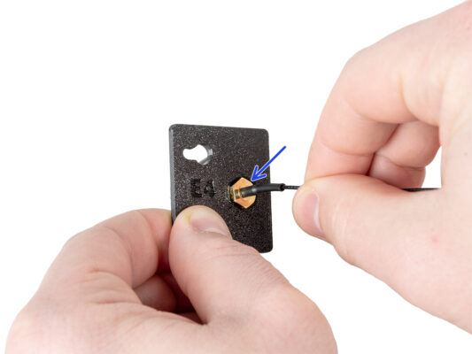
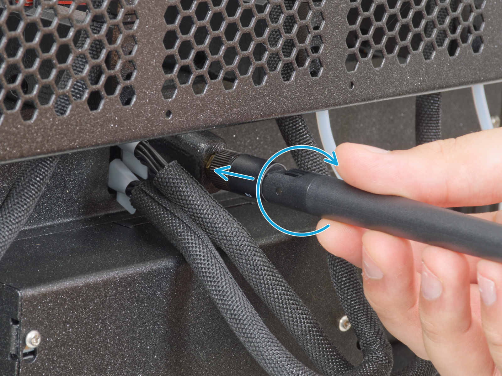
Insert the semi-transparent PTFE tube into the fitting QSM-M5 on the Nextruder.
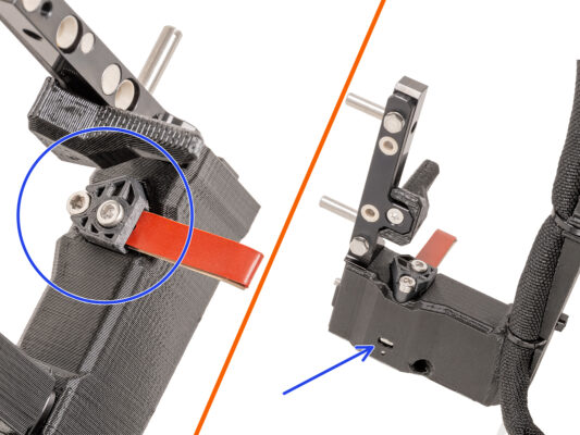

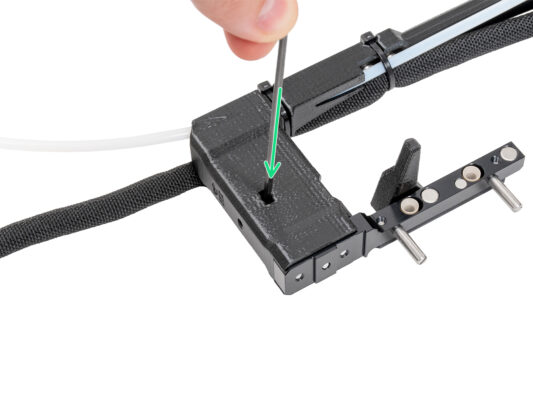

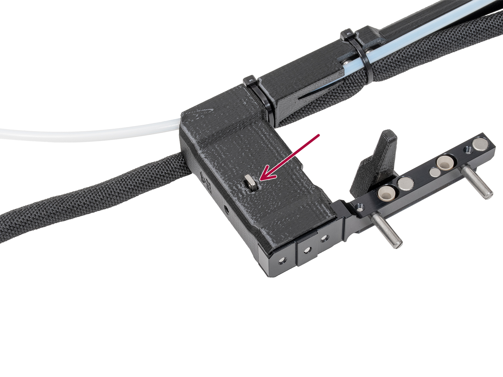

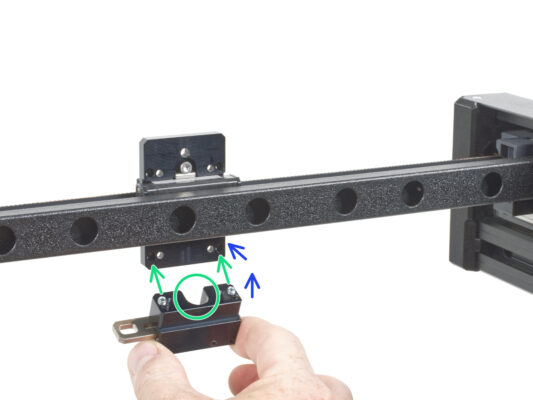
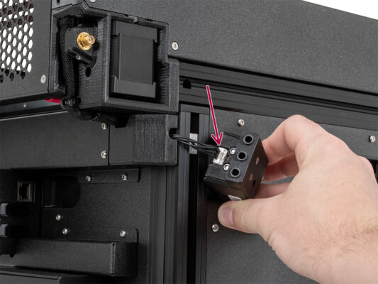
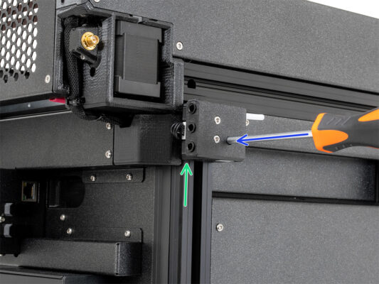
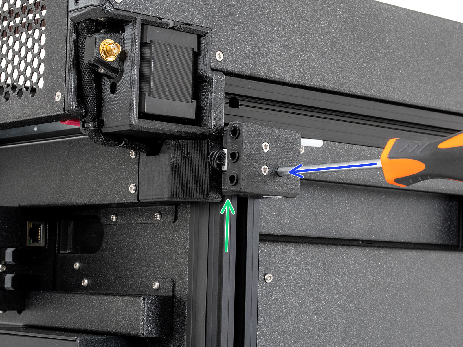
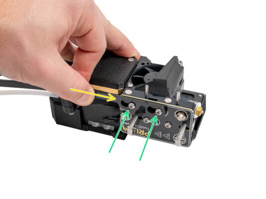
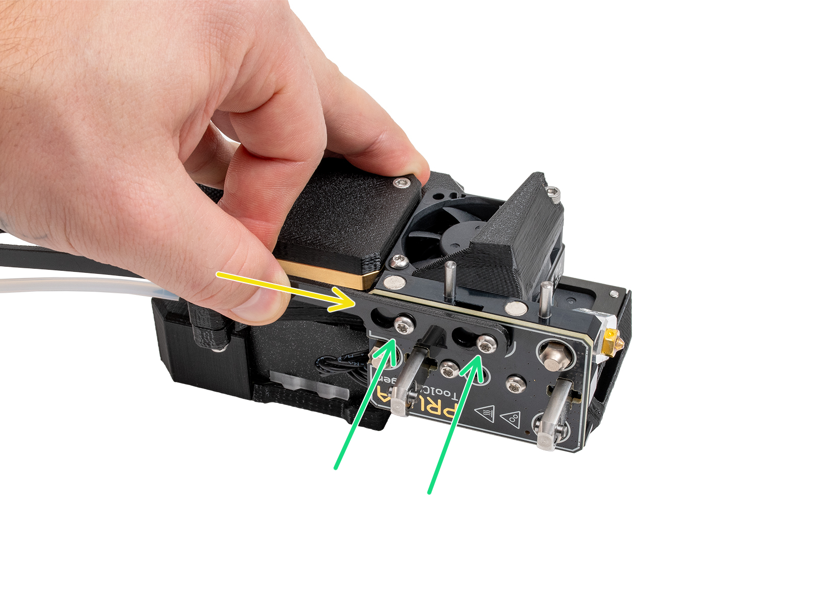
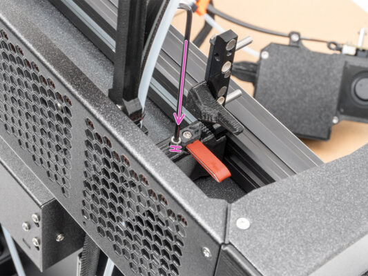
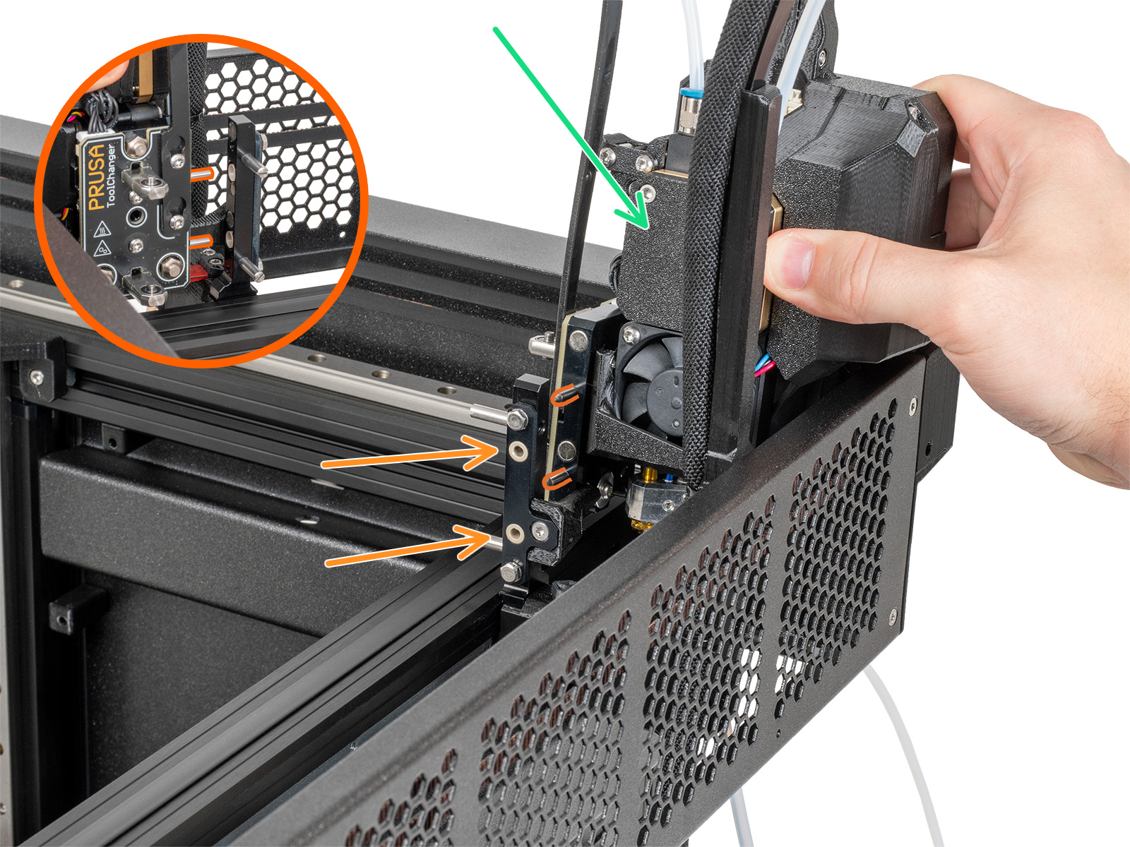
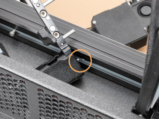
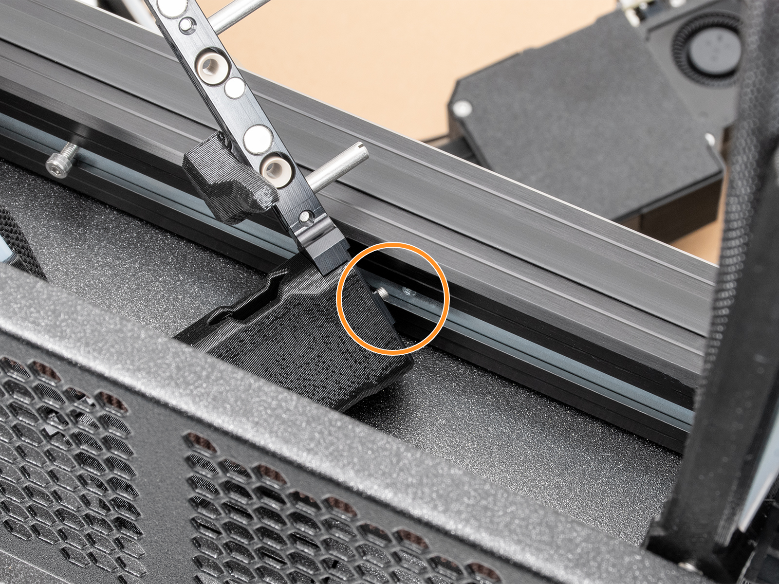
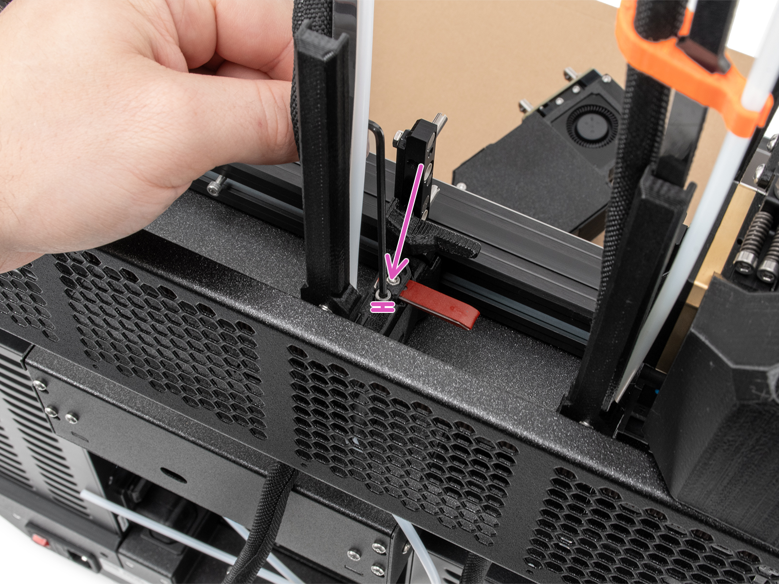
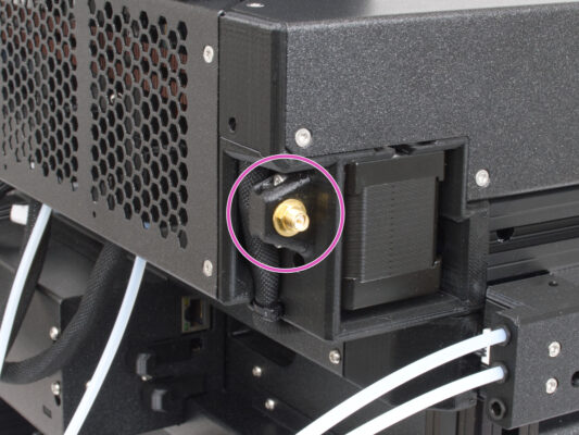
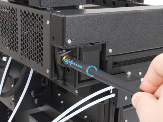
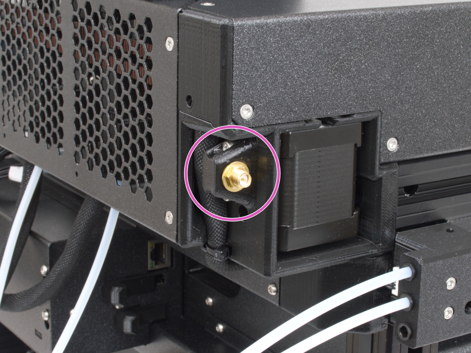
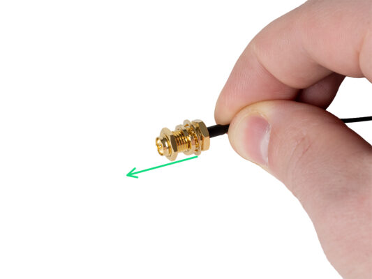
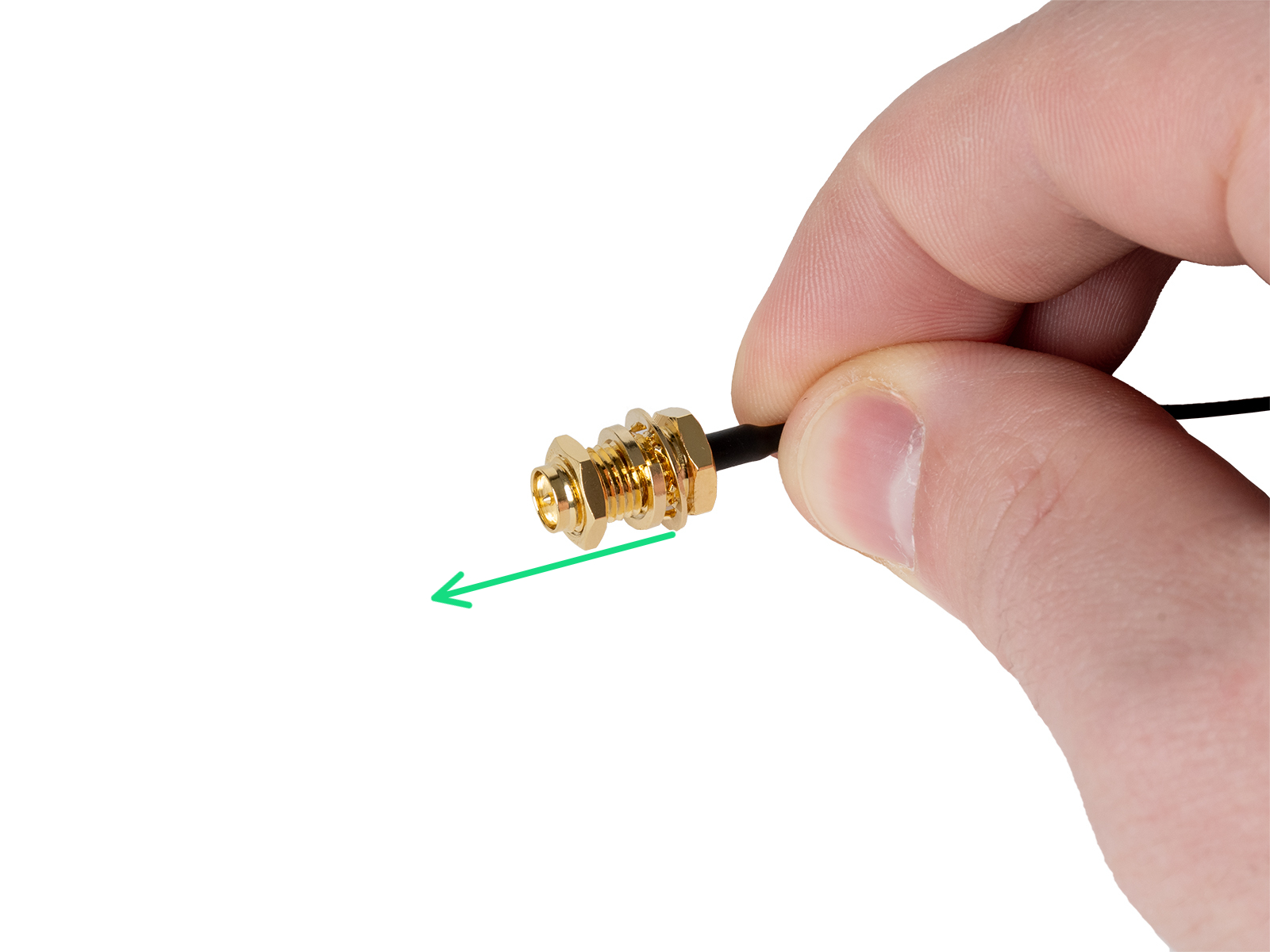
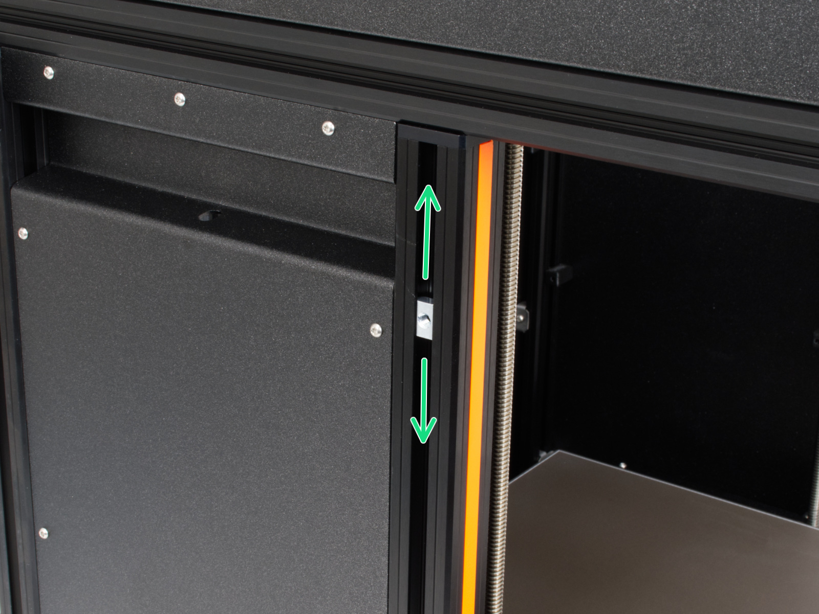
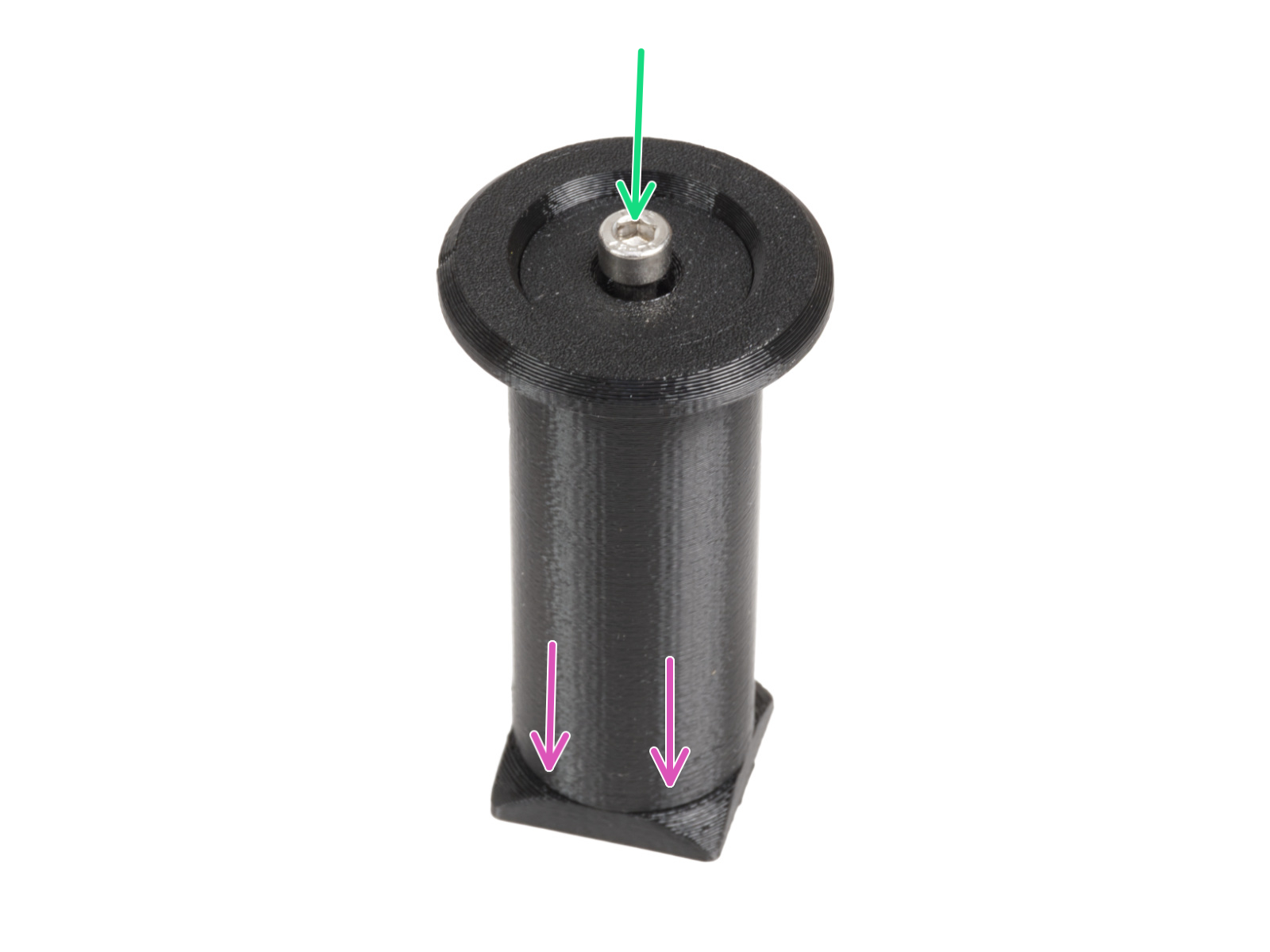
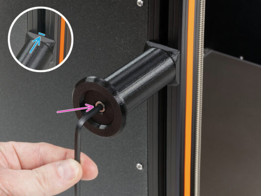
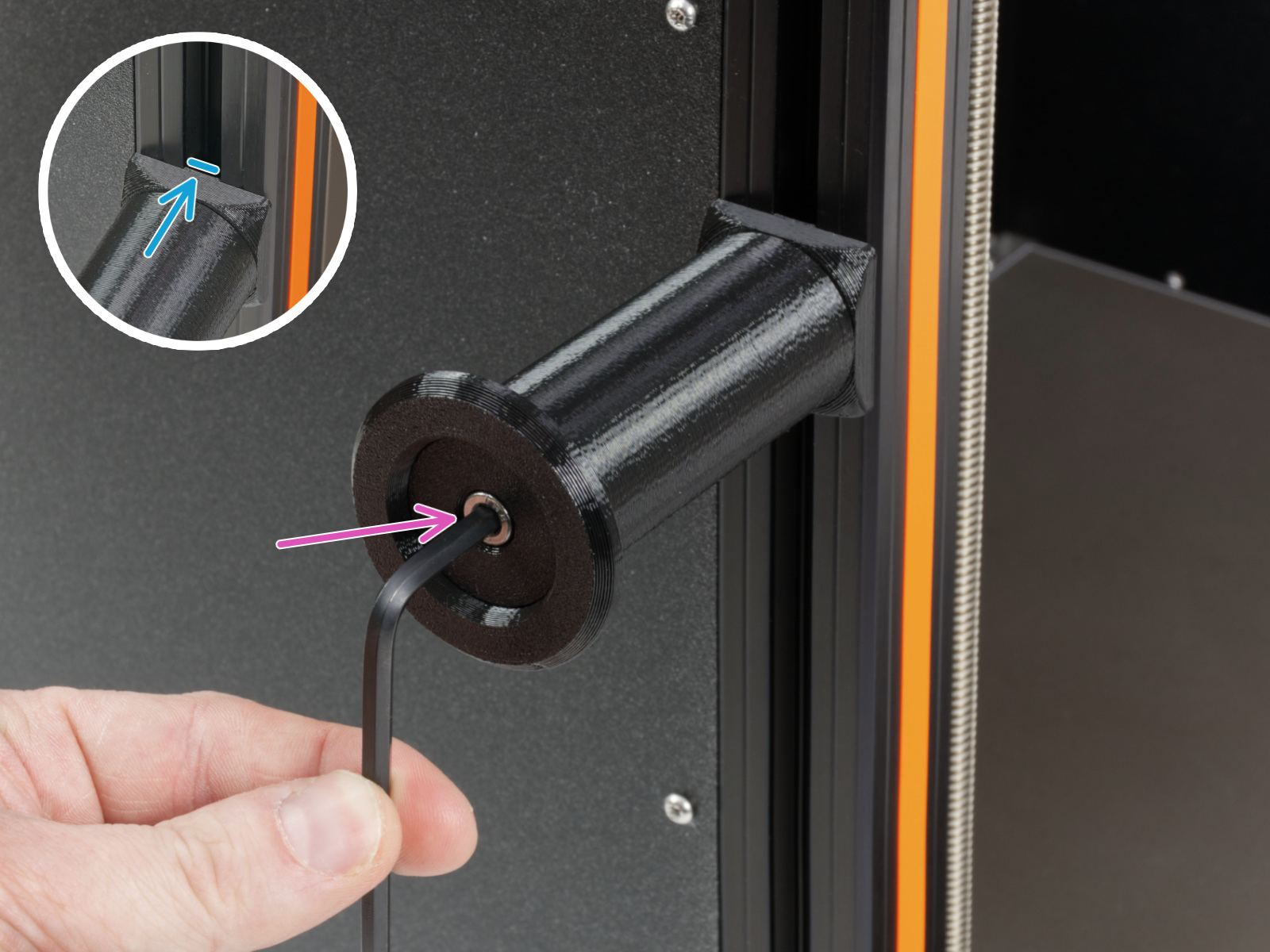
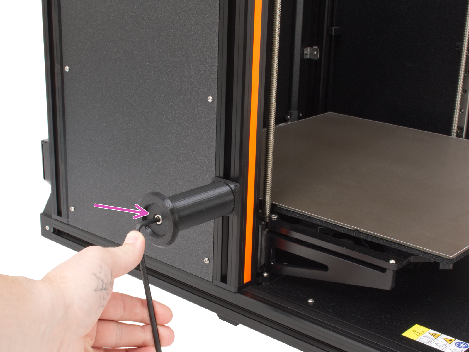
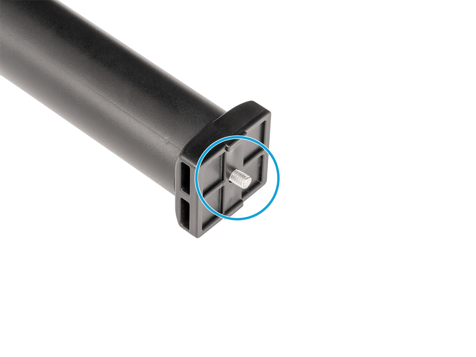
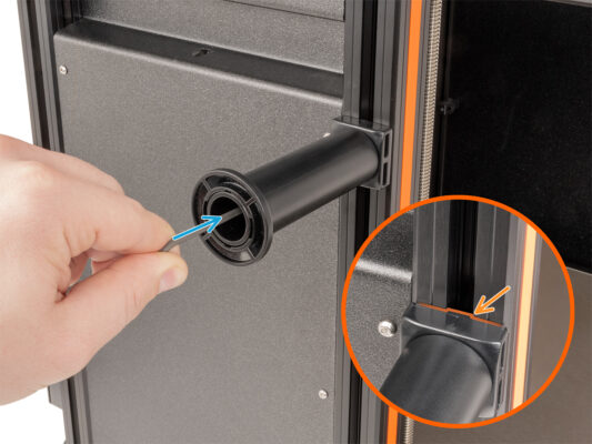
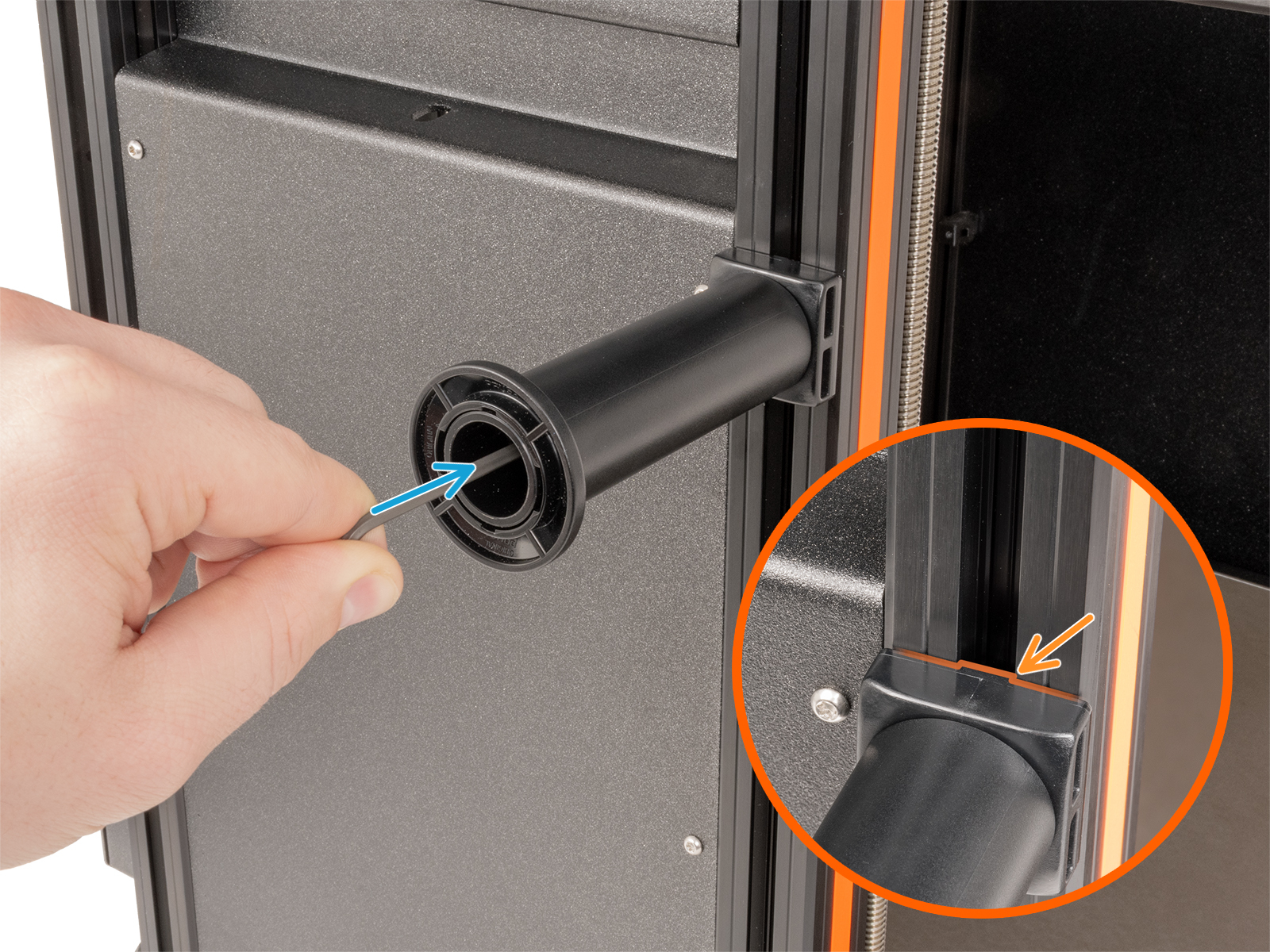
Make sure the nut is pushed into the dock all the way. If not use the Allen key to push the nut into the Nextruder dock.


If you have a question about something that isn't covered here, check out our additional resources.
And if that doesn't do the trick, you can send an inquiry to [email protected] or through the button below.

