Polski
Login
Drukarki 3D
Materiały
Części i akcesoria
Oprogramowanie
Modele 3D
Branże
Społeczność
Pomoc
Akademia
Blog
Firma
Wsparcie
Original Prusa i3 MK2S
Montaż zestawu Original Prusa i3 MK2S
4. Z-axis assembly | Przygotuj potrzebne narzędzia
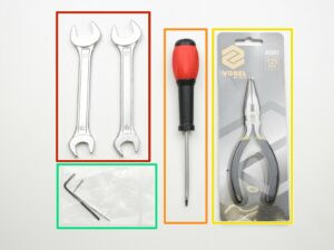
1. Przygotuj potrzebne narzędzia
Krok 1 z 27 (Rozdział 4 z 9)
Spis treści
Komentarze
⬢
Klucze 13/17 mm
⬢
Płaski wkrętak 3.6 mm
⬢
Szczypce spiczaste
⬢
Klucze imbusowe 2.5 mm i 1.5 mm
Loading...
Dalej
Spis treści
Montaż zestawu Original Prusa i3 MK2S
1. Wstęp
2. Y-axis assembly
3. Montaż osi X
4. Montaż osi Z
Przygotuj potrzebne narzędzia
Montaż uchwytów silników osi Z
Montaż silników osi Z
Montaż nakrętek trapezowych
Znalezienie prętów o odpowiedniej długości
Montaż osi X
Ułożenie przewodów
Montaż osi Y
Montaż paska osi X, część 2
Prowadzenie paska przez uchwyt koła pasowego osi X
Poluzowanie silnika
Naprężanie paska osi X, część 2
WIDEO dla kroków 16-24
Gotowe!
Assembling the Y-axis
Assembling the X-axis belt, part 1
Assembling the X-axis belt, part 2
The X-axis belt idler guide
The X-axis belt carriage guide
The X-axis belt motor guide
Loosening the motor
Tightening the X-axis belt, part 1
Tightening the X-axis belt, part 2
Tensioning the belt
VIDEO for steps 16-24
Adjusting tension screws
All done!
5. Montaż ekstrudera
6. Montaż wyświetlacza LCD
7. Montaż zasilacza i podgrzewanego stołu
8. Montaż elektroniki
9. Sprawdzenie przed uruchomieniem
Komentarze
Zaloguj się
, aby dodać komentarz
Brak komentarzy