日本語
Login
3Dプリンター
マテリアル
部品 & アクセサリー
法人向け
ソフトウェア
3Dモデル
コミュニティ
ヘルプ
コース一覧
ブログ
会社概要
サポート
Original Prusa XL
Original Prusa XL [進行中の翻訳] (1.06)
3. Printer set up | この章に必要な道具
1. この章に必要な道具
ステップ 1 / 53 (章 4 / 6)
内容
コメント
⬢
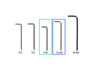
この章で、準備するもの:
⬢
TX10 トルクス・キー
⬢
2.5 mm 六角レンチ
⬢
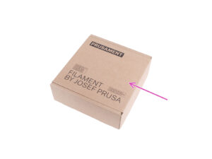
段ボール箱:組み立ての際にヒートベッド保護として使用します。ヒント:プリンタに同梱されているプルーサメントボックスを使用できます。
Loading...
次
内容
Original Prusa XL [進行中の翻訳]
1. はじめに
2A. プリンタの開梱
2B. プリンタの開梱
3. プリンタのセットアップ
この章に必要な道具
ネクストルーダーケーブルアセンブリの情報
Variant A - Nextruder cable bundle assembly: parts preparation
Variant A - Nextruder cable bundle assembly
Variant A - Nextruder cable bundle assembly
Variant A - Nextruder cable bundle assembly
バリエーションB - ネクストルーダーケーブルバンドルアセンブリ:部品の準備
バリエーションB - ネクストルーダーケーブルのアセンブリ
バリエーションB - ネクストルーダーケーブルのアセンブリ
バリエーションB - ネクストルーダーケーブルのアセンブリ
プリンタの準備
エクストルーダーの取り付け:部品の準備
エクストルーダーの取り付け
エクストルーダーの固定
エクストルーダーケーブルをガイドする
ネクストルーダードックの取り付け
Dock inspection
Dock inspection: video
エクストルーダーPTFEチューブをガイドする
Wi-Fi antenna holder versions
Side version: Connecting the extruder cable
Side version: Installing the Wi-Fi antenna: parts preparation
Side version: Installing the Wi-Fi antenna
Back version: Wi-Fi antenna holder: parts preparation
Back version: Installing the Wi-Fi antenna: antenna preparing
Back version: Installing the Wi-Fi antenna: antenna preparing
Back version: Connecting the extruder cable
Back version: Installing the Wi-Fi antena holder
Back version: XL buddy box covering
Back version: Installing the Wi-Fi antenna: parts preparation
Back version: Installing the Wi-Fi antenna
Spoolholder assembly versions
バージョンA:スプールホルダーの組み立て:パーツの準備
バージョンA:スプール・ホルダーの組み立て - ナットの調整
バージョンA:スプールホルダーの組み立て
バージョンA:スプールホルダーアッセンブリのマウント
Injection molded spool holder: parts preparation
Injection molded spool holder: adjusting the nut
Injection molded spool holder: Assembly
Injection molded spool holder: Preparation
Injection molded spool holder: Mounting the spool holder assembly
xLCD: parts preparation
Injection molded xLCD: xLCD cables
Injection molded xLCD: mounting the xLCD
プリントされたカバーのxLCDアッセンブリのバージョン
バージョンA:xLCDの取り付け:部品の準備
バージョンA:xLCDケーブル
バージョンB:xLCDの取り付け 部品の準備
バージョンB:xLCDケーブル
バージョンC:xLCDのマウント
xLCDの取り付け
Reward yourself
完了です!
4. First run
マニュアルの変更ログ
コメント
ログイン
してコメントを投稿する
コメントなし